

Page 1
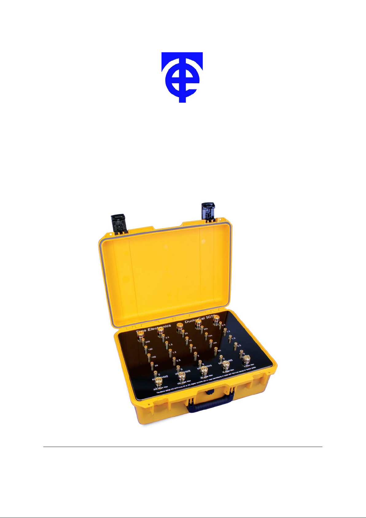
Time Electronics
5070 DuctorCal
Ductor Tester and Micro-Ohmmeter Calibrator
Technical Manual
V5.1 19/03/12 Time Electronics Ltd
Botany Industrial Estate, Tonbridge, Kent, TN9 1RH
Tel: +44(0)1732 355993 Fax: +44(0)1732 770312
Email: mail@TimeElectronics.co.uk
Web Site: www.TimeElectronic s .com
Page 2

2
2
Contents
1. General Description ........................................................................................... 3
2. Specifications ..................................................................................................... 4
2.1. Technical Specification ...................................................................................... 4
2.2. General Specification ......................................................................................... 4
3. Operation ............................................................................................................ 5
3.1. Example Connection .......................................................................................... 6
3.2. Operating Precautions ....................................................................................... 6
4. Guarantee & Servicing ....................................................................................... 7
All Time Electronics' instruments are subjec t to continuous development and improvem ent and in consequence
may incorporate minor detail changes from the information contained herein.
5070 Technical Manual
Page 3
3
1. General Description
3
The 5070 is a portable instrument suitable for calibrating high current Ductor Testers and
Micro-Ohm meters. It contains 5 sets of high current rating standard resistors which simulate
the resistance being measured.
It has full 4 terminal capabilities with extra large terminals for the current connection.
Gold plated terminals are used throughout to reduce contact resistance and thermal
emfs (for dc based instruments).
It has a substantial maximum continuous current rating but is also suitable for much
higher transient/pulse test currents.
The internal resistance standards are all high quality manganin types with good long
term stability and temperature coefficients.
5070 Technical Manual
Page 4

4
2. Specifications
2.1. Technical Specification
4
Range
50, 100, 150, 200µΩ 200A 0.8%
0.5, 1, 1.5, 2mΩ 100A 0.5%
5, 10, 15, 20mΩ 30A 0.2%
50, 100, 150, 200mΩ 10A 0.1%
0.5, 1, 1.5, 2Ω 3A 0.1%
The currents shown are the continuous rated currents for both AC and DC.
Higher currents can be used intermittently as supplied by pulse driven instruments. With an
ON to OFF time ratio of 1:10 or less, the allowed peak currents ar e 10x those specified
above, with an upper limit of 1000A and with a maxim um applied tim e of 4 seconds. At least
1 minute should be allowed between applications for cooling.
It is important to ensure there is adequate low resistance connections on t he 5070’s
current terminals.
Current
Accuracy
2.2. General Specification
Dimensions: W540 x H210 x D410mm
Weight: 11kg
5070 Technical Manual
Page 5

5
5
Current Terminals
Current
Current -
Voltage
Voltage
3. Operation
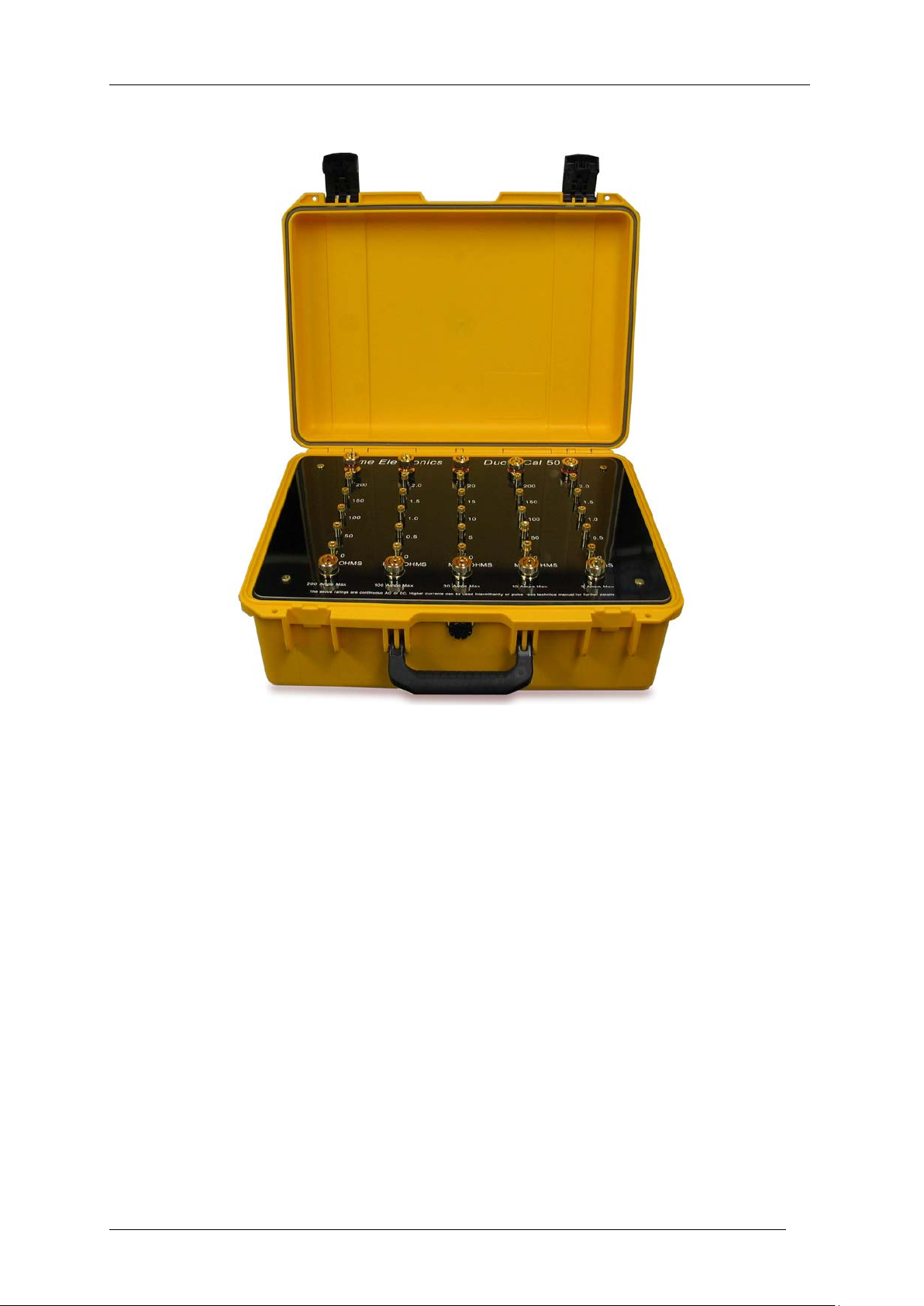
The front panel contains 5 rows of high quality gold plated terminals. All are suitable for
4mm plug insertion on screw compression connectors.
For current connection, large 25mm diameter terminals are provided. The outer ring can be
completely removed for clamp connections.
It is important that the correct good quality spade terminations are used for currents above
50A since arking can cause damage to the terminals.
Connections to the voltage terminals is less critical, but to minimize errors to the thermal emf
generation it is recommended that gold plated 4mm plugs are used.
Care should be taken to ensure that only the voltage terminals are used for the voltage
measurement.
Voltage
Terminals
DUCTOR
TESTER
-
5070 Technical Manual
Page 6

6
6
3.1. Example Connection
In the example below a T & R DSM200 is connect ed for calibration of the 200A range.
3.2. Operating Precautions
If thermal emfs are suspected the voltage terminal output should be checked on all positions
with zero current flowing (current leads disconnected).
The zero position is checked with the voltage potential leads from the unit being c alibrated,
connected together on the 5070’s ‘0’ voltage terminal.
5070 Technical Manual
Page 7

7
7
Disposal of your old equi pment
4. Guarantee & Servicing
Guarantee Period
This unit is guaranteed against defects in materials and workmanship for a period of one
year from its delivery to the customer.
We maintain comprehensive after sales facilities and the unit can, if necessary be returned
to us for servicing. During this period, Time Electronics Ltd will, at its discretion, repair or
replace the defective items. For servicing under guarantee, the instrument type and serial
number must always be quoted, together with details of any fault and the ser vice required.
The purchaser of the instrument must prepay all shipping charges. Time Electronics Ltd will
pay return shipping charges.
This guarantee is void if servicing has been attempted by an unauthorised person or agent.
If, during the guarantee period, failure is due to m isuse or abuse of the unit, the repair will be
put in hand without delay and charged unless other instructions are received.
Please note that if you require a new UKAS Certificate during the war ranty period, this will
be charged at the current rate on our price list.
Service After Guarantee Period
Even after the guarantee period has expired, Time Electronics Ltd., can still service your
instrument. As the manufacturer, we have the specialised knowledge needed to keep your
instrument in peak condition and we also maintain a comprehensive spare parts service.
Please enclose details of the service required and your full company details including a
contact name when returning for servicing.
Returning Instruments
When returning instruments, please ensure that they have been adequately packed,
preferably in the original packing supplied. Time Electronics Ltd will not accept
responsibility for units returned damaged. Please ensure that all units have details of the
service required and all relevant paperwork.
Send the instrument, shipping charges paid to:-
Time Electronics Ltd
Botany Industrial Estat e, Tonbr i dg e, K ent, TN9 1RH
Tel: +44(0)1732 355993 Fax: +44(0)1732 770312
Email: mail@TimeElectronics.co.uk
Web Site: www.TimeElectronics.c om
5070 Technical Manual
1. When this crossed-out wheeled bin symbol is attached to a product it means the
product is covered by the European Directive 2002/96/EC.
2. All electrical and electronic products should be disposed of separately from the
municipal waste stream via designated collection facilities appointed by the
government or the local authorities.
3. The correct disposal of your old appliance will help prevent potential negative
consequences for the environment and human health.
4. For more detailed information about disposal of your old appliance, please contact
your city office, waste disposal service or return to Time Electronics.
 Loading...