

Page 1
Time Electronics
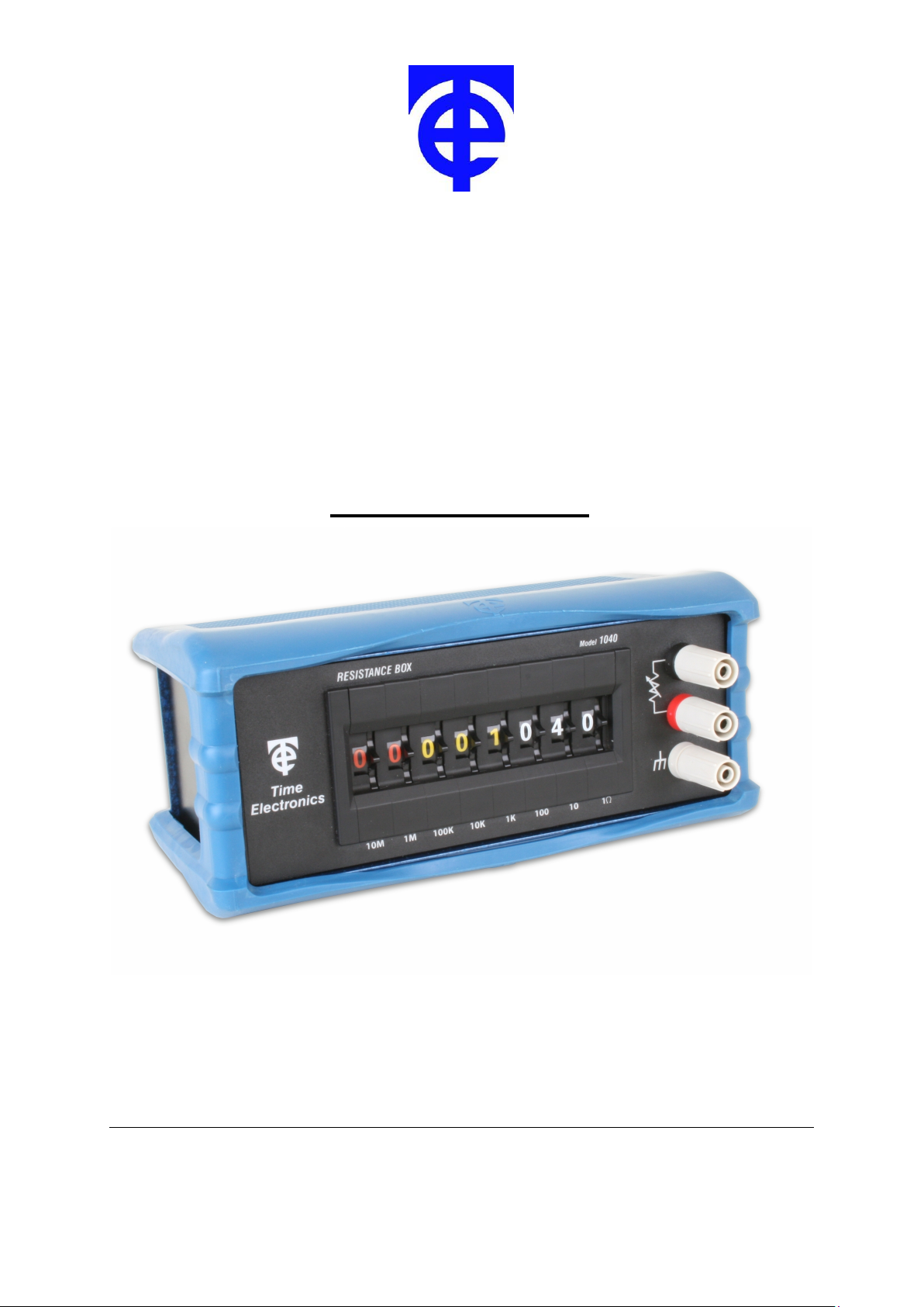
1040
Decade Resistance Box
Technical Manual
V1.5 25/06/13 Time Electronics Ltd
Botany Industrial Estate, Tonbridge, Kent, TN9 1RH
Tel: +44(0)1732 355993 Fax: +44(0)1732 770312
Email: mail@TimeElectronics.co.uk
Web Site: www.TimeElectronics.com
Page 2

1
1
Contents
1. Specifications ................................................................................................... 2
2. Operation of the 1040 ...................................................................................... 3
3. Controls ............................................................................................................ 4
4. Maintenance and Repair .................................................................................. 5
5. Guarantee & Servicing ..................................................................................... 6
Manuel Technique (Francais) ................................................................................. 7
Technisches Handbuch (Deutsch) ....................................................................... 11
Manual Técnico (Italiano) ..................................................................................... 15
All Time Electronics' instruments are subject to continuous development and
improvement and in consequence may incorporate minor detail changes from the
information contained herein.
1040 Technical Manual
Page 3
2
1. Specifications
Resistance Range: 1
2
Ω to 100MΩ in 1Ω steps
RANGE
SPEC.
MAX
CURRENT
Zero Residual Resistance: less than 250 m
Power Rating: 1 watt per resistor. Metal film resistors are used through out.
Maximum Working Voltage: 250 volts DC/AC RMS.
Maximum Current : 0.5 amp DC, 0.36 amp AC (RMS).
Temperature Coefficient: 50 ppm per ºC
Connections: 4 mm terminals. A third terminal is to enable the case to be
Construction: The case is of robust metal construction finished in two-tone
Dimensions:
(215 x 100 x 120mm including protective boot).
Weight: 0.6 kg (1.0 kg incl. protective boot)
Optional Extras: A carrying case is available for field and industrial applications.
1Ω 10Ω 100Ω 1kΩ 10kΩ 100kΩ 1MΩ 10MΩ
± 1% ± 0.5% ± 0.1% ± 0.1% ± 0.1% ± 0.1% ± 0.1% ± 1%
0.5A 0.3A 100mA 30mA 3mA 0.3mA 0.03mA 3µA
Ω
earthed or connected to either output.
blue and black.
W200 x H75 x D110mm
Code
1040
9026
9161
9114
Description
Wide Range Resistance Box
Leatherette Carry Case
Factory (NPL Traceable) Calibration Certificate
UKAS Calibration Certificate (ISO 17025)
1040 Technical Manual
Page 4

3
3
2. Operation of the 1040
The 1040 is a compact, robust and accurate decade resistance box designed to meet the
needs of both industry and education. Housed in a robust metal case, the compact
construction makes it easily portable.
Metal film resistors are used to obtain the high stability and low temperature co-efficient.
It is imperative that the switch setting should be unambiguous in order to avoid misreading
the set value. To prevent misreading, the 1040 incorporates a unique colour coding system
to divide the setting into 3 groups corresponding to ohms, kilohms and megohms.
Resistance is simulated by dialling the value required using the thumbwheel switches. This
enables precise setting with a clear unambiguous indication. For example—to simulate
3k83 set the 1k bank to 3, the 100Ω bank to 8 and the 10Ω bank to 3, all the other dials set
to zero.
Connection to the box is via 4mm terminal posts, 4mm plugs or stripped wire connections
can be used.
The red and black terminals connect to the resistance and the grey terminal is connected to
the case for screening purposes.
Special attention has been given to the problem of reliability of operation. A special multiple
gold contact switch arrangement ensures that a back-up contact is always available to take
over should a failure occur.
Note : Remember that all resistance boxes have a residual resistance, i.e. when the dials
are set to zero a small resistance remains. If you are making precision measurements or
recalibrating the instrument, this residual value must be subtracted from all measurements.
1040 Technical Manual
Page 5
4
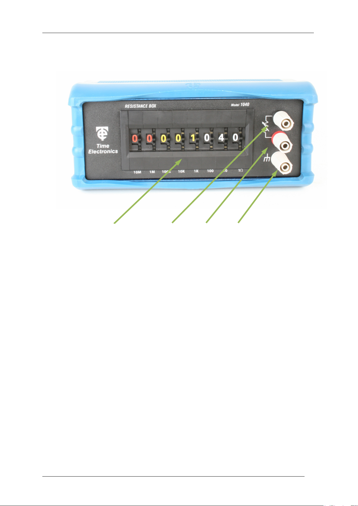
3. Controls
1 2 3 4
4
1) 8 way Decade Bank Selects Output value of resistance.
2) Black 4mm terminals Resistance output terminal.
3) Red 4mm terminals Resistance output terminal.
4) Grey 4mmTerminal A third terminal is to enable the case to
be earthed or connected to either output.
1040 Technical Manual
Page 6

5
5
4. Maintenance and Repair
Dismantling the Instrument
Remove rubber protection boot and then removal of four screws enables the cover to be
taken off which provides access to all parts of the instrument.
Repair
NOTE: No repair work should be undertaken by the customer while the instrument is
under warranty as such work may render the warranty invalid.
Certain of the precision components used in this instrument are not readily available and
make repairs by the customer difficult if these components are damaged.
Overload conditions can cause a unit failure.
1040 Technical Manual
Page 7

6
6
Disposal of your old equipment
5. Guarantee & Servicing
Guarantee Period
This unit is guaranteed against defects in materials and workmanship for a period of one
year from its delivery to the customer.
We maintain comprehensive after sales facilities and the unit can, if necessary be returned
to us for servicing. During this period, Time Electronics Ltd will, at its discretion, repair or
replace the defective items. For servicing under guarantee, the instrument type and serial
number must always be quoted, together with details of any fault and the service required.
The purchaser of the instrument must prepay all shipping charges. Time Electronics Ltd will
pay return shipping charges.
This guarantee is void if servicing has been attempted by an unauthorised person or agent.
If, during the guarantee period, failure is due to misuse or abuse of the unit, the repair will be
put in hand without delay and charged unless other instructions are received.
Please note that if you require a new UKAS Certificate during the warranty period, this will
be charged at the current rate on our price list.
Service After Guarantee Period
Even after the guarantee period has expired, Time Electronics Ltd., can still service your
instrument. As the manufacturer, we have the specialised knowledge needed to keep your
instrument in peak condition and we also maintain a comprehensive spare parts service.
Please enclose details of the service required and your full company details including a
contact name when returning for servicing.
Returning Instruments
When returning instruments, please ensure that they have been adequately packed,
preferably in the original packing supplied. Time Electronics Ltd will not accept
responsibility for units returned damaged. Please ensure that all units have details of the
service required and all relevant paperwork.
Send the instrument, shipping charges paid to:-
Time Electronics Ltd
Botany Industrial Estate, Tonbridge, Kent, TN9 1RH
Tel: +44(0)1732 355993 Fax: +44(0)1732 770312
Email: mail@TimeElectronics.co.uk
Web Site:
www.TimeElectronics.com
1040 Technical Manual
1. When this crossed-out wheeled bin symbol is attached to a product it means the
product is covered by the European Directive 2002/96/EC.
2. All electrical and electronic products should be disposed of separately from the
municipal waste stream via designated collection facilities appointed by the
government or the local authorities.
3. The correct disposal of your old appliance will help prevent potential negative
consequences for the environment and human health.
4. For more detailed information about disposal of your old appliance, please contact
your city office, waste disposal service or return to Time Electronics.
Page 8

7
7
Time Electronics
BOÎTE DE RÉSISTANCES À DÉCADES
1040
Manuel Technique (Francais)
Time Electronics Ltd
Botany Industrial Estate, Tonbridge, Kent, TN9 1RH
Tel: +44(0)1732 355993 Fax: +44(0)1732 770312
E-Mail: mail@TimeElectronics.co.uk
Web Site: www.timeelectronics.com
1040 Technical Manual
Page 9

8
8
CARACTÉRISTIQUES TECHNIQUES
Plage de résistance : 1 Ω à 100 MΩ par pas de 1 Ω
RANGE
SPEC.
1Ω 10Ω 100Ω 1kΩ 10kΩ 100kΩ 1MΩ 10MΩ
± 1% ± 0.5% ± 0.1% ± 0.1% ± 0.1% ± 0.1% ± 0.1% ± 1%
MAX
0.5A 0.3A 100mA 30mA 3mA 0.3mA 0.03mA 3µA
COURENT
Résistance résiduelle à zéro : Inférieure à 250 mΩ
Service nominal continu maximal : 1 watt par résistance. Des résistances à
film métallique sont utilisées partout.
o
Coefficient de température : 50 ppm par
C
Connexions : Bornes de 4 mm. Une quatrième borne
est prévue pour activer le boîtier à relier
à la terre ou à connecter à l’une ou l’autre des sorties.
Construction : Le boîtier est de construction métallique
robuste fini en deux tons, bleu et noir.
Dimensions : 110 x 75 x 200 mm
Poids : 0,6 kg
Suppléments en option : Une malette de transport est disponible
pour les applications industrielles et sur
le terrain.
1040 Technical Manual
Page 10

9
9
FONCTIONNEMENT
Le 1040 est une boîte de résistances en décades robuste et précise conçue pour répondre
aux besoins à la fois de l’industrie et de l’enseignement. Logée dans un boîtier métallique
robuste, la construction compacte la rend facilement portable.
Des résisteurs à film métallique sont utilisés pour obtenir le coefficient de haute stabilité et
de basse température.
Il est impératif que le positionnement des commutateurs ne soit pas ambigu pour éviter de
mal lire la valeur réglée. Pour éviter une interprétation erronée, le 1040 est doté d’un
système de codage par couleurs afin de diviser le réglage en 3 groupes correspondant aux
ohms, kilohms et mégohms.
La résistance est simulée en composant la valeur requise à l’aide des interrupteurs à
molette. Ceci permet un réglage précis avec une indication claire, exempte d’ambiguïté. À
titre d’exemple – pour simuler une valeur de 3 k83, réglez le cadran de 1k sur 3, le cadran
de 100 Ω sur 8 et le cadran de 10 Ω sur 3, tous les autres cadrans doivent être réglés sur
zéro.
Le branchement à la boîte se fait par l’intermédiaire de fiches bananes. Deux connexions
rouge et noir sont raccordées à la résistance et la borne verte est raccordée au boîtier pour
des objectifs de dépistage.
Une attention particulière a été accordée au problème de la fiabilité du fonctionnement. Un
arrangement spécial de commutateurs à contacts en or multiples garantit qu’un contact de
réserve est toujours disponible pour prendre la relève en cas de panne.
Remarque : Gardez à l’esprit que toutes les boîtes de résistance à fiches ont une résistance
résiduelle. À savoir que si les cadrans sont réglés sur zéro, une petite résistance subsiste.
Si vous faites des mesures de précision ou que vous recalibrez l’instrument, cette valeur
résiduelle doit être soustraite de toutes les mesures.
1040 Technical Manual
Page 11

10
10
GARANTIE ET ENTRETIEN
PÉRIODE DE GARANTIE
Cette unité est garantie contre les défauts et les malfaçons pendant une période d’un an à
partir de la date de sa livraison au client.
Nous offrons des facilités d’après-vente complètes et l’unité, peut, si nécessaire, nous être
renvoyée pour un entretien. Durant cette période, Time Electronics Ltd, réparera ou
remplacera, à sa libre appréciation, l’élément défectueux. Pour un entretien couvert par la
garantie, vous devrez toujours citer le type de l’instrument et le numéro de série ainsi que
mentionner les détails de tout défaut éventuel et de l’intervention d’entretien requise.
L’acheteur de l’instrument doit payer d’avance tous les frais d’expédition. Time Electronics
Ltd prendra en charge les frais de livraison de retour.
Cette garantie est nulle et non avenue si une intervention d’entretien a été tentée par une
personne ou un agent non autorisé(e). Si durant la période de garantie, un défaut est dû à
un mauvais emploi ou à un abus de l’unité, la réparation sera effectuée immédiatement et
elle sera, sauf instructions contraires, tarifée au client.
ENTRETIEN APRÈS LA PÉRIODE DE GARANTIE
Time Electronics Ltd peut réviser votre instrument même après que la période de garantie a
expiré. À titre de fabriquant, nous avons les connaissances spécialisées nécessaires pour
garder votre instrument en excellente condition et nous offrons également un service de
pièces de rechange complet.
Lorsque vous renvoyez l’instrument pour un entretien, veuillez donner les détails du service
dont vous avez besoin et les détails complets de votre société, y compris le nom figurant sur
le contrat.
RENVOI D’ INSTRUMENTS
Lorsque vous renvoyez des instruments, veuillez vous assurer qu’ils ont été adéquatement
emballés, de préférence dans l’emballage d’origine fourni. La société Time Electronics Ltd.
n’acceptera pas d’être tenue pour responsable des unités endommagées. Veuillez vous
assurer que toutes les unités sont accompagnées de tous les détails de l’intervention
d’entretien nécessaire et de toutes les écritures pertinentes.
Envoyez l’instrument, frais de livraison prépayés à :
Time Electronics Ltd
Botany Industrial Estate, Tonbridge, Kent, TN9 1RH
Tel: +44(0)1732 355993 Fax: +44(0)1732 770312
E-Mail: mail@TimeElectronics.co.uk
Web Site: www.timeelectronics.com
1040 Technical Manual
Page 12

11
11
Time Electronics
1040 WIDERSTANDSDEKADE
Technisches Handbuch (Deutsch)
Time Electronics Ltd
Botany Industrial Estate, Tonbridge, Kent, TN9 1RH
Tel: +44(0)1732 355993 Fax: +44(0)1732 770312
E-Mail: mail@TimeElectronics.co.uk
Web Site: www.timeelectronics.com
1040 Technical Manual
Page 13

12
12
SPEZIFIKATION
Widerstansbereich: 1 Ohm bis 100 Mohm in 1 Ohm Schritten
Dekade
Genauigkeit
max. Strom
Nullrestwiderstand: als 250 mOhm
Last: 1W pro Widerstand durchgehend Metallwid-erstände
Temperaturkoeffizient: 50 ppm pro ºC
Verbindungen: 4 mm Buchsen, ein dritter Kontakt ist zum Erden
1Ω 10Ω 100Ω 1kΩ 10kΩ 100kΩ 1MΩ 10MΩ
± 1% ± 0.5% ± 0.1% ± 0.1% ± 0.1% ± 0.1% ± 0.1% ± 1%
0.5A 0.3A 100mA 30mA 3mA 0.3mA 0.03mA 3µA
des Gehäuses oder kann mit einer der
anderen Buchsen verbun den werden.
Konstruktion: Das Gehäuse ist eine robuste Metallkonstruk-tion,
zweifarbig—blau und schwarz
Dimensionen: 110 x 75 x 200 mm
Gewicht: 0.6 Kg
Optionale Extras: Tragetasche für Feldund Industrieeinsat
1040 Technical Manual
Page 14

13
13
EINFUHRUNG
Die 1040 ist eine kompakte, robuste und genaue Widerstandsdekade, die sowohl den
Industrieals auch den Ausbildungsbedarf abdeckt. Sie ist in einem robustenMetallgehäuse
untergebracht und die kompakte Konstruktion macht sie leicht tragbar. Bei Gebrauch im
Labor nimmt sie minimalen Raum ein.
Die hohe Genauigkeit wird durch Metallfilmwiderstände erreicht. Die Genauigkeit bei kleinen
Widerständen wird durch den Schalterkontakt bestimmt, der auf einem Minimum gehalten
wird. Im mittleren Bereich ist die Genauigkeit 0.1% und besser. Die Drehschalter erlauben
eine präzise Einstellung des Ausgangswiderstandes mit unzweideutiger Anzeige.
Es werden Metallfilmwiderstände benutzt, um die hohe Stabilität und den kleinen
Temperaturkoeffizienten zu erreichen. Der Temperaturkoeffizientist typisch besser als 50
ppm pro ºC. Jeder Widerstand ist für 1 Watt Last ausgelegt.
Es ist notwendig, die Schalter unzweifelhaft zu setzen, damit keine Fehlablesung möglich
ist. Die Möglichkeit einer Fehlablesung steigt mit der Zahl der Ziffern erheblich. Um eine
Fehlablesung zu vermeiden, enthält die 8000 ein Farbcodiersystem, um die Einstellung in 3
Gruppenkorrespondierend mit ohm, Kohm und Mohm. Dieses Feature macht die 1040 ideal
für den Ausbildungseinsatz.
Besondere Aufmerksamkeit wurde auf das Problem der Zuverlässigkeit gelegt.Ein spezieller
Vielfachgoldkontakt sorgt für einen Back-Up-Kontakt im Falle eines Fehlkontaktes.
Bemerke: Beachten Sie daß alle Widerstandsboxen einen Nullrestwiderstand haben, wenn
alle Banken auf Null gesctzt sind. Bei exakten Messungen oder bei der Rekalibrierung des
Instrumentes, muss dieser Restwiderstand vonallen Messungen abgezogen werden.
1040 Technical Manual
Page 15

14
14
GARANTIE UND SERVICE
GARANTIEPERIODE
Dieses Gerät unterliegt einer Garantie gegen Defekte im Material und Fertigung für ein Jahr
ab Lieferung zum Kunden.
Wir unterhalten umfangreiche “After-Sales-Abteilungen” und das Gerät kann jederzeit zum
Service eingeschickt werden. Während dieser Periode wird TE diese Einheit reparieren und
defekte Teile kostenlos ersetzen Zum Service unter Garantie geben Sie bitte Instrumenten
type, die Ser-Nr und eine detaillierte Fehlerbeschreibung sowie den benötigten Service an.
Der Käufer wird gebeten die Frachtkosten beim Transport zu TE zu bezahlen. TE
übernimmt die Frachtkosten der Rücksendung.
Die Garantie geht verloren, wenn das Gerät durch eine nicht authorisierte Person oder vom
Agenten repariert wurde. Falls während der Garantieperiode ein Fehler durch
unsachgemäße Behandlung des Gerätes auftritt, dann wird das Gerät automatisch gegen
Kostenerstattung repariert, es sei denn, daß vorher andere Vereinbarungen getroffen
wurden.
SERVICE NACH DER GARANTIEPERIODE
Auch nach der Garantieperiode übernimmt TE den Service für das Instrument. Als
Hersteller haben wir das entsprechende Know-How, Ihr Gerät in Topkonditionen zu
erhalten, und wir besitzen ein umfangreiches Ersatzteillager.
Bitte fügen Sie eine detaillierte Fehlerbeschreibung und den gewünschten Service schriftlich
bei und nennen Sie uns eine Kontaktperson.
RÜCKSENDUNG VON INSTRUMENTEN
Wenn Sie Geräte zurücksenden, achten Sie auf eine adäqute Verpackung, bevorzugt in der
Originalverpackung. TE übernimmt keine Verantwortung für Transportschäden. Stellen Sie
bitte sicher, daß alle Servicedetails und Unterlagen der Sendung beigefügt sind.
Senden Sie das Gerät, Transportkosten bezahlt, an :
Time Electronics Ltd
Botany Industrial Estate, Tonbridge, Kent, TN9 1RH
Tel: +44(0)1732 355993 Fax: +44(0)1732 770312
E-Mail: mail@TimeElectronics.co.uk
Web Site: www.timeelectronics.com
1040 Technical Manual
Page 16

15
15
Time Electronics
CASSETTA DI RESISTENZA A DECADI
1040
Manual Técnico (Italiano)
Time Electronics Ltd
Botany Industrial Estate, Tonbridge, Kent, TN9 1RH
Tel: +44(0)1732 355993 Fax: +44(0)1732 770312
E-Mail: mail@TimeElectronics.co.uk
Web Site: www.timeelectronics.com
1040 Technical Manual
Page 17

16
16
SPECIFICHE
Campo di resistenza: da 1Ω a 100MΩ a passi di 1Ω
Decade
Precisione
Corrente
max
1Ω 10Ω 100Ω 1kΩ 10kΩ 100kΩ 1MΩ 10MΩ
± 1% ± 0.5% ± 0.1% ± 0.1% ± 0.1% ± 0.1% ± 0.1% ± 1%
0.5A 0.3A 100mA 30mA 3mA 0.3mA 0.03mA 3µA
Resistenza residua a zero: inferiore a 250mΩ.
Potenza: 1 watt per resistore. Vengono utilizzate
solamente resistenze a pellicola metal lica.
Coefficiente di temperatura: 50 ppm per °C
Connessioni: Terminali (4mm). Un terzo terminale
consentirà il collegamento a terra della
cassetta o il collegamento a una delle due
uscite.
Costruzione: La cassetta è in metallo robusto conrifiniture
a due tonalità di colore, in blue nero.
Dimensioni: 110mm x 75mm x 200 mm
Peso: 600 g.
Accessori optional: Custodia da trasporto per applicazioni
industriali e impieghi di lavoro all’aperto.
1040 Technical Manual
Page 18

17
17
FUNZIONAMENTO
La cassetta di resistenza a decadi 1040 è compatta, robusta e precisa ed è stata progettata
per soddisfare le esigenze di coloro che operano sia nell’industria che nel campo didattico.
Contenuta in una cassetta metallica, la costruzione compatta di questa cassetta la rende
facilmente trasportabile.
Le resistenze a pellicola metallica vengono utilizzate per ottenere il coefficiente di bassa
temperatura ed alta stabilità.
È essenziale che il meccanismo di regolazione sia chiaro e non equivoco per evitare la
lettura errata del valore impostato. A tale scopo, la cassetta di resistenza 1040 incorpora un
particolare sistema di codifica a colori per dividere il quadrante di lettura in tre gruppi diversi
corrispondenti a ohm, kilohm e megohm.
La simulazione della resistenza avviene tramite impostazione mediante commutatore sul
valore desiderato. Ciò consente un’impostazione accurata con conseguente indicazione
chiara e non ambigua. Ad esempio, per simulare 3k83 è necessario impostare il quadrante
1k su 3, il quadrante 100Ω su 8 e il quadrante 10Ω su 3, lasciando tutti gli altri quadranti
impostati sullo zero.
La connessione alla cassetta avviene tramite spine banana di 4mm. La connessione rossa
e quella nera sono collegate alla resistenza, mentre il terminale verde è collegato alla
cassetta a scopo di controllo.
Si è prestata un’attenzione particolare al problema dell’affidabilità del funzionamento. A tale
scopo, un dispositivo speciale di interruttori multipli a contatto d’oro garantisce che vi sia
sempre un contatto di riserva in caso di guasto.
Nota: Tutte le cassette di resistenza hanno una resistenza residua, ossia anche quando i
quadranti sono impostati sullo zero, resta sempre una resistenza minima. Nell’effettuare una
misurazione accurata o la taratura dello strumento, bisognerà sempre sottrarre questo
valore residuo da tutte le misure.
1040 Technical Manual
Page 19

18
18
GARANZIA E ASSISTENZA TECNICA
PERIODO DI GARANZIA
Questa unità è garantita contro difetti del materiale e di lavorazione per un periodo di un anno dalla
data consegna al cliente.
Se necessario, l’unità può essere riconsegnata per usufruire dell’ efficiente servizio di riparazione e
assistenza tecnica post-vendita in loco. Durante tale periodo di garanzia, Time Electronics Ltd. userà
il proprio giudizio discrezionale per decidere se riparare o sostituire l’articolo difettoso. Per usufruire
del servizio di riparazione sotto garanzia, è necessario citare sempre il tipo di strumento e il numero
di serie ad esso associato, come pure sottomettere una descrizione dettagliata del difetto di
funzionamento e del tipo di servizio richiesto. Tutte le spese di spedizione sono a carico
dell’acquirente dell’articolo e devono essere pagate anticipatamente. Tuttavia, a riparazione
avvenuta, Time Electronics Ltd. Si assumerà le spese di spedizione dell’articolol
Questa garanzia è nulla se l’articolo in questione è stato sottoposto a previo servizio di riparazione
effettuato da persone o rappresentanti non autorizzati. Nel caso in cui l’articolo sotto garanzia sia
aottoposto ad abuse o uso errato che ne determini il cattivo o mancato funzionamento, verrà messo a
disposizione un immediato servizio di riparazione a pagamento, a meno che il cliente non desideri
altrimenti.
ASSISTENZA TECNICA POST-GARANZIA
Al termine del periodo di validità della garanzia, Time Electronics Ltd. Sarà pur sempre in grado di
offrire un eccellente servizio di assistenza tecnica. Come casa produttrice, disponiamo della
conoscenza specialistica necessaria a mantenere il vostro strumento in condizioni di funzionamento
perfette. Siamo inoltre in grado di offrire alla nostra clientela una vasta gamma di pezzi di ricambio
ed altri accessori.
Nel caso in cui abbiate bisogno di inviare un articolo per riparazioni, siete pregati di includere il ripo di
servizio richiesto, tutti I particolari relativi alla vostra azienda e la persona da contattare a riparazione
avvenuta.
SPEDIZIONE DEGLISTRUMENTI
Quando spedite gli strumenti per servizi di riparazione o di assistenza tecnica, siete pregati di
prestare la dovuta attensione alle operazioni di imballaggio oer evitare di danneggiare gli articoli
durante il trasporto. A tale scopo, sarebbe opportuno ultilizzare I contenitori o le scatole originali di
fabbricazione. Time Electronics Ltd. Non si assumerà alcuna responsabilità per I danni subiti dalle
unità restituite a scopo di reparazione. Siete inoltre pregati di controllare che tutte le unità siano
accompagnate da una chiara descrizione del servizio richiesto, come pute dalla relativa
documentazione.
Siete pregati di inviare o strumento con tutte le spese di spedizione pagate anticipatamente a :
Time Electronics Ltd
Botany Industrial Estate, Tonbridge, Kent, TN9 1RH
Tel: +44(0)1732 355993 Fax: +44(0)1732 770312
E-Mail: mail@TimeElectronics.co.uk
Web Site: www.timeelectronics.com
1040 Technical Manual
 Loading...