

Page 1
Time Electronics
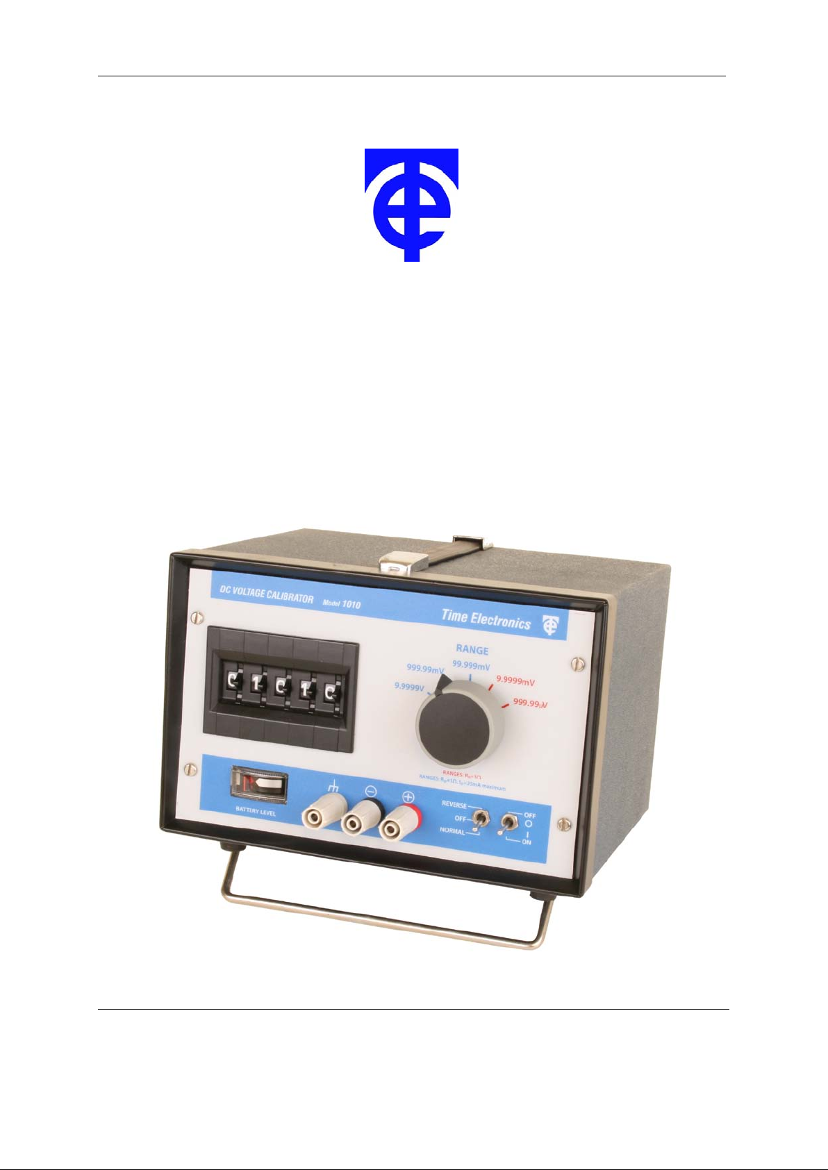
1010 DC Voltage Calibrator
Technical Manual
V1.1 20/04/09 Time Electronics Ltd
Botany Industrial Estate, Tonbridge, Kent, TN9 1RH
Tel: +44(0)1732 355993 Fax: +44(0)1732 770312
Email: mail@TimeElectronics.co.uk
Web Site: www.TimeElectronic s .com
Page 2

2
C ontents
1. Introduction ............................................................................................................ 3
1.1. General Description ................................................................................................ 3
1.2. Specifications ......................................................................................................... 3
1.3. Power Unit ............................................................................................................... 4
1.4. Circuit Description .................................................................................................. 4
1.5. Applications ............................................................................................................ 4
2. Operation ................................................................................................................ 5
2.1. Operating Procedure .............................................................................................. 5
2.1.1. Operating Position ........................................................................................................ 5
2.1.2. Output terminals ........................................................................................................... 5
2.1.3. Case terminal ............................................................................................................... 5
2.2. Front Panel Controls .............................................................................................. 5
2.2.1. Supply on/off ................................................................................................................. 5
2.2.2. Output polarity .............................................................................................................. 5
2.2.3. Battery level .................................................................................................................. 5
2.2.4. Output voltage range .................................................................................................... 5
2.2.5. Output level: ................................................................................................................. 5
2.3. Output noise ........................................................................................................... 6
2.4. Common mode noise ............................................................................................. 6
2.5. Thermal emfs .......................................................................................................... 6
2.6. Fuses ....................................................................................................................... 6
2.7. Mains Power Unit .................................................................................................... 7
2.7.1. Type PU2 ...................................................................................................................... 7
2.7.2. Constructional details PU2 ........................................................................................... 7
2.7.3. 240V to 110V conversion ............................................................................................. 7
3. Constructional Layout Details .............................................................................. 8
3.1. Chopper amplifier module ..................................................................................... 8
3.1.1. Description .................................................................................................................... 8
3.1.2. Module replacement ..................................................................................................... 8
4. Recalibration .......................................................................................................... 9
4.1. Zero ......................................................................................................................... 9
4.2. Full Scale ................................................................................................................. 9
4.3. Calibration Procedure ...........................................................................................11
4.4. 10mV and 1mV Range Calibration ........................................................................11
5. Guarantee & Servicing ......................................................................................... 12
All Time Electronics' instruments are subject to continuous development and improvement and in consequence
may incorporate minor detail changes from the information contained herein.
1010 Technical Manual
2
Page 3

3
1. Introduction
1.1. General Description
The 1010 is an accurate battery/mains powered voltage calibrator sourcing up to 10 volts in
5 ranges with a resolution up to 0.01uV.
A precision zener reference diode is used as a basic reference source and low temperature
coefficient resistors are used. Power is provided by a mains/rechargeable battery power
unit. A front panel indicator monitors the battery condition. The completely solid state circuit
design provides automatic standardisation against the internal reference and allows up to
30mA output current with less than 0.1 ohms output resistance. Short circuit overload
protection and a normal-off-reverse switch are provided.
1.2. Specifications
Ranges: 0-9.9999V in 5 ranges
0-9.9999V in 100uV steps
0-999.99mV in 10uV steps
0-99.999mV in 1uV steps
0-9.9999mV in 0.1uV steps
0-999.99uV in 0.01uV steps
Accuracy: 10V & 1V ranges: ± 0.02% of setting + ± 0.005% of range
100mV range: ± 0.05% of setting + ± 0.005% of range, ± 1uV
10mV & 1mV Ranges: ± 0.05% of setting + ± 0.005% of range, ± 4uV
Setting Resolution: 5 digits
Output Resistance: Less than 0.1 ohm (type 0.05 ohm) on 10V, 1V and 0.1V ranges.
1 ohm on lower ranges.
Maximum Output 25mA max. on 10V, 1V & 0.1V ranges (an internal short circuit current
Current: limit is set at approx 30mA). Lower ranges can be loaded up to the
short circuit current value although it should be noted that loads less
than 1000 ohms will give greater than 0.1% error.
Maximum Overload: The instrument can withstand a continuous short circuit on the output.
Output Voltage Less than 30 ppm/°C to +50°C)
Stability: Less than 20 ppm/V variation in supply voltage.
Less than 75 ppm/year not cumulative.
Less than 10 ppm/hr at constant temperature.
Output Polarity: Positive or negative switch selected. A centre ‘off’ position on this
switch provides a short circuit on the output for 1010 voltage source.
Output Noise Level: 10, 1 & 0.1V ranges, less than 10 ppm of setting +/- 2uV (0-10 Hz).
10mV & 1mV ranges, less than +/- 0.05uV (0-10 Hz)
Dimensions: 20 x 160 x 190 mm.
Weight: Approximately 3.3kg.
1010 Technical Manual
3
Page 4

4
1.3. Power Unit
The 1010 is supplied with a mains/battery power unit. This can be configured when ordered
for either 115V or 230V AC, 50/60Hz. See section 2.7.3.
1.4. Circuit Description
The calibrator employs a temperature compensated zener diode as the basic reference
source. This provides the input to a FET chopper amplifier system which operates in a feedback stabilised mode, and has a gain value determined by a set of precision metal film
resistors which are selected by a 5 decade thumbwheel switch. The output voltage is
variable from 0 to 9.9999 volts in 5 ranges. An output resistance of typically 0.05 ohms is
maintained on the top three ranges; the maximum output current that can be drawn on
these ranges is automatically limited to 30mA. This is to prevent damage to the circuitry in
the event of accidental short circuit etc.
The lower ranges have an output resistance of 1 ohm and will supply current up to the short
circuit value. To ensure complete reliability the range switch employs two contacts in parallel
for each position - even if a contact fails the 1010 still functions correctly.
1.5. Applications
The uses of the instrument include the calibration applications of conventional voltage
potentiometers. A 1010 in these applications has the advantage of requiring no
standardisation and being able to supply much higher output currents without loss of
accuracy. Long term stability is inherent since standardisation is not required.
Other applications as a precision voltage source include calibration, linearity and gain
stability measurements, etc., on D.C. amplifiers, digital and electronic voltmeters,
transducers and as a variable low current power supply or backing-off voltage. The 10
ppm/HR stability and low noise levels are of particular interest when an extremely stable
voltage is required rather than a high accuracy calibration source.
1010 Technical Manual
4
Page 5

5
2. Operation
2.1. Operating Procedure
Operation of the 1010 is self explanatory from the front panel controls and specification.
Normal precautions concerning overload and incorrect range etc., should be observed.
Battery condition should be checked on the front panel display before and during use.
For quick zeroing of output set the Polarity switch to ‘OFF’. This applies a short on the
output terminals
2.1.1. Operating Position
Unlike many potentiometers and devices incorporating Standard Cells, the 1010 DOES NOT
require operation or transportation in a particular position.
2.1.2. Output terminals
The selected output voltage is connected to the front panel safety terminal binding posts
which are suitable for normal wire compression connection or by 4mm plug insertion.
2.1.3. Case terminal
The case terminal is connected only to the instrument case and is isolated from the circuitry.
The case provides an overall electrostatic screen for the 1010 and can be earthed as
required to improve rejection of noise pick-up.
2.2. Front Panel Controls
2.2.1. Supply on/off
A miniature toggle switch interrupts the supply line to the circuit module. Indication of supply
on/off is provided by the battery level indicator.
2.2.2. Output polarity
A change-over toggle switch enables the output polarity to be reversed. A centre position
provides a short circuit on the 1010 output terminals.
2.2.3. Battery level
The battery level is continuously monitored on a front panel indicator which also serves as a
supply on-off indication. A minimum mark indicates when the batteries need replacing or
recharging.
2.2.4. Output voltage range
Selected by a 5 position rotary switch.
2.2.5. Output level:
Selected on a 5 digit thumbwheel switch. The resolution of setting is 0.01% of full scale.
1010 Technical Manual
5
Page 6

6
2.3. Output noise
The electrical noise on the output voltage consists of chopper intermodulation, thermal noise
and random variations. Thermal noise becomes more significant on the lower ranges (see
Thermal EMFS). In general the total noise level is less than 20ppm of setting +/- 2 uV for the
10v, 1v and 100mV ranges over the frequency range 0 - 10 Hz and less than +/- 0.2uV (010 Hz) for the lower ranges. Lower noise levels can be obtained by connecting a low pass
filt er on the output terminals.
2.4. Common mode noise
Additional noise and variation of the output voltage can be caused by large common mode
voltages. These occur when the 1010 is used to calibrate (or measure) any input which is
above ground potential or has an a.c. component with respect to ground. When battery
powered, the 1010 has inherently a very high d.c. common mode rejection, but it is not
recommended that 100V d.c. common mode be exceeded. The a.c. common mode rejection
is determined by the capacitive unbalance to ground of the output terminals and associated
connections. The 1010 is checked before despatch with 30 Vp-p 50 Hz common mode
voltage on the output terminals.
2.5. Thermal emfs
When the 1010 is used to provide precision voltages of less than about 1 mV, care must be
exercised to avoid errors due to thermal emfs. These occur where temperature differences
are present at the junctions of dissimilar metals, e.g. a normal solder to copper junctions has
a thermal emf of approximately 3 uV/°C. Errors inside the 1010 under temperature stable
conditions are typically less than +/- 0.2uV.
2.6. Fuses
The power supply and output fuses are mounted on the INSIDE of the front panel printed
circuit board. Access is by removing the instrument front panel as described in Section 3.
Both are 20mm 250mA types. Spare fuses can be obtained directly from Time Electronics
Ltd, from your local supplier, or an authorised distributor.
1010 Technical Manual
6
Page 7

7
2.7. Mains Power Unit
2.7.1. Type PU2
The PU2 incorporates a rechargeable Nickel-Cadmium battery and electronics charge
control circuitry. The circuitry is arranged to enable the PU2 to provide power directly from
the mains if the mains input is connected or alternatively from the rechargeable battery if
mains is not connected.
When the mains is connected the charging circuitry provides the correct charge current (4045mA) for the battery and automatically reduces this to a trickle rate (3 - 4mA) when the
battery is fully charged. This means that it is impossible to overcharge the battery.
The DC performance is as follows:
With mains connected: DC output 15.5 - 7V (0 - 100mA load).
With mains disconnected (and battery fully charged): DC 14.5 - 15.5V (0 - 100mA load)
Mains input range: 110 - 250V AC 40 - 60 Hz. IEC mains input fuse is 20mm F1A.
The capacity of the rechargeable battery is approximately 450mA Hrs. This allows about
40 - 50 hrs continuous use of the 1010. To fully recharge the battery requires 14-16 hours
with mains connected.
2.7.2. Constructional details PU2
The P.C.B. is located on the rear panel by 4 screws and is spaced off approx. 10mm. A
metal cover protects and screens the P.C.B. and components. The output connectors and
output fuse are located outside the cover. The cover is fixed to the rear panel by a 4 screws.
Later versions of PU2 have a 20mm F500mA fuse located inside cover.
Important Note: Take care when checking and dismantling a PU2. Even though
disconnected from the mains, there is still sufficient power stored in the rechargeable
battery to cause catastrophic damage to the electronic circuitry if inadvertent short
circuits occur. These can easily occur when the metal cover is being removed.
2.7.3. 240V to 110V conversion
The PU2 mains transformer has tappings for 240V or 110V AC mains. The following
procedure should be adopted to convert from 240V to 110V.
1) Remove mains power unit from 1010.
2) Remove P.C.B. metal screening cover.
Note: Take care not to short any part of the circuitry when converting a PU2.
3) Connect mains transformer windings in parallel by rewiring the mains input to the
transformer (As shown on the side of the transformer).
4) Replace the screening cover.
1010 Technical Manual
7
Page 8

8
3. Constructional Layout Details
The complete instrument assembly (except the Power Unit) is mounted on the front panel.
A printed circuit board which carries the components and range switch is located
immediately behind the front panel. The panel and p.c.b. can be removed as follows:
1) Remove Power Unit - located in instrument rear by 4 screws.
2) Disconnect supply - connected to power unit by 2 press stud connectors.
3) Remove front panel locating screws.
4) Withdraw front panel and p.c.b. - the power supply lead can also be withdrawn through a
hole in the plastic power supply cover.
For recalibration the power supply can be connected without rehousing in the case.
3.1. Chopper amplifier modul e
3.1.1. Description
The mo dule contains the F.E.T. Chopper amplifier, precision zener and associated circuitry.
It is a fully encapsulated module and connections are via a 16 pin connector moulded into it.
The modular form of the 1010’s basic circuitry protects it from damage due to adverse
conditions and thermal gradients which could give rise to thermal emf errors. A replacement
procedure should be adopted in the case of failure or malfunctioning of the module - see
Section 3.1.2.
3.1.2. Module replacement
1) Remove and disconnect power unit located in instrument rear by 4 screws.
2) Remove front locating screws.
3) Carefully withdraw the front panel and associated printed circuit board (p.c.b.). The power
supply lead can also be withdrawn through a hole in the plastic supply cover.
4) Remove 4 nuts which locate the module on the p.c.b.
5) Withdraw the module from the p.c.b.
6) Remove 4 nuts remaining on module mounting studs. Put these nuts on the new module.
Replace new module in reverse order ensuring the connector pins align correctly - it may
be necessary to bend slightly the mounting studs in order to obtain smooth alignment of
the 16 pin plug and socket.
Note: It is important not to overstress the plug and socket, since poor connection will result.
7) Adjust the position of the module above the p.c.b. with 6 nuts on the module side of the
p.c.b. When the module is parallel the plug and socket just closed, the nuts on the
opposite side of the p.c.b. can be tightened. It is important to ensure that no strain is put
on the connector when the nuts are finally tightened.
8) Set Module zero and recalibrate as described on the following page.
1010 Technical Manual
8
Page 9

9
4. Recalibration
This is performed with the panel and p.c.b. outside the case. Please see Fig. 1 for trimmer
layouts.
4.1. Zero
The F.E.T. chopper amplifier zero must be set before calibration can be done. The zero is
set when the instrument is manufactured and under normal operation will not require
readjustment. If a new circuit module is fitted or readjustment is found necessary, the
following procedure should be adopted.
1) Connect power supply.
2) Select 99.999mV range.
3) Set all digits to zero.
4) Set output polarity to normal.
5) Connect a null meter to output terminals. The meter sensitivity should be +/- 100uV f.s.d.
with a resolution of better than 10uV. It is possible to use the Time Electronics 1007 for
this purpose, although any micro-volt null meter or sensitive D.V.M. may be used.
6) Adjust the zero trimming pot on the module for less than +/- 10uV reading on the meter.
The zero trimmer is marked on the module label.
7) Check the zero reading for the other 4 ranges. The readings should be as follows:
999.99uV range less than +/- 0.25uV
9.9999mV ranges less than +/- 0.75uV
999.99mV ranges less than +/- 40uV
9.9999V ranges less than +/- 100uV
4.2. Full Scale
Fine adjustment of the 1010 output voltage is provided by 4 trimmers. One is located on the
module is marked ‘CAL’ and provides equal adjustment of the output voltage for ranges.
The other 3 trimmers are locates on the front panel p.c.b. and provide individual adjustment
for the 10V, 100mV and 10mV ranges. Since a common attenuator is used for the 10mV
and 1mV ranges, the 1mV range is automatically calibrated when the 10mV range is
calibrated. All the trimmers are set up when the instrument is manufactured and normally
will not need readjustment. If a new circuit module is fitted or readjustment found to be
necessary the procedure below should be adopted.
It is important to note that the maximum range of adjustment provides about +/- 0.2%
variation in the output voltage. If errors of greater than this magnitude are occurring there is
no point in attempting to recalibrate using the trimmers and a fault condition will be occurring
somewhere in the unit.
1010 Technical Manual
9
Page 10

10
Fig. 1 1010 Trimmer Layouts
1010 Technical Manual
10
Page 11

11
4.3. Calibration Procedure
1) Ensure zero has been set as in 3.2.1.
2) Connect power supply.
3) Select 999.99mV range, normal output polarity, and output digits to 99999.
4) Connect a suitable accuracy voltage standard with microvolt null meter to the output
terminals. The voltage standard should have 0.005% accuracy or better and ranges from
10mV to 10V f.s. The null meter should have a resolution of better than 1uV and preferably
have calibrated ranges. A high performance D.V.M. can be used for calibrating.
Note: It is possible to calibrate against another 1010 but the inaccuracies in that unit (if
known) need to be taken into account.
6) Adjust the CAL trimmer on the module for better than 50uV null balance against an output
of 999.99mV from the standard. Note that the maximum range of adjustment of this
trimmer is 0.3 %.
7) Select 9.9999V range and adjust the 10V range trimmer (VR4), for less than 500uV null
balance against an output of 9.9999V from the standard. Maximum range of adj ustment
of this trimmer is 0.08%.
8) Select 99.999mV range and adjust the 100mV range trimmer (VR5) for less than 5uV null
balance against an output of 99.999mV from the standard.
9) The specification allowances for these 3 ranges are as follows:
9.9999V range, +/- 2.5mV.
999.99mV range, +/- 250 uV.
99.999mV range, +/- 55uV.
4.4. 10mV and 1mV Range Calibrat ion
The two ranges are obtained by resistive attenuation of the 10V and 1V ranges. The
attenuation factor is 1000:1. The calibration of the attenuator is via the 10mV range trimmer
(VR3). Maximum range of adjustment is 0.16%.
The Attenuator is set up when the 1010 is manufactured and normally requires no further
adjustment. If, however, any of R2-R5 have been damaged by overload they will require
replacing with equivalent types.
After replacing the resistors recalibration may be necessary beyond the range of the 10mV
trimmer. The 1010 output should be checked against a 9.9999mV output from the standard
and adjusting resistors (either R6 or R7) selected to bring the calibration within range of
adjustment of the trimmer, which can then be adjusted for the final calibration as described
above.
The calibration should be done on the 9.9999mV range and due account taken of any
thermal emf’s generated in soldering the adjustment resistor in position.
Note: It is important to ensure that the zero and calibration have been set before
commencing 3.2.1.
The specification allowances for these ranges are as follows:-
9.9999mV range: +/- 5.75uV. 999.99uV range: +/- 0.75uV.
1010 Technical Manual
11
Page 12

12
5. Guarantee & Servicing
Guarantee Period
This unit is guaranteed against defects in materials and workmanship for a period of one
year from its delivery to the customer.
We maintain comprehensive after sales facilities and the unit can, if necessary be returned
to us for servicing. During this period, Time Electronics Ltd will, at its discretion, repair or
replace the defective items. For servicing under guarantee, the instrument type and serial
number must always be quoted, together with details of any fault and the service required.
The purchaser of the instrument must prepay all shipping charges. Time Electronics Ltd will
pay return shipping charges.
This guarantee is void if servicing has been attempted by an unauthorised person or agent.
If, during the guarantee period, failure is due to misuse or abuse of the unit, the repair will be
put in hand without delay and charged unless other instructions are received.
Please note that if you require a new UKAS Certificate during the warranty period, this will
be charged at the current rate on our price list.
Service After Guarantee Period
Even after the guarantee period has expired, Time Electronics Ltd., can still service your
instrument. As the manufacturer, we have the specialised knowledge needed to keep your
instrument in peak condition and we also maintain a comprehensive spare parts service.
Please enclose details of the service required and your full company details including a
contact name when returning for servicing.
Returning Instruments
When returning instruments, please ensure that they have been adequately packed,
preferably in the original packing supplied. Time Electronics Ltd will not accept
responsibility for units returned damaged. Please ensure that all units have details of the
service required and all relevant paperwork.
Send the instrument, shipping charges paid to:-
Botany Industrial Estat e, Tonbr i dg e, K ent, TN9 1RH
Tel: +44(0)1732 355993 Fax: +44(0)1732 770312
Email: mail@TimeElectronics.co.uk
Web Site: www.TimeElectronics.c om
Time Electronics Ltd
Disposal of your old equipment
1. When this crossed-out wheeled bin symbol is attached to a product it means the
product is covered by the European Directive 2002/96/EC.
2. All electrical and electronic products should be disposed of separately from the
municipal waste stream via designated collection facilities appointed by the
government or the local authorities.
3. The correct disposal of your old appliance will help prevent potential negative
consequences for the environment and human health.
4. For more detailed information about disposal of your old appliance, please contact
your city office, waste disposal service or return to Time Electronics.
1010 Technical Manual
12
 Loading...