

Page 1
Time Electronics
1006 DC Millivolt Source
and
1007 DC Millivolt Potentiometer & Source
Technical Manual
Version 1.1 20/04/09 Time Electronics Ltd
Botany Industrial Estate, Tonbridge, Kent, TN9 1RH
Tel: +44(0)1732 355993 Fax: +44(0)1732 770312
Email: mail@TimeElectronics.co.uk
Web Site: www.TimeElectronic s .com
Page 2

2
C ontents
1. General Descriptions ......................................................................................... 3
1.1. 1006 DC Millivolt Source .................................................................................... 3
1.2. 1007 Millivolt Potentiometer and Source .......................................................... 4
2. Specifications ..................................................................................................... 5
3. Operating Instructions ....................................................................................... 6
3.1. Battery Insertion ................................................................................................. 6
3.2. 1006 Operation .................................................................................................... 6
3.3. 1007 Operation .................................................................................................... 6
3.4. Internal Preset Controls ..................................................................................... 7
4. Guarantee & Servicing ..................................................................................... 10
All Time Electronics' instruments are subject to continuous development and improvement and in
consequence may incorporate minor detail changes from the information contained herein.
1006/1007 Technical Manual
2
Page 3

3
1. Descriptions
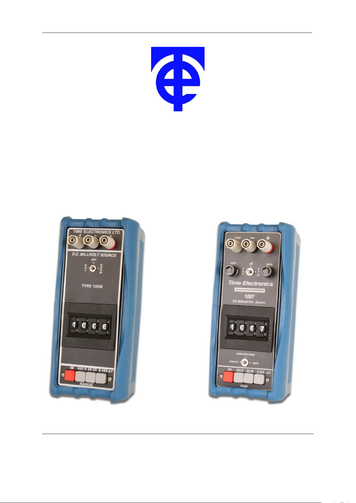
1.1. 1006 DC Millivolt Source
• 3 Ranges
0-1V (0.1 mV steps)
0-100mV (10 uV steps)
0-10mV (1 uV steps)
• 0.02% Accuracy
• 20mA Output Current
• Short Circuit & Overload Protected
• Battery Powered – Portable
• Safety Terminals
• Battery Level Indicator
The 1006 is an accurate low cost millivolt source suitable for voltage injection applications.
Three output ranges are provided to give adjustable output values from 1µV to 1V with a
basic 0.02% accuracy. For signal injection, the operator needs to switch on, check the
battery condition, select the range, and set the required voltage using the thumbwheel
switches. The 1006 uses a precision reference diode and low temperature coefficient
resistors to give a highly stable output.
Power is provided by 6 AA batteries. Battery life is several months, depending on usage.
The battery condition is monitored by an indicator mounted on the top of the unit. The 1006
has up to 20mA drive current and is short circuit and overload protected.
An off/normal/reverse output polarity switch is provided.
Operation: The 1006 is simple to operate and does not require standardisation or
calibration prior to use. For signal injection, the operator needs only to switch on, check the
battery condition and select the required range output.
1006/1007 Technical Manual
3
Page 4
4
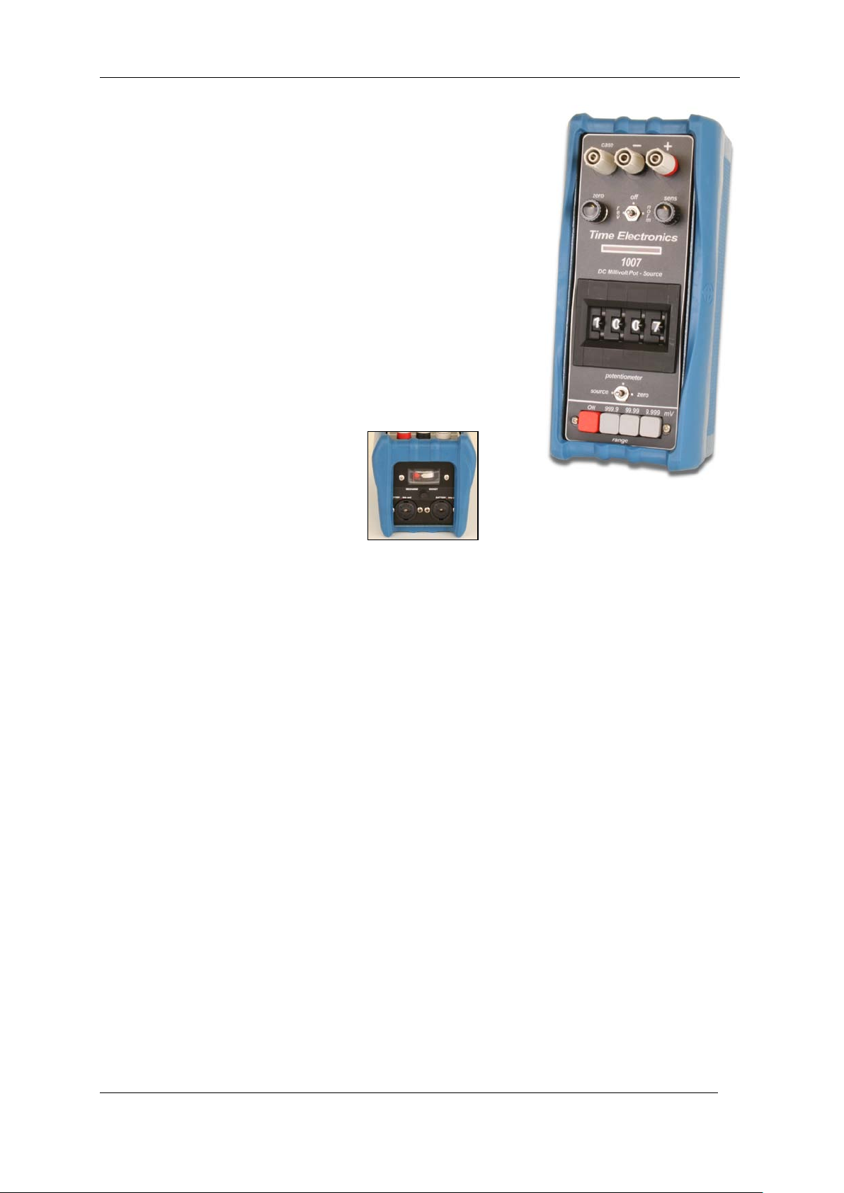
1.2. 1007 Millivolt Potentiometer and Source
• 3 Ranges
0-1V (0.1 mV steps)
0-100mV (10 uV steps)
0-10mV (1 uV steps)
• 0.02% Accuracy
• 1 Micro-Volt Resolution Null
• No Standardisation Required
• Millivolt Source Operation as 1006
• Safety Terminals
• Battery Level Indicator
The 1007 includes all the features of the 1006 with the addition of a microvolt null balance
display. This enables it to be used for potentiometric voltage measurement in addition to its
function as a calibrator. The null zero and sensitivity are adjustable via front panel controls maximum sensitivity enables null balance to resolve 1 microvolt.
Applications are essentially those of conventional potentiometers with the following
significant advantages:
1. No Standardisation is required.
2. 20mA output current.
3. Output remains stable without re-adjustment.
4. Electronic null with microvolt sensitivity.
Operation: The 1007 is simple to operate and does not require standardisation or
calibration before use. It is only necessary to zero the null amplifier prior to making a
measurement.
1006/1007 Technical Manual
4
Page 5

5
2. Specifications
Output: 0.999.9mV in 3 ranges
0.999.9mV in 0.1mV steps
0.99.99mV in 10uV steps
0.0.999mV in 1uV steps
Accuracy: ± 0. 02% of set ting
± 0.02% of range
Output Resistance: Less t han 0.1 ohm on 1V and 100mV ranges.
1 ohm on 10 mV range.
Maximum Output Current: 1V and 100mV ranges - 20mA.
10mV range: Up to short circuit value althoug h it should be
noted that loads of less than 1K ohm will give greater than
0.1% error.
Output Voltage Stability: Less than 60ppm/°C.
Less t han 100ppm per 3 month. (non cumulative)
Operating Temperature: -10°C to + 60°C.
Output Polarity: Positive or negative switch selected. A centre ‘off’ position is
also provided.
Output Noise Level: Less than 30ppm of f.s.
Reference Source: Precision zenor diode selected for stability and low
temperature coefficient.
Maximum Overload: The instrument can withstand continuous short circuit on the
output f or all ranges.
Power Supply: 6 AA batteries. A battery condition display indicates when the
batteries should be changed. An alternative power source is 6
NiMH cells of t he same dimensions - these can be recharged
via a socket on the top of the unit. The 6 rechargeable
batteries and mains re-charger unit are available as an
optional extra.
Null Balance Display: The null display is on a front panel meter, zero and sensitivity
(1007 only) cont r ols are provided.
Maximum sensitivity: ± 20uV fsd (2uV/div.)
Minimum sen s itivity: ± 20-0-20(20 divisions).
Input resistance: Greater than 1M ohm at balance.
Dimensions: 200 x 75 x 110mm (215 x 100 x 120mm incl. protective boot)
Weight: 1.1kg (1.5kg incl. protective boot)
1006/1007 Technical Manual
5
Page 6

6
3. Operating Instructions
The 1007 incorporates a 1006 with the addition of a microvolt null detector and enables the
unit to be used for potentiometric measurements. The additional front panel components
are:
1) Null Balance Meter
2) Null Zero Adjust Control
3) Null Sensitivity Adjust Control
4) Function Switch marked SOURCE:POTENTIOMETER:ZERO
3.1. Battery Insertion
To insert batteries, remove two black covers on top of the instrument by pressing in and
turning 90° anti-clockwise. Three size AA batteries should be inserted in each tube with the
positive (tip) terminal upmost. Note that if the optional battery charger is to be used, then
nickel metal hydride (NiMH) rechargeable batteries must be used in the instrument.
3.2. 1006 Operation
Switch on supply (push button) and check the battery level. The battery level indicator is
mounted on the top (terminal end) of the unit, with a minimum line indicating when the
batteries should be replaced or recharged. Select required range with push button and dial
required output voltage. The output voltage polarity can be selected on the front panel
switch - the centre position disconnects the output and provides a short circuit on the
output terminals.
3.3. 1007 Operation
1) Millivolt Source Operation:
Operation is as the 1006 when the function selector switch is in “SOURCE” position. The
only difference being that the “OFF” position on the polarity voltage switch provides open
circuit on the output terminals - this is to prevent accidental shorting of the voltage under
test when the unit is being used as a potentiometer. It is desirable to keep the Null
“SENSITIVITY” control set to minimum (fully anti-clockwise) when the unit is being used as
a source.
2) Millivolt Potentiometric Null Operation:
Due to the extreme sensitivity of the electronic null detector (2uV/div.) it is important to
ensure that it is correctly zeroed before attempting accurate measurements.
Zero setting procedure:
a) Set function switch to ZERO.
b) Set RANGE switch to required position.
c) Sensitivity (SENS) to maximum (f ully clo c kwise).
d) Adjust ZERO control for zero reading on null meter.
Measuring procedure:
a) Set function switch to POTENTIOMETER.
b) Set output polarity switch to NORM.
c) Set sensitivity (SENS) to minimum (f u lly counter clockwise).
d) Connect unknown voltage to output terminals (in the same polarity).
e) Adjust output digits and sensitivity for a null balance as required.
1006/1007 Technical Manual
6
Page 7

7
3.4. Internal Preset Controls
IMPORTANT NOTE:
These controls are set in the factory before shipment and normally will not require
readjustment.
If readjustment is considered necessary, it is important to check that the amount of
adjustment required is within the range of the trimmer concerned. If it is greater than the
trimmer range, there is no point in attempting to readjust and a fault condition will exist in the
unit. The range of adjustment of the trimmers is given below.
Access to the 1006 or 1007 is by removing the blue cover which is located by 8 screws.
1006 Millivolt Source
The 1006 contains 3 (4 on instruments with serial number greater than 1320) internal preset
trimmers. They are located on the module p.c.b. which also contains the range switches.
Zero
The ‘ZERO’ trimmer adjusts the circuit zero and is set to bring the output voltage (with all
digits set to zero) within the specified limits.
Calibration
The 1V and 100mV ‘CAL’ trimmers adjust the full scale calibration (i.e. 9999) on the 1V and
100mV ranges respectively to within the specified limits. Instruments later than No. 1320
have an additional trimmer for the 10mV range.
It is important to set the ZERO before attempting CALIBRATION.
Test Equipment Required
1) A microvoltmeter with a resolution of better than 5 microvolts. The null amplifier section of
Time Electronics 1007 can be used although any suitable microvoltmeter or sensitive
D.V.M. may be used.
2) An accurate dc voltage source with a range 0-1V and accuracy better than 0.02%. A
Time Electronics 1010 is suitable. Alternatively a high performance D.V.M. can be used.
Zero Setting Procedure
1) Switch unit on and check battery condition is good.
2) Select 99. 99 mV range and set all digits to zero.
3) Select ‘NORMAL’ output polarity.
4) Connect microvoltmeter to output and adjust ZERO trimmer for less than - 10uV reading.
The maximum amount of adjustment available on this trimmer is approximately ± 100uV.
5) Check the zero reading for other ranges. The readings should be as follows:
9.999mV range less than ± 2uV
99.99mV range less than ± 10uV
999.9mV range less than ± 100uV
1006/1007 Technical Manual
7
Page 8

8
Calibration Procedure
1) Check zero output is correct as described on Page 6.
2) Select 999.9 mV range and ‘normal’ output polarity.
3) Set output digits to 9999.
4) Connect the accurate voltage source and microvolt null meter to the 1006 output in a
potentiometric mode.
5) Set the voltage source to 999.9mV output and adjust the ‘1V CAL’ trimmer on the module
to bring the 1006 output within specification. The maximum amount of adjustment
available on this trimmer is 0.8%.
6) Select 99.99 mV range on the 1006 and set the voltage source to 99.99 mV. Adjust the
‘100mV CAL’ trimmer to bring the output within specification. The maximum amount of
adjustment available on this trimmer is 0.8%.
7) The specified allowable errors for these two ranges are:
999.9mV range less than ± 550uV at f.s. output
99.99mV range less than ± 55uV at f.s. output
8) The 9.999mV range is obtained by resistive attenuation of the 999.9mV range. A 100:1
attenuation ratio is used and adjustment is by preselected resistor values. Unless
overload damage to the attenuator resistors has occurred, the calibration of the 1 volt
range will automatically ensure the calibration of the 9.999mV range. The specified
allowable error for this range is ± 6uV at f.s. output.
Note: All instruments with serial numbers later than 1320 incorporate an additional single
turn trimmer to adjust the f.s. calibration of this range.
1006/1007 Technical Manual
8
Page 9

9
1007 Millivolt Source and Potentiometer
The 1007 incorporates a 1006 with the addition of a microvolt null detector. With the front
panel function switch in the ‘SOURCE’ position, the unit operates as a 1006 and the ZERO
and CALIBRATION setting procedures are identical to those for the 1006.
The potentiometer position of the function switch connects a high performance null balance
system in series with the output. The null zero and sensitivity are adjustable by front panel
controls. Maximum sens. = ± 25uV. Min. sens. = ± 250mV and zero adjust range is
approximately ± 100uV.
The null amplifier circuitry is located on a small p.c.b. which is fixed to the underside of the
output terminals. The circuitry incorporates two preset trimmers for adjustment of the null
amplifier input voltage and current offsets.
Important Note: It is important to check that the 1007 is operating correctly as a
millivolt source and that the source zero setting is within specification before
considering readjustment of the null amplifier trimmers.
Null Amplifier trimmer adjustment procedure
Voltage Offset (10K trimmer):
1) Select ’ZERO’ position on the function switch.
2) Set all digits to zero. Select 9.999mV range.
3) Adjust trimmer for equal swing (about zero) of the front panel zero control.
Current Offset (500K trimmer) :
1) Select ’ZERO’ function, all digits zero, 9.999mV range.
2) Select potentiometer operation.
3) Connect a 47K ohm Resistor across output terminals.
4) Adjust trimmer for zero reading on the null display - the null sensitivity can be increased
gradually to maximum during adjustment.
Note: A low offset current is important when measurements are to be made in high
resistance circuits, but will not affect accuracy of measurements in low resistance circuits.
1006/1007 Technical Manual
9
Page 10

10
4. Guarantee & Servicing
Guarantee Period
This unit is guaranteed against defects in materials and workmanship for a period of one
year from its delivery to the customer.
We maintain comprehensive after sales facilities and the unit can, if necessary be returned
to us for servicing. During this period, Time Electronics Ltd will, at its discretion, repair or
replace the defective items. For servicing under guarantee, the instrument type and serial
number must always be quoted, together with details of any fault and the service required.
The purchaser of the instrument must prepay all shipping charges. Time Electronics Ltd will
pay return shipping charges.
This guarantee is void if servicing has been attempted by an unauthorised person or agent.
If, during the guarantee period, failure is due to misuse or abuse of the unit, the repair will be
put in hand without delay and charged unless other instructions are received.
Service After Guarantee Period
Even after the guarantee period has expired, Time Electronics Ltd., can still service your
instrument. As the manufacturer, we have the specialised knowledge needed to keep your
instrument in peak condition and we also maintain a comprehensive spare parts service.
Please enclose details of the service required and your full company details including a
contact name when returning for servicing.
Returning Instruments
When returning instruments, please ensure that they have been adequately packed,
preferably in the original packing supplied. Time Electronics Ltd will not accept
responsibility for units returned damaged. Please ensure that all units have details of the
service required and all relevant paperwork.
Send the instrument, shipping charges paid to:-
Botany Industrial Estat e, Tonbr i dg e, K ent, TN9 1RH
Tel: +44(0)1732 355993 Fax: +44(0)1732 770312
Email: mail@TimeElectronics.co.uk
Web Site: www.TimeElectronics.c om
Disposal of your old equipment
1. When this crossed-out wheeled bin symbol is attached to a product it means the
product is covered by the European Directive 2002/96/EC.
2. All electrical and electronic product s s houl d be disposed of separately from the
municipal waste stream via designated collection facilities appointed by the
government or the local authorities.
3. The correct disposal of your old appliance will help prevent potent i al negative
consequences for the environment and human health.
4. For more detailed information about dispos al of your old appliance, please cont act
your city office, waste disposal service or return to Time Electronics.
Time Electronics Ltd
1006/1007 Technical Manual
10
 Loading...