

Time domain PulsON 200 Getting Started Manual

Getting Started Guide Getting Started Guide
TM
PulsON 200
TM
UWB Evaluation Kit PulsON 200
UWB Evaluation Kit
P200-320-0048A
November 2002
Time Domain Corporation
Cummings Research Park
7057 Old Madison Pike
Huntsville, AL 35806 USA
http://www.timedomain.com
Tel: +1 256.428.6333
+1 888.826.8378 ext 6333
Fax: +1.256.922.0387
Proprietary Information: Do not disclose unless authorized under the the PulsON Developers Program Nondisclosure Agreement

Getting Started Guide
2
Nondisclosure Provisions
This manual contains Time Domain Corporation’s Confidential and Proprietary Information. Members of the
TM
PulsON
Confidential and Proprietary Information.
Developer’s Program and the PulsON
TM
Technology Program are reminded of their obligations to protect TDC
Copyright
2001-2202 Time Domain Corporation. All rights reserved.
Trademarks
Time Domain® and PulsON® are registered trademarks of Time Domain Corporation. Ethernet® is a registered trademark
of Xerox Corporation. Microsoft® and Windows NT®, 2000®,98® and ME® are registered trademarks of Microsoft
Corporation. Xilinx® is a registered trademark of Xilinx, Incorporated. “PulsON Triangle” logo, PulsON Technology
Program™ and PulsON 200™ are trademarks of Time Domain Corporation. MultiLINX™ is a trademark of Xilinx,
Incorporated. VxWorks
trademark of Intel Corp. Any trademarks, trade names, service marks or service names owned or registered by any other
company and used in this manual are the property of its respective company.
TM
is a registered trademark of Wind River Systems, Inc. HyperTerminal is the registered
Rights
Rights to use this documentation are set forth in the Terms and Conditions accompanying the Evaluation Kit
Regulatory Notice
This device does not comply with any RF emissions regulations in any country. Users should consult their spectrum
management authorities before use.
• U.S Operation
conditions: (1) this device may not cause harmful interference; (2) this device must accept any interference received,
including interference that may cause undesired operation; (3) this device must be operated indoors; and (4) the
emissions from equipment operated under this section shall not be intentionally directed outside of the building in
which the equipment is located, such as through a window or a doorway, to perform an outside function, such as
detection of people about to enter a building. Operation in disregard of these conditions is a violation of 47 U.S.C. 301
and could subject the operator to serious legal penalties
• If you have questions, please consult with Time Domain Corporation before you use this device.
• Non-U.S.:
any government agency. Please confer with your government’s regulatory agency to ensure proper authorizations are
obtained.
: This device complies with Part 15 of the FCC Rules. Operation is subject to the following
PulsON® technology has not been authorized for use or commercial exploitation under the regulations of
Proprietary Information: Do not disclose unless authorized under the the PulsON Developers Program Nondisclosure Agreement
Getting Started Guide
Introduction
Congratulations on stepping in to the world of Ultra Wideband (UWB) technology! The Evaluation
Kit (EVK) is the key hardware tool for UWB evaluation and application development. Within the
next thirty minutes, this guide will help you set up, configure and test your PulsON 200
The initial functionality of the EVK includes tools to examine the performance of the PulsON 200
radio and a development environment that allows users to explore the possibilities provided by UWB.
This Getting Started Guide takes the user from initial radio setup through first power-up and to the
radio connection to the computer interface. At the completion of this guide, you will have confirmed
that the radios are functional and the correct setup configuration between the radios and the user’s
computer.
TM
radios.
3
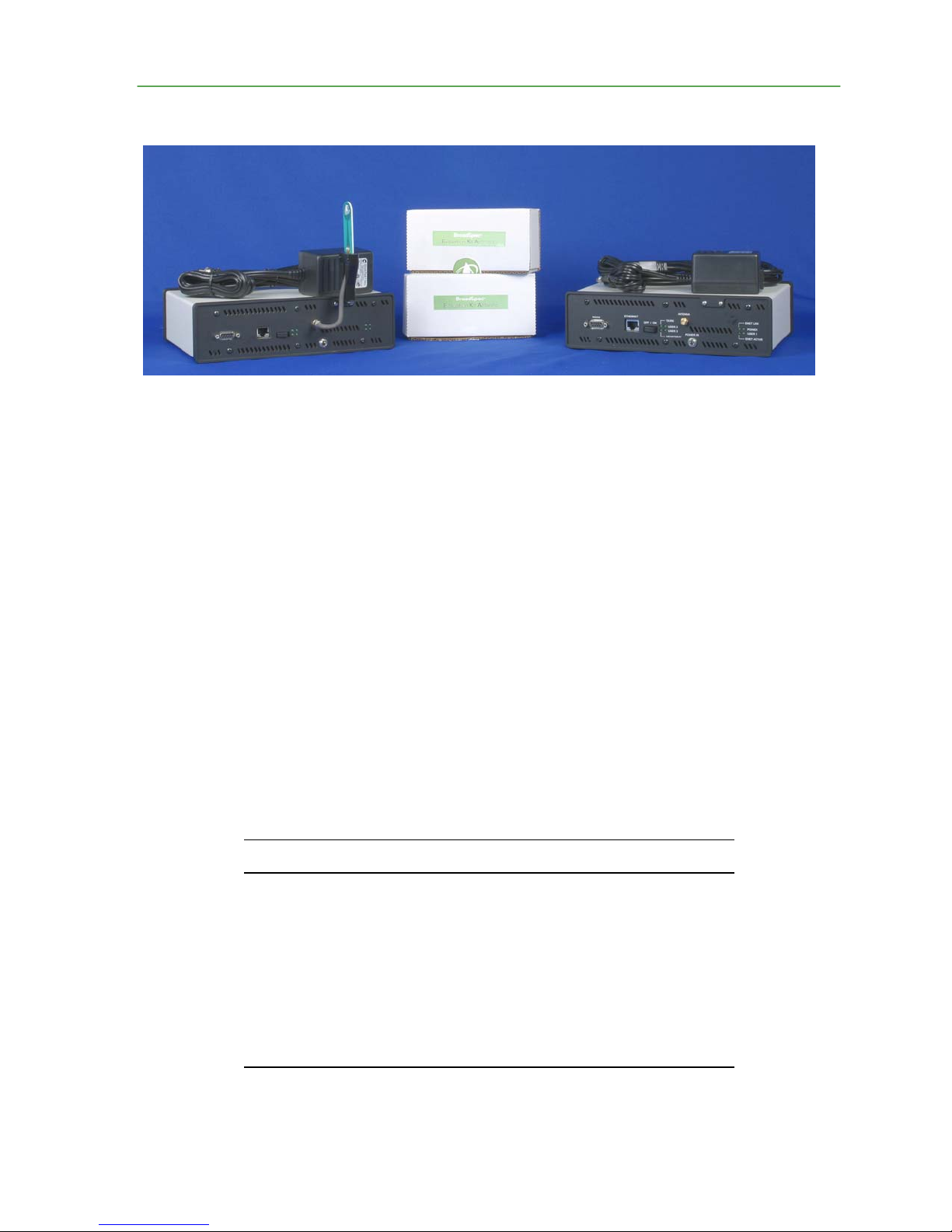
What is in the box?
Upon receipt of your shipment, inspect the shipping container and contents. If the contents of the
shipment are incomplete or if there is mechanical damage, notify Time Domain Corp. (TDC)
immediately at 1-800-826-6333. TDC has supplied the following items with your shipment.
Qty. Name Part #
2 PulsON 200TM Radio 100-0017
2 Broadspec® Model P200 Antenna, EVK 220-0126
2 Power Supply, 90-264 VAC in/7.5 VCD out 024-0003
2 Power Cord 017-0029
1 Software CD 150-0015A
1 Documentation CD 10D-0014A
Table 1: Supplied components of the Evaluation Kit
Proprietary Information: Do not disclose unless authorized under the the PulsON Developers Program Nondisclosure Agreement

Getting Started Guide
4
The software CD (150-0014A) contains a copy of the embedded elements already loaded on your
radios as well as the necessary PC software. These elements include:
• UWB Kernel (in executable form)
• Performance Analysis Tool (PAT) embedded (in executable form)
• PAT GUI (Self-extracting executable)
• Basic Host Translator (Host API)
• Flash Loader Utility
The embedded code is provided should the radio software need to be reloaded. The Troubleshooting
the Radio section of this Guide provides instructions for this software load. Instructions on loading
the PAT GUI appear in this document.
The documentation CD (10D-0015A) contains this document as well as the PulsON
Evaluation Kit Users’ Manual (P200-320-0049) and the Programming Guide for the PulsON 200
TM
200 UWB
TM
Evaluation Kit (P200-320-0050A). Updates to these documents will be provided as functions are
added.
What You Will Need to Work with the Unit
TM
In order to connect to and control the PulsON 200
hardware, and software as described below.
• PC running Windows 2000 or Windows NT-- EVK software has been developed to
work with Windows 2000 and Windows NT. The EVK software will work with Windows
98 and Windows ME operating systems, but the Flash Loader Utility will not. Windows
98 and Windows ME should not be used with this device.
• Dedicated 10/100 Mbps Ethernet Network Interface Card-- Each PC used to control a
PulsON 200 radio should be configured with a 10/100 Mbps Ethernet Network Interface
Card (NIC) configured for dedicated communication with the radio. If the PC already has
a NIC installed to provide LAN access, a second NIC card should be installed and
configured for communication with the radio. See Installing and Configuring an Ethernet
Network Interface Card in the Troubleshooting the Radio appendix of this document for
the setup procedure.
• Ethernet Cables-- CAT-5 Standard or Crossover Ethernet cables will be needed to
connect a PC to the PulsON 200 radio. Refer to section PC-to-PulsON 200 Radio
Ethernet Connection Options of this document for information on specific configurations.
• Ethernet Hub—An Ethernet hub may be required to connect a PC to one or more PulsON
200 radios. Refer to section PC-to-PulsON Radio Ethernet Connection Options of this
document for more information.
radios,
the user will need at least one PC,
Proprietary Information: Do not disclose unless authorized under the the PulsON Developers Program Nondisclosure Agreement

Getting Started Guide
• RS-232 Cable (optional) A DB9 male-to-female RS-232 cable is needed if the user intends to
communicate with the PulsON 200 using a terminal application ( e.g. `HyperTerminal’)
running on a PC. Examples of RS 232 use include Built-In Test (BIT) results and radio
internet protocol (IP) address modification. Both topics are covered later in this document.
5
Configuring the Hardware
Please be careful when you remove the units and the antenna assemblies from their boxes. The
antenna solder joint between the antenna plane and the end-launch connection can be damaged if
handled improperly. Please inspect this connection and contact TDC if there appears to be a problem.
Also inspect the PulsON 200 radios for damage, including loose or missing screws. Contact TDC if
there is a problem.
1. Using a Phillips-head screwdriver, attach the Broadspec™ Model P200 antennas to the
antenna brackets on the rear of the units.
2. Connect the antenna cable to the port labeled ANTENNA. The antenna is omnidirectional. Once connected, do not adjust the antenna orientation as it may overstress the
attached cable through unnecessary bending.
Use of another antenna element other than the one provided in the kit is a violation of FCC rules
governing the transmission of UWB signals
Ensure that the cable connector nut is firmly tightened over the connection to avoid accidental
disconnection. Do NOT over-tighten. Seven to ten inch-pounds torque using an approved connector
wrench (Huber & Suhner, part number 74Z0-0-21 or equivalent) is recommended. The connector
center pins on the cables are fragile. If you meet resistance when connecting a cable to a port, either
during insertion or when tightening the connector nut, do not force the connection. Abort this attempt
and try again. Damage to the connecter caused by over-tightening is not covered by the warranty.
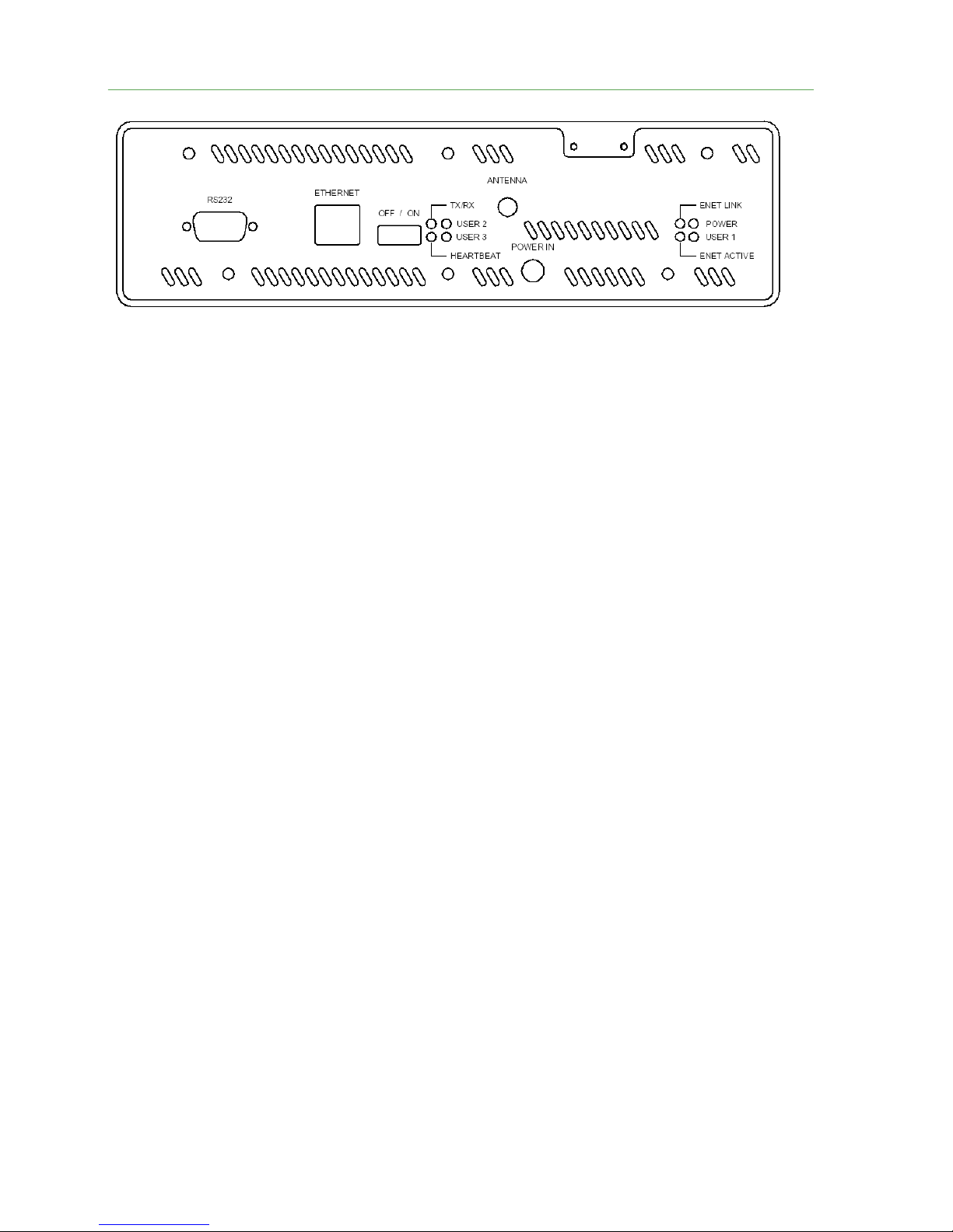
3. Connect the supplied power supply to the POWER IN interface (Fig. 1).
Initial System Power-Up
The radio is now ready to be powered on. To turn the radio on, place the power switch on the rear
panel in the ON position. The rear panel LEDs will activate in the following sequence:
1. As soon as the power switch is placed in the “on” position, the LED on the right side labeled
POWER will turn on and remain lit with a steady glow.
2. Almost immediately after the POWER LED turns on, the LED labeled HEARTBEAT will turn
on and remain lit with a steady glow.
Proprietary Information: Do not disclose unless authorized under the the PulsON Developers Program Nondisclosure Agreement
Getting Started Guide
6
Fig. 1: Rear panel of the PulsON 200 radio
3. After several seconds, if an Ethernet cable is connected and an Ethernet network connection exists,
the ENET LINK LED will turn on and remain lit with a steady glow. It may blink briefly before
becoming steady.
4. After several seconds, the TX/RX LED will turn on and glow steadily, indicating the radio is
configured for transmit mode. This does not mean the radio is actively transmitting. In the default
power-on condition, the radio configures itself for transmit mode and then idles until it is given a
"start" command.
5. After several seconds, the HEARTBEAT LED will begin to blink to indicate the status of the
Built-In Test (BIT) initiated at power up .
• If HEARTBEAT blinks at a 1 Hz rate, then BIT has passed. Proceed to the PC
Configuration section of this document.
• If the HEARTBEAT blinks at a fast rate (approx. 10 Hz), or shows other behavior, then
BIT has failed. Turn the radio OFF and then back ON. If the HEARTBEAT again
blinks at a fast rate, then the radio is reporting a BIT error. At this point, you have two
options. You can proceed to the PC Configuration section of this document and attempt
to make Ethernet connection to the radio. If you are successful, the Users’ Manual will
explain how BIT results can be collected using the Performance Analysis Tool (PAT).
Alternatively, you can use the RS232 interface to obtain the BIT results. The procedure
for doing this appears in the Troubleshooting the Radio appendix of this document.
PC Configuration
Loading the PC Software
Next you will need to install the Host portion of PAT on your computer.
1. Login as Administrator or with administrative privileges.
2. Insert the compact disk labeled “PulsON
disk drive. Set up should launch automatically. If it does not,
• Click the Start button, point to Settings, and then click Control Panel.
• Double –Click the Add/Remove Programs Icon
• On the Install/Uninstall tab, click Install
3. You should see a box as shown in Fig. 2.
Proprietary Information: Do not disclose unless authorized under the the PulsON Developers Program Nondisclosure Agreement
TM
200 EVK Software, Version 1.0” into your
 Loading...