

Page 1

General description
1
1.1 Scope of applications
The handheld microprocessor-controlled thickness gauge is designed for
measuring the thickness of metals, and non-metallic materials e.g. aluminum,
titanium, plastics, ceramics, glass and any other good ultrasonic wave-conductor
as far as it has two parallel surfaces on the top and bottom.
The TT100 can be used in industrial applications to perform precise
measurements on various kinds of new materials, parts and components, and it
can also be used to monitor various kinds of pipes and pressure vessels for the
decrease of their thickness due to corrosion and/or erosion.
1.2 Basic working principle
The principle of ultrasonic wave in the thickness measurement is similar to that of
optical wave. The ultrasonic wave pulses transmitted by the probe will be reflected
back, while they reach the interfaces. The thickness of the object is determined by
precisely measuring the time the ultrasonic wave travels in the object.
1.3 Basic configuration and each part description of the tester
1.3.1 Basic configuration:
main processor: 1 piece
probe: 1 piece
coupling agent: 1 bottle
1.3.3 The name of each part of the testing meter (see figure below):
1
Page 2
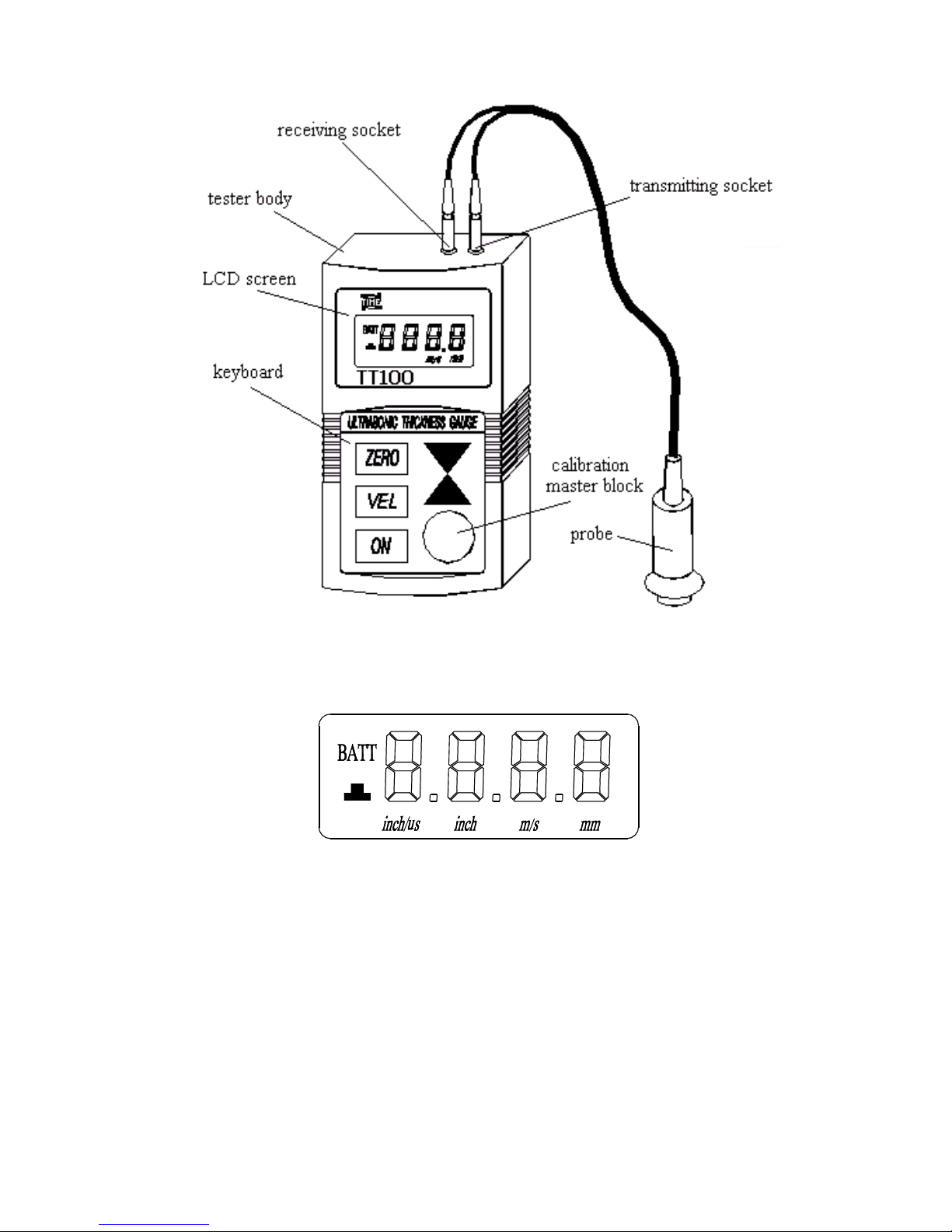
LCD screen display:
BATT : low voltage indication
凸 : coupling indication for satisfactory acoustic
coupling between probe and test piece
m/s : measurement unit of sound velocity
mm : measurement unit of thickness
Keyboard:
2
Page 3
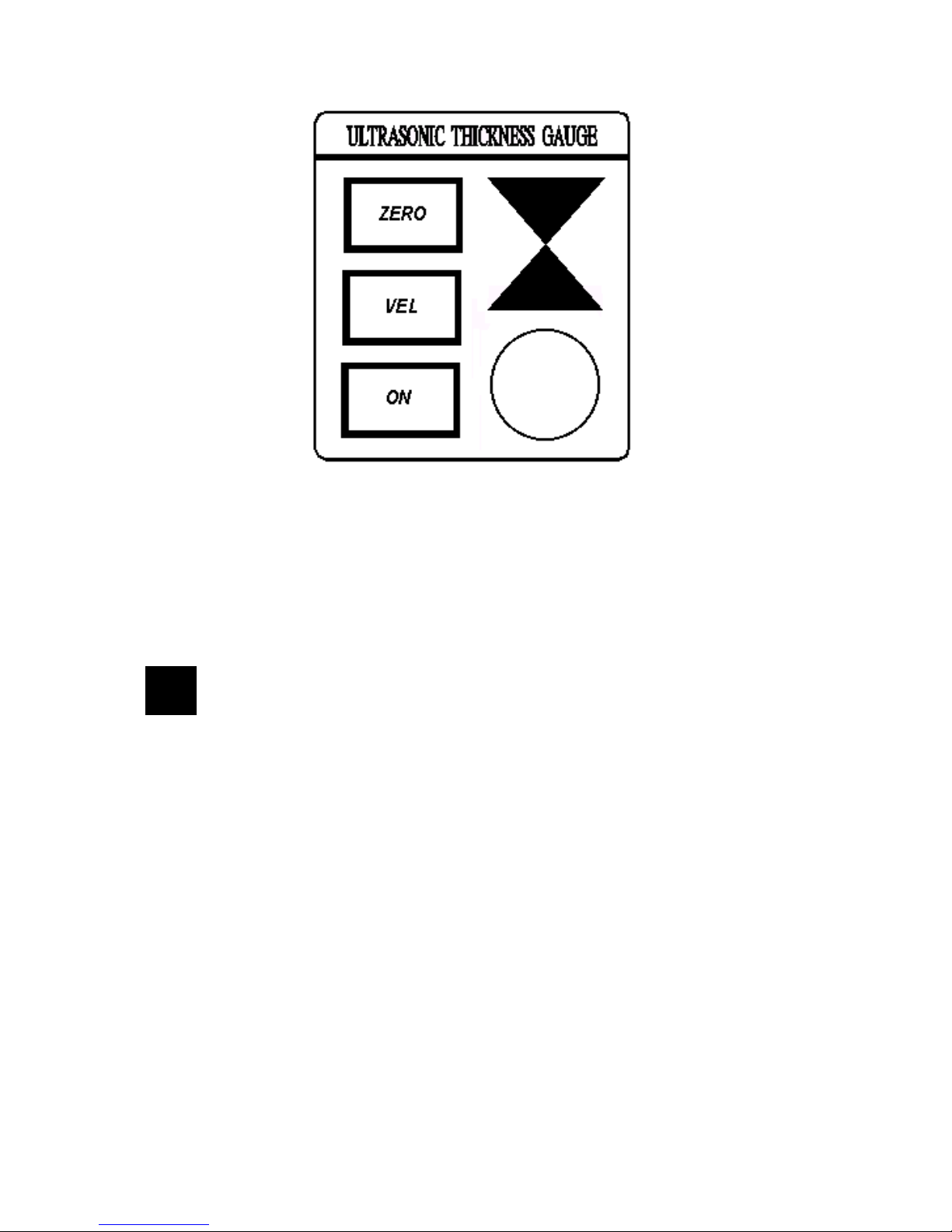
ON : power
ZERO: probe zero procedure
VEL : sound velocity value / 5 velocity are stored
▲-▼: adjustment keys for sound velocity, thickness, 10
memory units for thickness storage
2
Performance parameters
Display type: 4-digit LCD
Minimum display unit: 0.1 mm
Measuring range: 1.0mm – 225.0mm in steel (with standard
probe) (other maximum values depending
on material)
Lower limit for steel pipes: 20 mm × 3.0 mm
Display accuracy: ±0.1mm
Sound velocity range: 1000 – 9999 m/s
Coupling check: satisfactory / no probe coupling
Range of operating temperature: 0℃~40℃
Working frequency 5 MHz
Update rate: 4 Hz
Power supply: two AA alkaline cells 1.5V
Battery life: 250 hours with one battery set
Dimensions: 126×68×23mm
Weight: 170 g
3
Page 4
Main functions
1) Automatic probe zero adjustment: automatically correct the system errors
2) Automatic non-linear compensation: within the full range, computer software is
used to correct the non-linear errors of the probe for the purpose of improving
the accuracy
3) Keys ▲-▼ are used for fast adjustment of sound velocity and thickness as well
as fast checking the thickness memory unit
4) Calibration to known sound velocity
5) Calibration to a known thickness (the sound velocity can be directly determined
according to a known thickness, avoiding the trouble of looking into table.)
6) Ten different thickness values can be stored and held after switch-off
7) Coupling indication: the stability can tell if the coupling is normal
8) Sound velocity of five different materials can be stored
9) Indication at low voltage
10) Automatic switch off
11) Oil proof keyboard with longer service life
3
4
Measuring steps
4.1 Preparations for measurement
Connect the probe sockets to the connectors on top of the unit. Connect the
transmitting socket at the connector positioned at right, and the receiving socket to
the connection position left, holding the tester display in front.
Push On-key to turn on the unit.
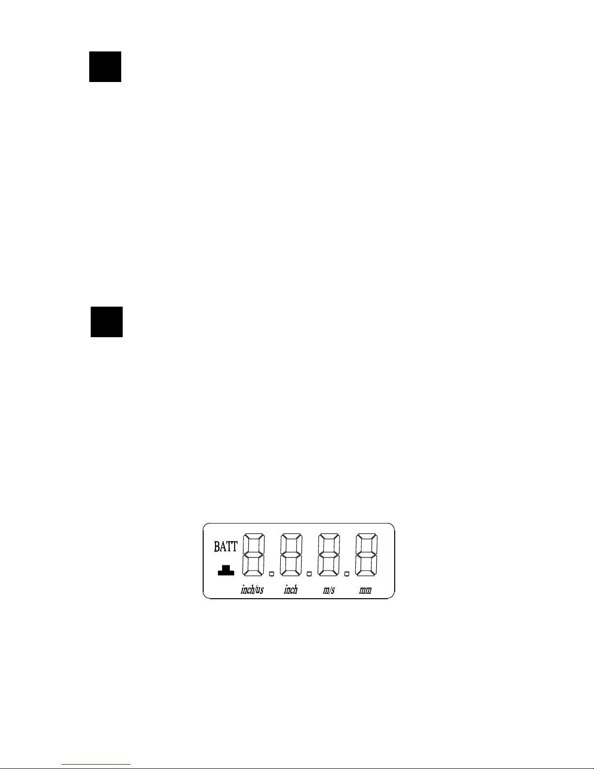
As it is shown in the figures below, after the full screen display for a few seconds, the
screen will display the sound velocity used last time. The measurement can start
now, but read other paragraphs first.
Full screen display
4
Page 5
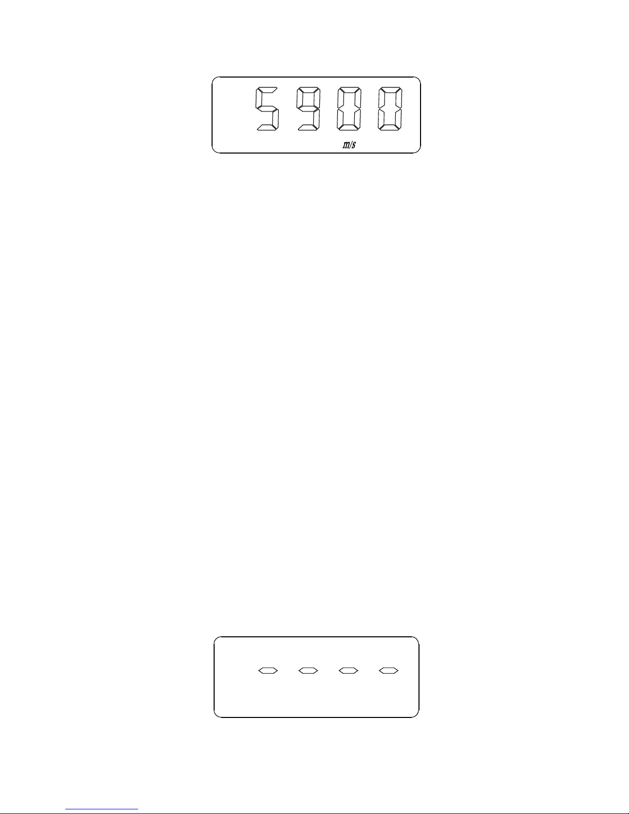
Sound velocity
Note: The surface of the probe is made of propylene resin and is very sensitive to
heavy scratches on rough surfaces, so in application, push the probe gently on the
surface.
Automatic turn off
If within two minutes no operation performed, the unit turned off automatically.
4.2 The adjustment of sound velocity
if the screen currently displayed the thickness value, then push the VEL-key to enter
into sound velocity state. The screen will display the content of the current memory
unit of sound velocity. Each time the VEL-key is pushed the sound velocity memory
unit will change. Five different sound velocity values will be displayed in turn.
If the current displayed sound velocity is desired to be changed, the keys ▲-▼ can
be used to adjust the to the desired value. This value will be stored automatically as
one out of fives stored velocities.
4.3 Calibration
Each time the probe or battery is changed, calibration should be performed. This
step is rather critical to secure the measuring accuracy. If necessary, calibration can
be repeated several times. Take following steps:
Put a little coupling agent on the steel master testing block on the unit, which has
a thickness of 4.0mm.
Adjust the sound velocity to 5900 m/s (steel) using the VEL-key and the keys ▲
-▼
Push the ZERO-key and enter into the state of calibration and then the screen
display:
5
Page 6
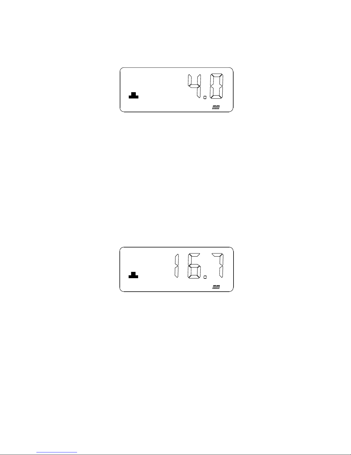
Coupling the probe with the testing block. At this time the bar lines displayed on
the screen will disappear one after the other until the screen displays 4.0mm.
This indicates that the calibration is over:
4.4 Calibration to a known velocity: thickness measurement
Put the coupling agent in the place to be measured.
Adjust the sound velocity depending on the material (see table in black). (If it is
not clear what the right sound velocity should be, for example when the material
is unknown or readings are not correct at a certain velocity, then first read
paragraph 4.5)
Couple the probe with the material to be measured.
The measurement can thus start. The screen will display the thickness of the
material to be measured, for example:
Note: When the probe couples with the material to be measured, the coupling
indication sign will be displayed on the left side at the display. If the coupling
indication flicks or does not appear, it shows that the coupling is not well done. Take
the probe away, the thickness value will remain and coupling indication will
disappear.
4.5 Calibration to a known thickness: sound velocity measurement
If it is desired to measure the sound velocity of a certain material, a testing block with
a known thickness must be used to measure the sound velocity as follows:
Use a vernier caliper or micrometer to measure the test piece thickness
6
Page 7
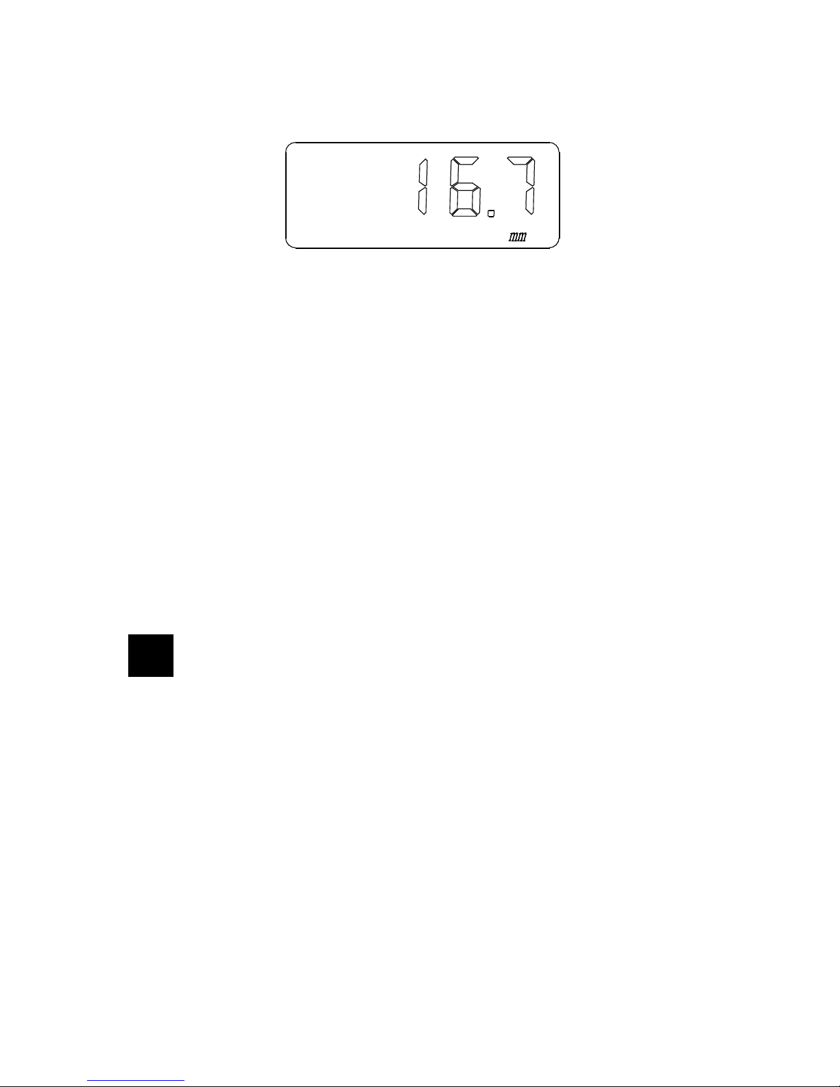
Couple the probe with coupling agent with the test piece with the known
thickness until a (wrong) thickness value is displayed:
Remove the probe.
Use keys ▲-▼ to adjust the displayed thickness value to the actual known
thickness of the testing block, for example 25.0 mm:
16.7 > keys ▲-▼ > 25.0
mm mm
Now push the VEL-key. The correct sound velocity for this material will be
displayed, and at the same time this sound velocity will be stored in the
current sound velocity memory unit:
25.0 > VEL-key > 6368
mm m/s
Start new thickness measurements on the same material with this velocity.
5
Memory of thickness value
5.1 Thickness memory state
Set the right sound velocity for a new measurement (see chapter 4).
Push and hold VEL-key and then push the ZERO-key to enter into the thickness
memory state.
The display will show a memory unit of a certain thickness: Unit 1 up to Unit 9.
Use the upper and down keys ▲-▼ to look for the required unit:
U1 > U2 > U3 > …… > U9
7
Page 8

While measuring the thickness, the value measured will be stored in the chosen
unit automatically. Each time a new value is measured, the old value in this unit
will be automatically replaced.
U1 >> 3.0
mm
Push the VEL-key once more to leave the thickness memory state.
5.2 Reviewing the thickness memory units
Push and hold the VEL-key and then push the ZERO-key to enter the thickness
memory
The display will show a memory units of a certain thickness: Unit 1 up to Unit 9.
Use the upper and down keys ▲-▼ to look for the required unit:
U1 > U2 > U3 > …… > U9
Again press and hold the VEL-key and press ZERO-key to show the stored
reading:
U1 > VEL + ZERO > 3.0
mm
Push the VEL-key to leave the thickness memory state.
6
Maintenance
6.1 Low voltage indication
If BATT is displayed on the screen, it shows that the battery voltage is running low
and the batteries should be replaced in time before the unit can be used again.
Battery replacement:
A. Wait until the unit turns off automatically.
B. Open the battery compartment (use the thumb to press down the compartment
cover and slide it out).
C. Remove the used batteries and put in new batteries. Note the polarity of the
battery.
6.2 Precautions
The surface of the probe is made of propylene resin and is very sensitive to
heavy scratches on rough surfaces, so in application, push the probe gently on
the surface.
8
Page 9

The temperature of the surface of the object to be measured should not exceed
60
o
C, otherwise the probe will not be workable.
Dust, iron chips, and carbon particles will cause trouble; keep unit clean all the
time.
Grease, oil and dust will make the cable of the probe aged and cracked,
therefore, after the use, the cable should be cleaned of dust and dirt.
If the unit is not to be used for a long time, remove the batteries.
Strictly avoid any collision or damp environment, etc.
7
Table of sound velocity of various materials
Materials Sound velocity (m/s)
Aluminum
6260
Zinc
4170
Silver
3600
Gold
3240
Tin
3230
Steel
5900
Brass
4640
Copper
4700
SUS
5790
Propylene resin
2730
Water(20oC)
1480
Glycerine
1920
Water glass
2350
9
 Loading...