


Ultrasonic Thickness Gauge
TT130
Content
TIME Group Inc.
Beijing TIME High Technology Ltd.

2
1. GENERAL DESCRIPTION ................................................................................................... 3
1.1 SCOPE OF APPLICATION........................................................................................................ 4
1.2 BASIC WORKING PRINCIPLE.................................................................................................. 4
1.3 BASIC CONFIGURATION AND EACH PART DESCRIPTION OF THE TESTER ................................ 4
2. PERFORMANCE PARAMETERS........................................................................................ 6
3. MAIN FUNCTIONS...............................................................................................................7
4. MEASURING STEPS..............................................................................................................7
4.1 PREPARATIONS FOR MEASUREMENT..................................................................................... 7
4.2 THE ADJUSTMENT OF SOUND VELOCITY ............................................................................... 8
4.3 CALIBRATION ...................................................................................................................... 8
4.4 MEASUREMENT OF THICKNESS:............................................................................................ 9
5. SWITCH BETWEEN METER AND INCH........................................................................ 10
6. SOUND VELOCITY MEASUREMENT ............................................................................. 10
7. MEMORY OF THICKNESS VALUES............................................................................... 11
7.1 MEMORY STATE................................................................................................................. 11
7.2 REVIEWING THE MEMORY UNIT.......................................................................................... 11
8. AUTOMATIC TURN OFF ................................................................................................... 13
9. MEASURING TECHNOLOGY...........................................................................................13
9.1 CLEANING THE SURFACE.................................................................................................... 13
9.2 LESSENING THE ROUGHNESS.............................................................................................. 13
9.3 ROUGHLY MACHINED SURFACE.......................................................................................... 13
9.4 CYLINDRICAL SURFACE ..................................................................................................... 13
9.5 COMPOUND CONTOUR........................................................................................................ 14
9.6 NON-PARALLEL SURFACE .................................................................................................. 14
9.7 TEMPERATURE EFFECT OF TEST MATERIAL ........................................................................ 14
9.8 HIGH ATTENUATION MATERIALS........................................................................................ 14
9.9 REFERENCE TEST BLOCK.................................................................................................... 14
9.10 A FEW MEASURING METHODS .......................................................................................... 15
9.11 SELECTION OF THE PROBE................................................................................................ 15
PROBE TYPE............................................................................................................................. 15
9.12 THE WEAR OF PROBE CROSS TALK ISOLATION BOARD MAY AFFECT THE RESULTS OF
MEASUREMENT
, PROBE SHOULD BE REPLACED WHEN THE FOLLOWING PHENOMENA OCCUR:..16
10. PREVENTION OF MEASURING ERRORS .................................................................. 16
10.1 SUPER-THIN MATERIALS .................................................................................................. 16
10.2 RUSTY SPOTS AND ERODED PITS....................................................................................... 16
10.3 ERROR IN MATERIALS IDENTIFICATION ............................................................................ 16
10.4 WEAR OF THE PROBE........................................................................................................ 16
10.5 USE OF THE ZERO-KEY ................................................................................................... 17
10.6 LAMINATED AND COMPOUND MATERIALS........................................................................ 17
10.7 THE EFFECT OF THE METAL OXIDE LAYER ........................................................................ 17
10.8 ABNORMAL READING....................................................................................................... 17
10.9 USE AND CHOICE OF COUPLING AGENTS........................................................................... 17

3
10.10 PROTECTIVE SHEATH OF PROBE...................................................................................... 17
11. PRECAUTIONS................................................................................................................... 18
11.1 AUTOMATIC TURN OFF..................................................................................................... 18
11.2 CLEANING OF TEST BLOCKS ............................................................................................. 18
11.3 CLEANING OF THE SHELL OF THE INSTRUMENT ................................................................ 18
11.4 PROTECTION OF THE PROBE.............................................................................................. 18
11.5 REPLACEMENT OF BATTERIES .......................................................................................... 19
11.6 STRICTLY AVOID ANY COLLISION OR DAMP ENVIRONMENT, ETC...................................... 19
12. MAINTENANCE.................................................................................................................19
13. NON-WARRANTY PARTS................................................................................................ 20
1. General description

4
1.1 Scope of application
Adopting the theory of ultrasonic wave measurement, TIME TT130 intelligent
Ultrasonic Thickness Gauge possesses the capability of thickness measurement for
various kinds of materials in which ultrasonic wave pulses propagate with a constant
velocity and reflect on the back interface.
The device can be used to perform accurate measurement for various kinds of
plates and parts. Another prominent characteristic of it is to monitor various kinds of
pipes and pressure vessels for the decrease of their thickness during the use
because of corrosion and erosion. TT130 enjoys a wide range applications in many
areas, such as petroleum, chemical engineering, metallurgy, shipbuilding, aviation
and spaceflight, etc.
1.2 Basic working principle
The principle of ultrasonic wave in the thickness measurement is similar to that of
optical wave. The ultrasonic wave pulses transmitted by the probe will be reflected
back, while they reach the interfaces. The thickness of the object is determined by
precisely measuring the time the ultrasonic wave travels in the object.
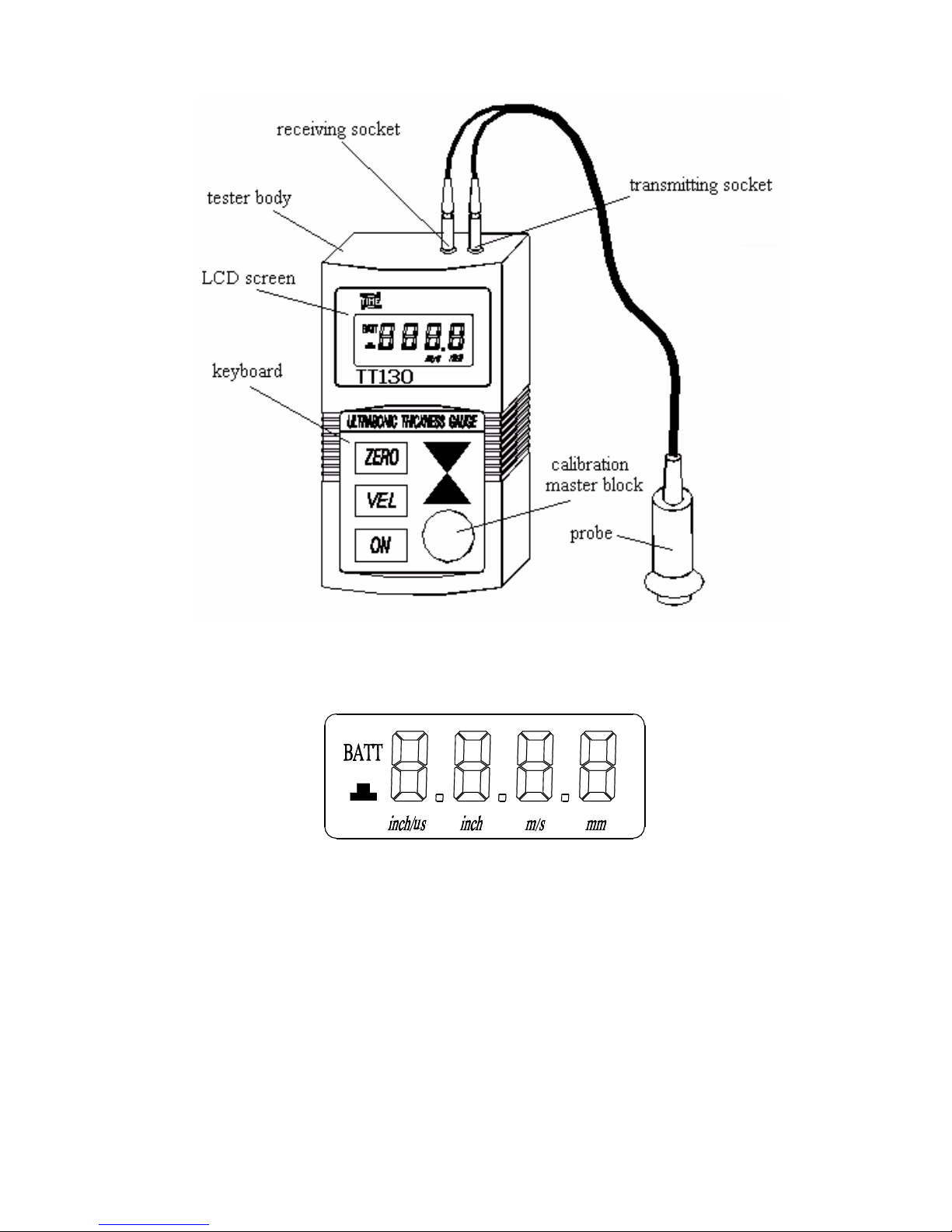
1.3 Basic configuration and each part description of the tester
1.3.1 Basic configuration:
main processor: 1 piece
5P10 probe: 1 piece
coupling agent: 1 bottle
1.3.2 Optional probes: 5P10/90 probe 1 piece
SZ2.5P probe 1 piece
7P6 probe 1 piece
1.3.3 The name of each part of the testing meter (see figure below):
5
LCD screen display:
BATT : low voltage indication
凸 : coupling indication
m/s : metric unit of sound velocity
mm : metric unit of thickness
inch/μs: imperial unit of sound velocity
inch : imperial unit of thickness
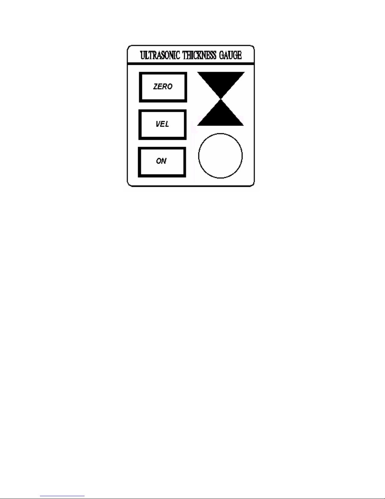
Keyboard:
6
ON : power
ZERO : calibration
VEL : sound velocity
▲ : adjustment key for sound velocity, thickness and thickness
unit
▼ : adjustment key for sound velocity, thickness and thickness
unit
VEL+ZERO : keys for thickness memory
2. Performance parameters
Display type: 4-digit LCD
Minimum display unit: 0.01 mm
Working frequency: 5 MHz
Measuring range: 1.2 mm~225.0 mm (steel)
Lower limit for steel pipes: Ф20 mm × 3.0 mm
Measuring error: ±(1%H+0.1) mm, H is the actual thickness
of the object to be measured.
Sound velocity range: 1000m/s~9999m/s
Velocity measurement according to a known thickness: measurement range is
1000m/s~9999m/s, the sound velocity measurement precision is 1mm/HX100 when
master block is 20mm thick and 5% precision with thickness of 20mm.
Range of operating temperature: 0℃~40℃
Power supply: two AA alkaline cells 1.5V
Power consumption: working current is smaller than 20mA (3V)
Dimensions: 126×68×23 mm
Weight: 170 g

7
3. Main functions
1) Automatic calibration to zero: automatically correct the system errors
2) Automatic non-linear compensation: within the full range, computer software
is used to correct the non-linear errors of the probe for the purpose of
improving the accuracy
3) The upward and downward adjustment keys enable prompt selection of
sound velocity, thickness, and check the thickness memory units
4) Prompt for coupling state: provide coupling indication and the observation of
the stability of the indication can tell if the coupling is normal
5) Ten thickness values can be stored without loss after turn-off, which is very
convenient for measuring in field and high platform
6) Measuring sound velocity: according to the test block’s thickness, sound
velocity can be measured directly needless to search in the conversion table
7) Sound velocity of five different materials can be stored
8) Low voltage indication
9) Automatic turn-off
10) All keys enclosed----oil proof for longer service life
4. Measuring steps
4.1 Preparations for measurement
Put the probe into the probe socket of the unit. Push ON-key to turn on the unit. As it
is shown in the figure below, sound velocity of last turn-off will be shown after the full
screen displays for a few seconds. The measurement can start now.
Full display screen

8
Sound velocity of last turnoff
4.2 The adjustment of sound velocity
If the screen currently displays the thickness values, then push the VEL-key to enter
into sound velocity state. The screen will display the content of the current memory
unit of sound velocity. Each time the VEL-key is pushed the sound velocity memory
unit will change. Five different sound velocity values will be displayed in turn. If the
current displayed sound velocity is desired to be changed, the keys △-▽ can be
used to adjust the display the desired value. This value will be stored automatically
as one out of five stored velocities.
Push VEL-key to enter into state of sound velocity
Value after adjustment by △-▽ key
4.3 Calibration
Each time the probe or battery is changed, calibration should be performed. This
step is rather critical to secure the measuring accuracy. If necessary, calibration can
be repeated several times.
Set the sound velocity to 5900m/s then push the ZERO-key and enter into the state
of calibration and then the screen display:

9
Put the coupling agent on the testing block supplied with the unit and couple the
probe with the testing block. At this time, the bar lines displayed on the screen will
disappear one after the other until the screen display 4.0mm (0.158inch). This
indicates that the calibration is over. Then enter the measurement state and
measure a random test block. If the measuring value error exceeds the
measurement error range, the calibration should be operated again until the
measuring value lies within the measurement error.
4.4 Measurement of thickness:
Put the coupling agent in the place to be measured and then couple the probe with
the material to be measured. The measurement can thus start. The screen will
display the thickness of the material measured. See the figure below:
Take the probe away, the thickness value will remain and coupling indication will
disappear. See the figure below:

10
5. Switch between meter and inch
5.1 When the power is off, press and hold ZERO button, press ON to
toggle between meter and inch.
5.2 When the power is on, if the current display is inch, press ZERO
for more than 5 seconds to toggle between meter and inch. Release
the button to end setting. If you hit the ZERO quickly, the calibrate
mode is on.
6. Sound velocity measurement
If the sound velocity in a certain kind of material is to be measured, a test block with
a known thickness is employed to measure the sound velocity. At first the accurate
thickness value should be obtained by using vernier calipers or micrometer. By
coupling the probe with the test block of known thickness, the screen will display a
thickness value, then remove the probe and adjust the shown value to the actual
one using the keys △-▽. Push VEL-key to get the desired sound velocity, at the
same time this sound velocity will be stored in the current memory unit. In sound
velocity measurement, the test block is required to be thick enough. The
recommended minimum thickness is 20mm.
Example: Measuring the sound velocity of material with the thickness of 25mm, the
operation procedure is as follows:
1. enter sound velocity state, a thickness value is displayed as:
2. Use keys
△-▽ to adjust the displayed thickness value to 25mm, just as the
following display:

11
3. Push the VEL-key, the sound velocity measured for this materials will be
displayed.
7. Memory of thickness values
7.1 Memory state
Push VEL-key and then ZERO-key to enter into thickness memory state and the
screen will show a memory unit of a certain thickness. Use keys △-▽ to set required
unit (use upward or downward keys can display unit0 to unit9 in turn). While
measuring the thickness, the value measured can be stored in the chosen unit.
Each time when a new value is measured, the old one in this unit will be
automatically replaced. The stored value in this memory unit is the latest
measurement value. Push VEL-key to leave the thickness state.
7.2 Reviewing the memory unit
Push and hold VEL-key and then push the ZERO-key to show current memory unit
number. Use keys △-▽ to look for required unit(using keys △-▽ can to display
unit0~unit9 in turn). Operate again to show the content of the memory. A new
measurement value can also be stored in this unit. Push VEL-key to exit thickness
memory state.
Example: Check the thickness value in memory unit 3

12
1. Push and hold VEL-key and then push ZERO-key, the display is as follows:
2. Use keys
△-▽ to find memory unit 3, the display is as follows:
3. Push and hold VEL-key and then push ZERO-key, the thickness value in
memory in unit 3 will be displayed:
4. Push VEL-key to exit. If leaving the thickness memory state without pushing
VEL-key, the new measurement value will replace the content of this memory
unit.
Low voltage indication
If BATT is displayed on the screen, it shows that the battery voltage is running low
and the batteries should be replaced in time before the unit can be used again.
7

13
8. Automatic turn off
If within two minutes no operation is performed, the unit turns off automatically.
9. Measuring technology
9.1 Cleaning the surface
Before measurement, it is necessary to clean the dust, dirt or rusty matters and
coatings of the surface off the test object.
9.2 Lessening the roughness
Too rough a surface may cause errors or no reading. Before measurement starts,
measures should be taken to keep the test surface smooth by way of grinding,
polishing and filing. High viscosity coupling agent may also be used.
9.3 Roughly machined surface
The regular fine furrows of roughly machined surface (such as machined by lathe or
planer) may also cause errors. The remedy method is similar to 9.2. Better result
can also be achieved by adjusting the intersectional angle between the probe cross
talk isolating board (the thin metal layer on the bottom center of the probe) and the
fine furrows of test materials (vertical or parallel). And select the minimum of the
readings as the accurate thickness of the materials.
9.4 Cylindrical surface
It is essential to select the right intersectional angle between the probe cross talk
isolating board and the axial line of the test materials in measuring materials with
Cylindrical surface, such as tubes or barrels. Simply speaking, make the probe
coupled with test materials and the probe cross talk isolating board and the axial line
of the test materials parallel or perpendicular and then gently shake the probe
vertically along the direct of the axial line of the test material, the reading will change
regularly. Select the minimum of the readings as the accurate thickness of the
materials.

14
The standard for the intersectional angle is determined by the curvature of the
material. For tubular material with bigger diameters, make the cross talk isolating
board perpendicular to the axial line of the tube; for tubes with a smaller diameters,
select two methods (making the intersectional angle parallel with and perpendicular
to the axial line) and select the minimum value of the readings as the thickness
measured.
9.5 Compound contour
In measuring materials with compound contour (such as elbows), the method
introduced in 7.4 may be used. The difference is that there is the need to measure
the second time to obtain two readings and take the smaller reading as the thickness
of the point measured.
9.6 Non-parallel surface
In order to obtain a satisfactory ultrasonic response, the other side of the test
materials must be parallel or on the same axial with the test surface. Otherwise,
there will be errors or no reading at all.
9.7 Temperature effect of test material
The thickness and ultrasonic wave transmission speed are all affected by
temperature. If a high accuracy is required, test block comparison method should be
employed. This method is to correct the measurement value by temperature
compensation coefficient obtained by measuring test blocks of the same materials
at the same temperature.
9.8 High attenuation materials
In the fiber, porous, large-grained materials, the ultrasonic wave will be scattered
and got energy attenuation, the above phenomena will cause abnormal display and
even no display (generally the abnormal displayed value is less than the actual one).
In this case, it’s not suitable to apply the gauge to this material.
9.9 Reference test block
For the calibration of the instrument, a test block with the thickness of 4.00mm is
configured on the TT130 cabinet, calibration method is scheduled in figure 4.3. The
attached test blocks are not enough for calibration while measuring different
materials on various conditions. The more similar the test block materials are to the
tested materials, the more accurate the measurement is. The ideal one is a series of
test blocks with different thickness. This series can offer device compensation
calibration coefficient (such as material microstructure, heat treatment condition,
grain orientation, surface roughness). It’s very important to possess a series of test
blocks to guarantee the maximum accuracy.
In most cases, only one test block is enough to get satisfactory measurement
precision. This test block should be of the same material and similar thickness to the

15
testing material. Select the testing material whose thickness is well-distributed and
measured by micrometer as a reference test block.
When the thickness of a thin material is close to the lower testing limit of the probe,
a test block can be employed to determine the exact lower limit (1.2mm for steel). Do
not measure the materials whose thickness is lower than the low limit. If the
thickness range can be estimated, the upper limit of the thickness of the test block
should be selected.
When the material is thick, especially alloys with complex microstructure, a similar
test block in the series should be employed for proper correction.
Most of the casting and forging are directional in internal structure. The speed of
sound may have a little change along different directions. In order to solve this
problem, the test block should have similar structure to the testing material. The
direction of the spread of sound in the test block should also be the same as the
testing material.
In some cases, look up the sound velocity of known materials for replacement of the
test block, but this can only approximately replace some of the test blocks. In some
cases, there are differences between the two values in the sound velocity table and
the actual one because of the difference in the physical and chemical properties of
material. This method is often used to test low carbon steel only for approximate
measurement.
Since TT130 ultrasonic wave gauge possesses the capability to measure sound
velocity, sound velocity can be obtained at first and then measurement of the part
can be undertaken according to this velocity.
9.10 A few measuring methods
a) single measuring method: measuring on one point
b) double measuring method: measuring two times on one point, make the cross
talk isolating board perpendicular to each other. Select the minimum display as
the exact thickness for the materials.
c) multi-point measuring method: measuring many times at a range of
measurement, select the minimum as the thickness of the material
9.11 Selection of the probe
Probe type
5PФ10 5PФ10/90 7PФ6 SZ2.5P
Frequency
(MHz)
5 5 7 2.5
Working
temperature
range
-10~60℃ -10~60℃ -10~60℃ -10~60℃
Measurement
range
1.2~225.0mm 1.2~225.0mm 0.75~60mm 3.0~300.0mm

16
9.12 The wear of probe cross talk isolation board may affect the results of
measurement, probe should be replaced when the following phenomena
occur:
1. The screen always displays the same measurement value while measuring
different thickness.
2. There is echo wave indication or measurement value displayed when the probe
has been inserted without measurement.
10. Prevention of measuring errors
10.1 Super-thin materials
Any material whose thickness is lower than the low limit of the probe will cause
measurement errors. Instrument should be connected again for measuring the
same material in order to obtain the result of the minimum thickness.
In measuring super-thin materials, there might be such erroneous results as “dual
deflection” sometimes. That means that the displayed reading is twice as big as the
actual thickness. Another error is known as “pulse envelope, cyclic jumping”. The
result is bigger than the actual thickness. To prevent these errors, the critical thin
materials should be measured repeatedly for verification.
10.2 Rusty spots and eroded pits
Rusty spots and eroded pits may cause the readings to change irregularly. Under
extreme circumstances, there is even no reading. It is hard to discover a small rusty
spot. When a eroded pit is found or in suspicion, care is needed to measure the
area. Different positions of angles of the probe cross talk isolating board may be
selected to carry measurements for many times.
10.3 Error in materials identification
Though the device has been corrected by one material, there is still mistake
when measuring another materials, so proper sound velocity should be
selected.
10.4 Wear of the probe
The probe surface is made of acrylic resin. After using for a long times, the
roughness may increase, thus causing the sensitivity declines. If it has been
determined that the error is caused by roughness, the sand paper or oil grinding
stone may be used to grind the surface of the probe so that it will become smooth
and parallel. If the reading is still unstable, the probe must be replaced.

17
10.5 Use of the ZERO-key
The key is used only for correction by coupling the probe onto the standard test
block on the instrument panel. It is not to be used on any other kinds of test blocks.
Otherwise it will cause measurement errors.
10.6 Laminated and compound materials
It is impossible to measure the uncoupled laminated materials, because the
ultrasonic wave cannot penetrate the spaces that have not been coupled. As the
ultrasonic waves can not spread in a uniform speed in compound materials, the
instruments measuring thickness according to the ultrasonic deflection theories are
not applicable to measuring laminated or compound materials.
10.7 The effect of the metal oxide layer
Dense oxide layer may be found in some metals, such as aluminum etc. This oxide
layer contacts with the substrate tightly without clear interface. But ultrasonic wave
transmits with different velocities in these two materials, which will cause
measurement error. Different thickness of oxide layer will result in different
measurement errors. It should be cautious to deal with this kind of situation. It’s
applicable to select one block of testing material as sample, measure its thickness
by vernier caliper or micrometer and use this sample to calibrate the gauge.
10.8 Abnormal reading
Operators should have the ability of identifying abnormal readings. Usually, rusty
sports, corroded pits and the interior flaws of the test materials can all cause
abnormal readings. For solution, see chapter 9 and 10 of this manual.
10.9 Use and choice of coupling agents
Coupling agent is used for transmitting high frequency ultrasonic energy between
the probe and the test material. Incorrect selection of the types of coupling agents or
improper usage may cause errors or flashing of the coupling sign, making it unable
to measure the thickness. Coupling agent should be used in proper amount and
coated evenly.
It is important to select the proper type of coupling agents. When the surface of the
test material is smooth, low viscosity coupling agent should be used (coupling
agents and light machine oil are provided with the instrument). High viscosity
coupling agents (such as glycerin paste and lubricating fat,etc.) may be chosen for
rough surface or vertical surface or peak surface.
10.10 Protective sheath of probe

18
When measuring curved surface, curved surface probe sheath should be used so as
to gauge the thickness more accurately. Probe protective sheath is optional in
purchasing.
11. Precautions
11.1 Automatic turn off
There are two AA (5) alkaline batteries and a lithium cell in TT130 ultrasonic wave
gauge to supply uninterrupted power for the ROM memory units. If the two batteries
have been taken out before the automatic turnoff, the device will be forced to use
lithium cell. When the lithium cell runs out of energy, the device can’t restore the
measurement data and can’t be used any more. Please note to replace batteries
only when the gauge automatically turns off.
11.2 Cleaning of test blocks
As the correction of the instrument by using the test block provided needs coupling
agents, it is necessary to take measures against rusting. After usage, the test blocks
must be cleaned. When the temperature is high, caution must be taken not to stain it
with sweat. When not used for a long time, the test block should be coated with a
thin layer of fat to prevent rusting. To use again, clean the fat, the instrument will
work normally.
11.3 Cleaning of the shell of the instrument
The shell of the instrument should be cleaned with a little amount of clean water
instead of alcohol or dilution liquid which are corrosive to the shell, especially the
window.
11.4 Protection of the probe
The surface of the probe is made of acrylic resin, sensitive to rough surface. It must
be handled gently. When measuring rough surface, the sliding of the probe over the
surface should be prevented as far as possible.
At the ambient condition, the temperature of the test surface should not exceed
60°C. Otherwise, the probe cannot be used any more.
The collection of grease and dust will make the probe wire aging fast or fracture.
After usage, please clean the cable.

19
11.5 Replacement of batteries
When the low voltage indicator flashes, the batteries should be replaced in time. The
method of replacement is shown in below:
a) Wait for the automatic turnoff
b) Open the battery chamber (use the thumb to press down the chamber and slide it
out)
c) Take off the batteries and put in the new batteries. Note the polarity of the battery.
When the instrument lies idle for a long time, take out the batteries to prevent leaking
that will corrode the battery chamber and the poles.
11.6 Strictly avoid any collision or damp environment, etc.
12. Maintenance
12.1 When the measured value is too big, please consult chapter 10
and 11.
12.2 If the following problems occur, please contact the company.
a) Components of the instruments are damaged and there is no output.
b) The display is abnormal.
c) Errors are too big in normal use.
d) Keyboard failure or disorder.
12.3 As the TIME TT130 Ultrasonic Thickness Gauge is a high-tech
product, repairs and services must be undertaken by well-trained
person. No unqualified person is allowed to dismantle it for repairs.
Table: Sound velocities of different materials
Materials Sound velocity (m/s)
Aluminum
6320
Zinc
4170
Silver
3600
Gold
3240
Tin
3320
Iron
5900
Brass
4430
Copper
4700
SUS
5970
Acrylic resin
2730

20
Water(20℃)
1480
Glycerine
1920
Sodium siliate
2350
13. Non-warranty Parts
1. Window, 2. Battery, 3. Probe. 4.Test block. 5. Sheath of gauge. 6. Couplant
 Loading...