

Timbren AXLE-LESS Installation Instructions Manual
Typical Installation
Installation Instructions
IMPORTANT NOTE
The Axle•Less suspension provides many advantages
u
and permits many innovative designs for trailers. There is no
thru axle and therefore the two sides of suspension are
completely independent. The absence of an axle tube,
however, means there will need to be comparable
strengthening of the trailer frame, especially at the areas where
the suspension is installed. The function of a regular axle as a
structural member must be compensated by strengthening /
reinforcing the trailer frame itself to prevent excessive bending
or twisting of the frame. At the very least this should mean that
the top plate of the suspension frame bracket be fully supported
and firmly fastened (bolted/welded) to robust cross members
of the frame or to the inboard extension of the frame rail itself or
both. Timbren will not be responsible for damage caused by
insufficient strengthening of the frame .
Use extra caution in case you need to disassemble the
u
suspension; be aware that both Aeon rubber springs (Jounce
and Rebound) are factory pre-loaded.
Axle•Less suspensions are NOT recommended for tri-
u
axle applications.
Procedure:
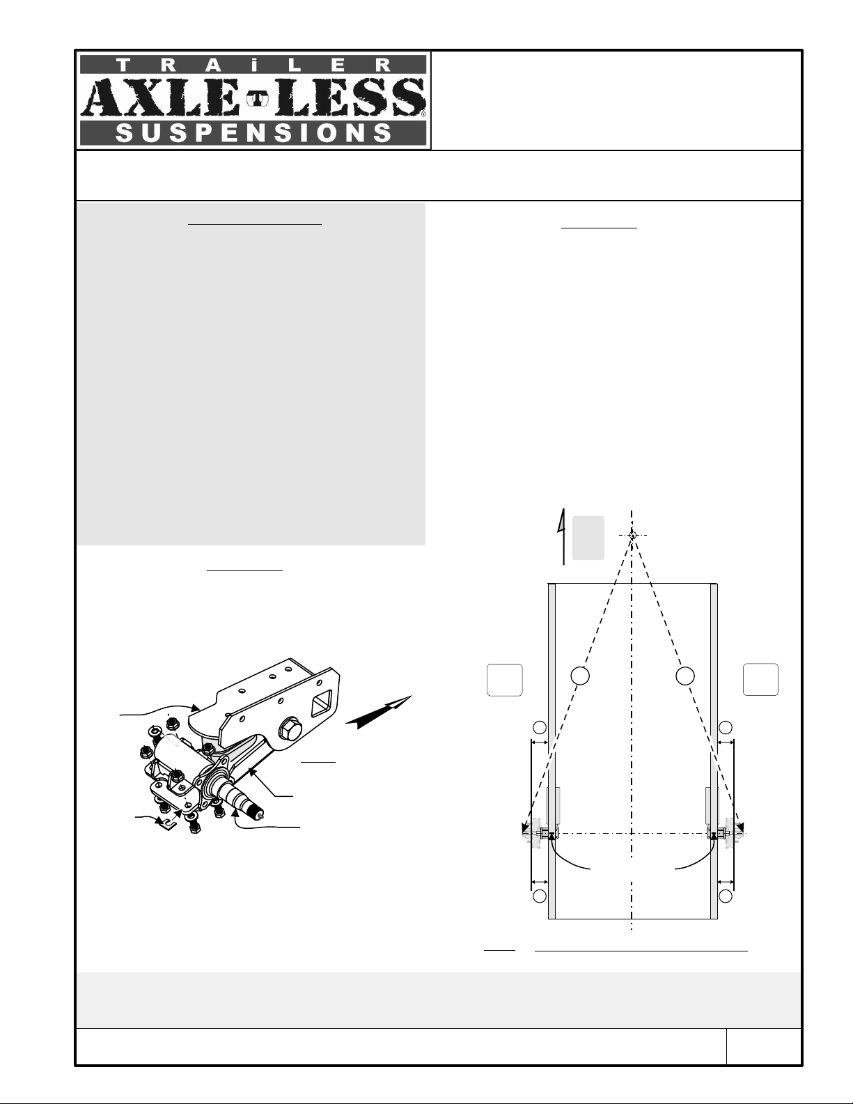
1. Install outboard arm on control arm using 4 bolts and
washers and shims as required (verify that bolts are grade
8). Fig. 1 shows what the right hand side should look like;
the left hand side is the mirror image. Torque fasteners to
90-95 ft-lbs (122-129 N.m). Skip this section if outboard
arm is factory pre-assembled.
(1)
Procedure: (Cont.)
3. Locate the left hand and right hand side hangers on
frame rails, opposite to each other. Move hangers along
frame until center of spindles line up with marks on the frame
rails, viewing from top (fig. 2). Clamp hangers to frame.
Measure and compare distances “A” and “B”. Reposition
hangers until the difference between “A” and “B”
measurements is less than 1/8” (3 mm).
4. Be aware that the suspension has factory toe-in angles
built in. The correct alignment can be obtained ONLY if
frame and its crossmembers or mounting surfaces to the
suspension are perfectly square and they are sufficiently
strong to remain square under maximum loads. Slight
camber adjustments and corrections may be necessary by
using the shims between the outboard arm and control arm
before tightening the 4 bolts.
Hitch
Right hand side
B
Frame Rail
Y=Y
A=B
Front
of
Trailer
Left hand side
Frame Rail
A
Hanger
Alignment
Shim
Fig. 1 :
outboard arm
to control arm
Control Arm
(Right hand side)
Outboard Arm
Front
Assembly of
Y
Hub Face
Y
Centerline of trailer
Hub Face
2. Make sure frame is perfectly square. Measure and
compare the diagonal distances from one corner of
Mark Frame Rails
frame to the opposite corner. Also measure and compare
the distances from the hitch to each rear corner of frame.
Y
Y
Ideally the measurements are identical (in each case the
difference should be less than 1/8” (3 mm).
Mark frame rails where centerline of spindles (wheels)
should cross frame (fig. 2) .
(1) To add rigidity to the trailer frame structure we recommend using rectangular-shape or fabricated box-form steel sections combined with crossmembers of larger
sizes; ultimately it will be the trailer manufacturer's responsibility to make sure that the frame is strong enough to be used with the AxleLess suspension.
(2) Be aware that the driver side and passenger sides have their own factory built-in camber and toe-in angles and therefore the two spindles do not need to be
exactly parallel.
TIMBREN INDUSTRIES INC. - 1-800-263-3113 - sales@timbren.com
(2)
Fig. 2
Spindle Alignment (View from the top)
Page 1
Installation Instructions
Procedure: (Cont.)
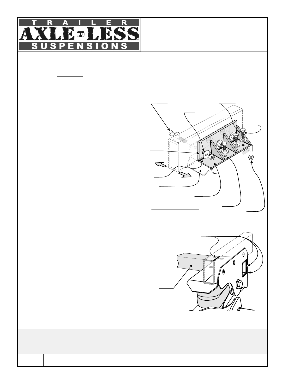
5. Bolt hanger side plate: (fig. 3): Use holes in the hanger
side plate as a template (3 holes). Drill horizontal holes to the
side of frame at each side of trailer. Use ½ ” UNC Gr 8 bolts,
lock-nuts, and washers to mount hangers to frame (fasteners
are not included). Torque mounting bolts to 90-95 ft-lbs (122129 N.m).
6. Do either 6a or 6b (whichever is easier or more practical):
6.a) Bolt hanger top plate to frame : Hanger top plate must
be in full contact with the frame so that it can be bolted to
frame. Use holes in the hanger top plate as a template and
drill vertical holes (note that two ½”nuts are tack welded
inside hanger . In case frame is not wide enough, hanger top
plate can be bolted to crossmembers of frame instead (as
long as those crossmembers are strong enough). If
crossmembers exists but there is a gap between bottom
surface of crossmembers and top of hanger then steel
spacers (plates) should be used to fill up the gap. Drill
common holes to bolt hanger to crossmembers. Use ½ ”
UNC (grade 8) bolts and washers to mount hanger
top plate to frame (fasteners are not included). Make sure
bolts are long enough the entire length of nuts but they are
not too long to interfere with other parts of suspension in the
hanger. If trailer does not have crossmembers (but frame
main beam itself is sufficiently strong to overcome torsion of
frame) then fabricate an inboard extension and attach it to
the frame. Reinforce it by gussets as necessary (fig. 3)
to make it rigid.
(3) (4)
(3)
Typical Installation
Fasteners to mount
Suspension / Hanger
to Frame
(not supplied)
Drill horizontal
holes
Clamp
Clamp
plate
plate
(Not supplied)
(Not supplied)
Outboard
Weld
Inboard
Hanger
Inboard extension plate
(not supplied)
Fig. 3 : Reinforcing frame
Frame Rail
Position gussets and
weld them to clamp plate
Drill
vertical
holes
1/2” UNC
Use
stover
flange
nut here
or a
Locknut
and a
washer.
6.b) Skip procedure (6.a) and install a simple suspension
crossmember if one or more of the following applies:
- You are retrofitting axles / suspensions on a standard
trailer;
- The design of the trailer does not allow drilling vertical
holes for bolting hanger top plate;
- Frame could be aluminum; creating frame inboard
extension may not be practical;
- Frame crossmembers may not be located directly above
hanger top plate and modifying or relocating them is not
optional procedure:
Use a 2"x2"x 1/4” (minimum) structural steel tube
section. Measure width of trailer and saw cut a piece to
that length. Slide tube through corresponding opening in
the driver and passenger-side hangers. Drill two holes at
each end and bolt suspension crossmember to hanger
weld it at each end (fig. 4).
7. Remove clamps.
(3) Welding the hanger is optional (instead of bolting it), but be aware that all paint around welding edges need to be ground off prior to welding. Protect Aeon®
rubber spring from extreme heat generated during welding.
(4) When bolting the frame be aware that hollow (tubular) sections of frame may not be sufficiently strong to withstand compression of bolted joints and therefore
may collapse unless they are reinforced; consider fabricating a bracket similar to the one shown in fig 3 which has a clamp plate to go between the nut/head of bolt
and tube. Such bracket must be rigid enough to allow you to apply a full torque to bolts.
Insert a
suspension
crossmember
(not supplied)
Fig. 4 : Suspension crossmember installed
Weld crossmember
to hanger
Page 2
TIMBREN INDUSTRIES INC. - 1-800-263-3113 - sales@timbren.com
 Loading...