

Page 1

Owner
’s M
anual
ASSE
M
BLY & OP
ERATING
INSTRU
CTIO
NS
MODEL NO. TW-LS-25T
Page 2

To The Owner
Thank You!
Thank you for purchasing our 25T Timberwolf Log Splitter. It was carefully engineered to provide
excellent performance when properly operated and maintained.
Please read this entire manual prior to operating the equipment. It instructs you how to safely and easily set
up, operate and maintain your machine. Please be sure that you, and any other persons who will operate
the machine, carefully follow the recommended safety practices at all times. Failure to do so could result in
personal injury or property damage.
All information in this manual is relative to the most recent product information available at the time of
printing. Review this manual frequently to familiarise yourself with the machine, its features and operation.
Please be aware that this Operator’s Manual may cover a range of product specifications for various models.
Characteristics and features discussed and/or illustrated in this manual may not be applicable to all models.
We reserve the right to change product specifications, designs and equipment without notice and without
incurring obligation.
The power testing information used to establish the power rating of the engine equipped on this machine
can be foundon the engine manufacturer’s manual or website. If you have any problems or questions
concerning the machine, phone an authorized service dealer or contact us directly.
Throughout this manual, all references to right and left side of the machine are observed from the
operating position The engine manufacturer is responsible for all engine-related issues with regards
to performance, power-rating, specifications, warranty and service. Please refer to the engine
manufacturer’s Owner’s/Operator’s Manual, packed separately with your machine, for more
information.
Customer Support
Please do NOT return the machine to the retailer or dealer without first contacting the Customer
Support Department.
If you have difficulty assembling this product or have any questions regarding the controls, operation, or
maintenance of this machine, you can seek help from the experts.
Page 3

Table of C
on
tents
Page(s )
Important Safety Information..................................................................................................................... 1-10
General Safety Alert Signals ....................................................................................................... 1
Safety Decals .............................................................................................................................. 2
Safety Symbols ........................................................................................................................... 3
Training ....................................................................................................................................... 4
Pre-operation .............................................................................................................................. 5
Operation ..................................................................................................................................... 6
Operator Zone.............................................................................................................................. 7
Maintenance Safety..................................................................................................................... 8
Fire Prevention ........................................................................................................................... 9
Towing Safety .............................................................................................................................. 10
Assembly & Set-up Instructions ............................................................................................................... 11-22
Unpacking the Container............................................................................................................. 11-12
Assembling ................................................................................................................................ 13-19
Set-up ......................................................................................................................................... 20-21
Know Controls & Features........................................................................................................... 22
Operating Instructions .............................................................................................................................. 23-26
Starting & Stopping the Engine.................................................................................................... 23
Operating Positions ..................................................................................................................... 23
Using Control Handle................................................................................................................... 24
Splitting the Wood ....................................................................................................................... 25
Transporting the Log Splitter ....................................................................................................... 26
Maintenance & Adjustments..................................................................................................................... 27-28
Troubleshooting........................................................................................................................................ 29
Specifications ........................................................................................................................................... 30
Exploded Diagram & Parts List ................................................................................................................ 31-34
Packing List............................................................................................................................................... 35
Warranty Service Information................................................................................................................... 36
Page 4

WARNING: Read and thoroughly understand all instructions in this manual and on safety decals
before assembling or operating this log splitter. Failure to do so may cause serious injury or death. Do
not allow anyone to operate this log splitter who has not read this manual. As with all power
equipment, a log splitter can be dangerous if assembled or used improperly. Do not operate this log
splitter if you have any questions concerning safe operation. To get answers to any questions, call our
customer service department
.
This SAFETY ALERT SYMBOL identifies important safety messages in this manual.
Failure to follow this important safety information may result in serious injury or death.
DANGER! This machine was built to be operated according to the safe operation practices in this
manual. As with any type of power equipment, carelessness or error on the part of the operator can
result in serious injury. This machine is capable of amputating hands and feet and throwing debris.
Failure to observ e the following safety instructions could result in serious injury or death.
The following signal words and meanings are intended to explain the levels of risk associated with this product.
DANGER indicates a hazardous situation which, if not followed,
will result in serious injury or death.
WARNING indicates a hazardous situation which, if not avoided,
could result in serious injury or death.
CAUTION indicates a hazardous situation which, if not avoided,
could result in minor or moderate injury.
NOTICE is important information about the proper use of
your machine. Failure to follow this instruction could result
in damage to your machine or property.
Page 1
Page 5
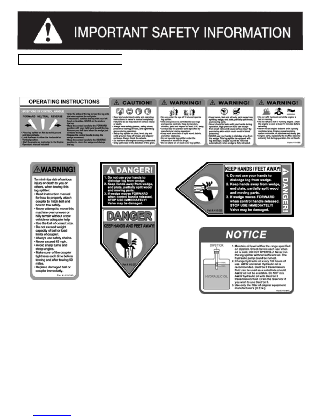
SAFETY dDECsaALS
SAFETY DECALS
Make sure that all safety warning decals are in good condition and readable. Always replace missing or defaced decals.
Contact
us
for replacement decals.
Page 2
Page 6
SAFETY dDECsaALS
SAFETY DECALS
Make sure that all safety warning decals are in good condition and readable. Always replace missing or defaced decals.
Contact
us
for replacement decals.
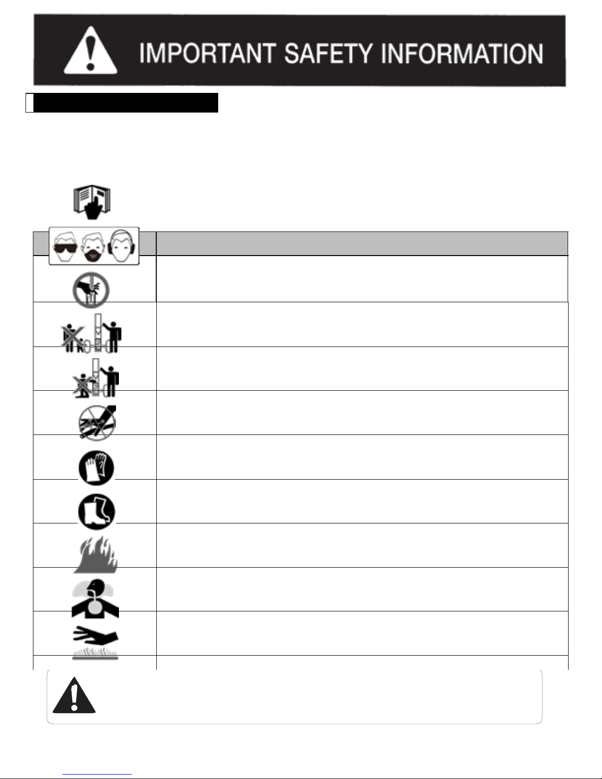
SAFETY SYMBOLS
This page depicts and describes safety symbols that may appear on this product. Read, understand, and follow all
instructions on the machine before attempting to assemble and operate.
Symbol
Description
READ THE OPERATOR’S MANUAL(S)
Read, understand, and follow all instructions in the manual(s) before attempting to
assemble and operate.
FACE PROTECTION
Always wear safety goggles or safety glass es with side shields, or a face shield when
operating this product as well as ear protection.
WARNING— MOVING WEDGE
Keep hands away from wedge, moving part, end plate, and partially split wood.
BYSTANDERS
Keep bystanders, helpers and children at least 10 metre away.
SINGLE OPERATOR
Only one person should operate the machine at a time. The adult who loads and stabilizes
the log must be the person who operates control handle.
WARNING— PRESSURISED FLUID
Never check for hose leaks with your hands. High pressure fluid can escape through a pin
hole leak and cause serious injury by puncturing the skin and causing blood poisoning.
WEAR GLOVES
Always wear nonslip, heavy-duty protective gloves when operating this product.
WEAR SAFETY FOOTWEAR
Always wear nonslip steel-toed safety footwear when operating this product.
WARNING—PETROL IS FLAMMABLE
Allow the engine to cool at least ten minutes before refuelling.
WARNING! Your Responsibility—Restrict the use of this power machine to persons who read,
understand and follow the warnings and instructions in this manual and on the machine.
SAVE THESE INSTRUCTIO NS!
Page 3
Page 7

TRAINING
1. Read, understand, and follow all instructions on the machine and in the manual(s) before attempting to assemble and
operate. Keep this manual in a safe place for future and regular reference and for ordering replacement parts.
2. Be familiar with all controls and their proper operation. Know how to stop the machine and disengage them quickly.
3. Never allow children under 18 years of age to operate this machine. Children 16 and over should read and
understand the instructions and safe operation practices in this manual and on the machine and be trained and
supervised by an adult.
4. Never allow adults to operate this machine without proper instruction.
5. Many accidents occur when more than one person operates the machine. No helper is allowed to assist in stacking
logs.
6. Keep bystanders, pets, and children at least 10 metre from the machine while it is in operation.
7. Never allow anyone to ride on this machine.
8. Never transport cargo on this machine.
9. Hydraulic log splitters develop high fluid pressures during operation. Fluid escaping through a pin hole opening can
penetrate your skin and cause blood poisoning, gangrene, or death. Give attention to the following instructions at all
times:
a. Do not check for leaks with your hand.
b. Do not operate machine with frayed, kinked, cracked, or damaged hoses, fittings, or tubing.
c. Stop the engine and relieve hydraulic system pressure by cycling the valve control lever from forward to reverse
several times while engine is not running. Return to neutral before repairing or adjusting fittings, hoses, tubing, or
other system components.
d. Do not adjust the pressure settings of the pump or valve.
10. Leaks can be detected by passing cardboard or wood over the suspected areas. Always wear protective gloves and
safety glasses when checking. Look for discoloration of cardboard or wood.
11. If injured by escaping fluid, see a doctor immediately. Serious infection or reaction can develop if proper medical
treatment is not administered immediately.
12. Keep the operator zone and adjacent area clear for safe, secure footing.
13. If your machine is equipped with an internal combustion engine and is intended for use near any unimproved forest,
brush, or grass covered land, the engine exhaust should be equipped with a spark arrestor. Make sure you comply
with applicable local, state, and federal codes. Take appropriate firefighting equipment with you.
NEVER use this log splitter for any purpose other than
splitting wood. It is designed for this use only. Any other
use can cause serious injury or death.
Page 4
Page 8

PRE-OPE RATION
1. BEFORE operating this log splitter, make sure that you wear safety gear such as goggles or safety glasses,
steel toed shoes and tight fitting gloves (without loose cuffs or draw strings). Always wear a protective hearing
device when operating this log splitter.
2. NEVER wear loose clothing or jewelry that can be caught by moving parts of the log splitter. Keep clothing and
hair away from all moving parts when operating this log splitter.
3. Check all safety guards and shields to be sure they are in the proper position. Never operate with safety guards,
shields, or other protective features removed.
4. Make sure machine is on a flat, dry, solid ground before operating.
5. ALWAYS operate your log splitter in an open area. (Exhaust fumes contain carbon monoxide which can be
deadly when inhaled.)
6. ALWAYS operate your log splitter in daylight or under good artificial light.
7. ALWAYS operate your log splitter on level ground. (Operating on a slope could cause the log splitter to roll over or
logs to fall off.)
8. ALWAYS block wheels to prevent unintended movement.
9. ALWAYS lock beam in either the horizontal or vertical position.
10.
ALWAYS keep the work area clean. Remove split wood from around the log splitter immediately so that you
don’t stumble over it.
11. Check all nuts, bolts and hydraulic fittings are tight to be sure the equipment is in a safe working condition.
12. Both ends of the log should be cut as square as possible to help prevent the log from riding out of the splitter
during operation. Do not split logs greater than 510mm in length. Uneven logs (e.g. knotted, curved, etc.)
should not be used.
13.
ALWAYS check the oil level before you start the log splitter. See Page 27
.
14. Do not allow familiarity with tools to make you careless. Remember that a careless fraction of a second is
sufficient to inflict serious injury.
W
ARNING:
The operation of any power tool can result in foreign objects being thrown into your eyes, which
can result in severe eye damage. Before beginning power tool operation, always wear safety goggles or
safety
glasses with side shields and, when needed, wear a full face shield and earplugs too. We
recommend a Wide Vision Safety Mask for use over eyeglasses or standard safety glasses with side
shields. Always use eye protection which is marked to comply with ANSIZ87.1.
D USE
Page 5
Page 9

OPERATION
1. BEFORE starting this machine, review the safety instructions in the manual. Failure to follow these rules may result
in serious injury to the operator or bystanders.
2. NEVER leave this machine unattended with the engine running.
3. DO NOT operate machine while under the influence of alcohol, drugs, or medication.
4. NEVER allow anyone to operate this machine without proper instruction.
5. ALWAYS operate this machine with all safety equipment in place and working. Make sure all controls are operating
properly for safe operation.
6. When loading a log, always place your hands on the side of the log, not on the ends, and never use your foot to help
stabilize a log. Failure to do so may result in crushed or amputated fingers, toes, hand, or foot.
7. NEVER use your foot, a rope or any extension device to operate the control lever on the valve. Only use hand.
8. Use only one hand to operate the controls.
WARNING! When stabilizing log with other hand, remove your hand when the wedge begins to contact the log, or
serious injury may occur.
9. For logs which are not cut square, the least square end of the log should be placed toward the beam and wedge, and
the square end placed toward the end plate.
10. When splitting in the vertical position, stabilize the log before moving the control handle. Split as follows:
a. Place log on the end plate and turn until it leans against the beam and is stable.
b. When splitting extra-large or uneven logs, the log must be stabilized with wooden shims or split wood placed
between the log and end plate or ground.
11. NEVER place hands or feet between the log and splitting wedge during forward or reverse stroke as this could result in
serious injury or death. NEVER attempt to load the log splitter when the ram or wedge is in motion.
12. ALWAYS keep fingers away from any cracks that open in the log while splitting. They can quickly close and pinch or
amputate your fingers.
13. Keep your work area clean. Immediately remove split wood from around the machine so you do not stumble over it.
14. NEVER straddle or step over the log splitter during operation.
15. NEVER reach or bend over the log splitter to pick up a log.
16. NEVER try to split two logs on top of each other. NEVER try to cross split a log.
17. NEVER operate your log splitter when it is in poor mechanical condition or in need of repair.
18. NEVER touch the muffler and other hot areas of the engine during operation. Wait until the engine cools down.
19. NEVER tamper with the engine to run it at excessive speeds. The maximum engine speed is pre-set by the
manufacturer and is within safety limits. Refer to the engine owner’s manual for your particular log splitter.
20. NEVER move the log splitter while the engine is running. Shut off the engine if you are leaving the log splitter, even for
a short period of time.
21. ALWAYS be careful when moving or lifting the log splitter. Get assistance if it feels too heavy to move by yourself.
Page 6
Page 10
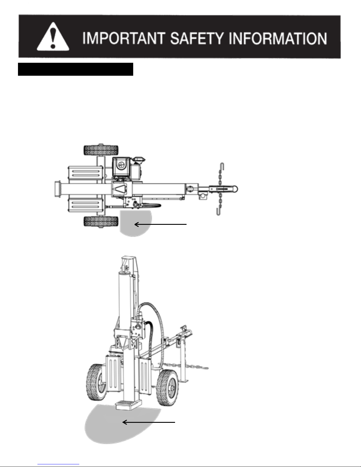
OPERATOR ZONE
ONLY operate the log splitter from the operator zone as shown in the diagrams below. The operator has the safest and
most efficient access to the control valve and the beam in this location. Operating the log splitter in another location can
result in serious injury or death.
a. Horizontal Operating Position: Stand on the control lever side of the log splitter and stabilize log if needed. See
FIGURE 1.
(FIGURE 1).
Operator Zone
b. Vertical Operating Position: Stand in front of the log splitter and stabilize log if needed. See FIGURE 2.
(FIGURE 2).
GENERAL REPAIR
Operator Zone
Page 7
Page 11

MAINTENANCE SAFETY
1. Stop the engine, disconnect the spark plug and ground it against the engine before cleaning, or inspecting the machine.
NEVER perform any service or repair on your log splitter without first removing the spark plug wire.
2. Stop the engine and relieve hydraulic system pressure by cycling the valve control lever from forward to reverse several
times while engine is not running. Return it to neutral before repairing or adjusting fittings, hoses, tubing, or other system
components.
3. ALWAYS perform all recommended maintenance procedures before using your log splitter.
4. ALWAYS check the level of hydraulic oil and engine oil before operation.
5. ALWAYS periodically check that all nuts, bolts, screws, hydraulic fittings and hose clamps are tight to be sure equipment is
in safe working condition.
6. ALWAYS replace all damaged or worn parts immediately with original equipment manufacturer’s (O.E.M.) parts only.
Use of parts which do not meet the original equipment specifications may lead to improper performance and
compromise safety.
7. The hydraulic system of your log splitter requires careful inspection along with the mechanical parts. Be sure to replace
frayed, kinked, cracked or otherwise damaged hydraulic hoses or hydraulic components.
8. NEVER check for leaks of hydraulic fluid with your hand. Fluid escaping from a small hole can be almost invisible.
Escaping fluid under pressure can have sufficient force to penetrate skin causing SERIOUS INJURY or even
DEATH. Leaks can be safely detected by passing a piece of cardboard over the suspected area and looking for
discoloration.
9. NEVER remove the cap from the hydraulic tank or reservoir while the log splitter is running. The tank could contain
hot oil under pressure which could result in serious injury.
10. NEVER adjust the hydraulic valve. The pressure relief valve on your log splitter is pre-set at the factory. Only a qualified
service technician should perform this adjustment.
11. ALWAYS seek professional medical attention immediately if injured by escaping hydraulic fluid. Serious infection or
reaction can develop if proper medical treatment is not administered immediately.
12. ALWAYS be sure to relieve all pressure by shutting off the engine and moving the valve control handle back and forth
should it become necessary to loosen or remove any hydraulic fitting.
NEVER alter your log splitter in any manner. Such alterations may cause your log
splitter to be unsafe and will void the warranty.
Page 8
Page 12

FIRE PREVENTION
VENTION
1. ALWAYS take a Class B fire extinguisher with you when operating this log splitter in dry areas.
2. NEVER operate your log splitter near a flame or spark or smoke during operation. Extinguish all cigarettes, cigars,
pipes, and other sources of ignition. Hydraulic oil and petrol are flammable and can explode.
3.
To avoid personal injury or property damage use extreme care in handling petrol. Petrol is extremely flammable and the
vapours are explosive.
4. ALWAYS store petrol in an approved, tightly sealed container and keep away from heating appliances. Store the
container in a cool, dry place.
5. When petrol is spilled on yourself or your clothes, wash your skin and change clothes immediately.
6. NEVER refuel the fuel tank while the engine is hot or running. Allow the engine to cool before refuelling.
7. ONLY refuel your log splitter in a clear area with no gas fumes or spilled gas. Never fuel the machine indoors.
8. Never overfill the fuel tank. Fill tank to no more than15mm below bottom of filler neck to provide space for fuel
expansion.
9. If petrol is spilled out, wipe it off the engine and equipment, and move machine to another area. Wait five (5)
minutes before starting the engine.
10. ALWAYS replace the fuel cap securely. Never remove fuel cap while the engine is hot or running.
11. To prevent fires, clean debris and chaff from the engine and muffler areas.
12. Allow machine to cool at least ten (10) minutes before storing.
13. ALWAYS drain the fuel tank prior to storage to avoid the potential fire hazard.
14. Never store the machine or fuel container inside where there is an open flame, spark or pilot light as on a water heater,
space heater, furnace, clothes dryer or other gas appliances.
15. If the engine is equipped with a spark arrestor muffler, clean and inspect it regularly according to manufacturer’s
instructions. Replace if damaged.
Page 9
Page 13

TOWING SAFETY
1. NEVER carry any cargo or wood on your log splitter.
2. NEVER allow anyone to sit or ride on your log splitter.
3. ALWAYS turn the fuel shut off valve on the engine to the “OFF” position before towing the log splitter. Failure to do so
may result in flooding the engine.
4. ALWAYS check to make sure the low coupler is adjusted properly each time before towing and after towing 80 km.
5. ALWAYS check before towing to make sure that the log splitter is correctly and securely attached to the towing vehicle
and that the safety chains are secured to the hitch or bumper of the vehicle with enough slack to allow turning. Always
use a Class I,
2”
ball with this log splitter.
6. NEVER exceed weight capacity of ball or load limits of coupler. ALWAYS replace ball or coupler if damaged.
7. NEVER exceed 60 km/h when towing your log splitter. Towing the log splitter at speeds higher than 60 km/h
could result in loss of control, damage to the equipment, or serious injury or death. Adjust towing speed for terrain
and conditions.
8. ALWAYS be careful when backing up with your log splitter in tow. It could jack knife.
9. ALWAYS allow for added length of your log splitter when turning, parking and crossing intersections and in all
driving situations.
10. ALWAYS use safety chains when towing your log splitter.
11. Be extra cautious when towing over rough terrain, especially railroad crossings, and avoid sharp turns and steep
angles when towing your log splitter.
12. Never attempt to move this machine over hilly or uneven terrain without a tow vehicle or adequate help.
13. ALWAYS disconnect your log splitter from the towing vehicle before operating it.
14. ALWAYS check all local and state regulations regarding towing, licensing and lights before towing your log splitter.
This machine should not be towed on any street, highway or public road without checking the existing federal,
state, or local vehicle requirements. Any licensing or modifications such as taillights, etc., needed to comply, is the sole
responsibility of the purchaser. If a “Statement of Origin” is required in your state, see your local dealer.
15. See Transporting the Log Splitter section (Page 26) in this manual for proper towing instructions once all federal, local, or
state requirements are met.
SAVE THESE INST
RUC
TIONS
Page 10
Page 14

ASSEMBLY & SET-UP INSTRUCTIONS
UNPACKING THE CONTAINER
WARNING! Use extreme caution unpacking this machine. Some components are very heavy and will require
additional people or mechanical handling equipment.
NOTE: All references in this manual to the left or right side and front or back of the log splitter are from the operating
position only. Exceptions, if any, will be specified.
Unpacking tools needed:
1. Wrench 13mm
2. Scissors or knife
3. Pry bar or claw hammer
Step 1: Use a 13mm wrench to remove the bottom bolts and washers securing the crate side frames onto the crate
bottom, and then lift up and put away the crate top with the cardboard box together. See FIGURE 3.
Crate Top
(FIGURE 3)
Crate Side
Frame
Flat Washer x 24PCS
Crate Bottom
Hex head bolt x 24PCS
Page 11
Page 15

Step 2: Remove all loose parts included in the container, e.g. wheels and hardware box.
Step 3: Use scissors or a knife to cut and remove the straps securing the parts to the beam or tank assembl y, including
tongue assembly and log tray assemblies, and put aside these parts for assembly.
NOTE: DO NOT remove the strap securing the hydraulic hoses assemblies to the beam at this time, until you do the
assembly procedure of the hoses.
Step 4: Use scissors or a knife to cut and remove the straps securing the engine / pump assembly to the crate bottom,
and then place aside carefully for assembly.
Step 5: Use a pry bar or claw hammer to remove the plywood splinters securing the beam and tank assembli es on the
crate bottom. Take out the two heavy assemblies.
NOTE: Due to the weight / size of the two assemblies, it’s recommended two or more adults to assist lifting and moving
the two assemblies. Lifting tools as hoist, crane, jack, etc. are recommended too.
Step 6: Inspect all component assemblies, parts and accessories according to the packing list attached in this manual
(Page 35). Make sure all items listed in the packing list are included and of no shipping damage.
If any parts are damaged or missing, please call our customer service department for assistance.
NOTE: DO NOT discard the packing materials until you have carefully inspected and satisfactorily operated the tool.
Page 12
Page 16

ASSEMBLY & SET-UP INSTRUCTIONS
ASSEMBLING
NOTE: Due to the weight / size of the log splitter, it’s recommended that two or more adults be present to assist with the
assembling. Some lifting tools such as hoist, crane, jack, etc. are recommended too.
Assembling tools needed:
1. Wrench 13mm x 2
2. Wrench 14mm x 2
3. Wrench 16, 17, 18, 19, 27, 32 mm one each
4. Wrench 1 / 2
” x
1
5. Adjustable wrench x 1
6. Needle nose pliers x 1
7. Allen wrench 3mm x 1
8. Flat head screwdriver x 1
9. Soft faced hammer x 1
10. Thread locking compound x 1
STEP 1: Install the tongue assembly to the reservoir tank. See FIGURE 4.
1. Pull out the spring loaded lock handle of flip-down stand which hold the stand on the tongue, and then the stand will
automatically flip down towards the ground and be secured in position.
2. Remove the M10 hardware from the beam support bracket on the tank using a 16mm wrench for bolts and a 17mm
wrench for the lock nuts. Attach the tongue to the reservoir assembly and screw on the hardware just removed and
tighten.
(FIGURE 4)
Stand Lock
Flip-down Stand
REF. NO.
1
2
DECSRIPTION
QTY.
Reservoir tank assembly 1
Tongue & Flip-down stand assembly 1
3 M10 Hardware on beam support bracket, including: 1
3-1 Hex head bolt / M10 x 75 2
3-2 Flat washer / M10 4
3-3 Lock nut / M10 2
Page 13
Page 17

STEP 2: Install the two wheels. See FIGURE 5.
1. Raise the reservoir tank assembly off the ground on some blocks before mounting. Remove the plastic shipping
caps from the wheels and position the wheels onto the wheel axels.
2. Screw the castle nuts onto the axels and tighten with an adjustable wrench to seat the bearings. Then back the
castle nuts off one half turn and snug them up to the bearings by hand, so they line up with the hole in the axel.
3. Insert the split pin into the slot of castle nut and the hole in the axel, then bend the ends of the pin with needle nose
pliers keeping it close to the castle nut so the dust cap fits over it.
4. Tap the dust caps onto the wheel using a soft faced hammer.
(FIGURE 5)
REF. NO.
4
5
5-1
5-2
5-3
DECSRIPTION
QTY.
Off – Road tyre / Wheel 2
Hardware Kit #2, including: 1
Castle nut / 1-14 2
Split pin / Ø4 x
50 2
Dust cap 2
Page 14
Page 18

STEP 3: Install the engine / pump assembly to the engine mount plate on the reservoir assembly. See FIGURE 6.
1. Insert a vibration isolator between the engine and the mount plate at each of the four mounting hole positions.
2. Secure the engine with the hardware, then tighten the hardware using two 13mm wrenches for 25 ton model;
or 16mm wrench on bolts, 17mm wrench on lock nuts for 30 / 35 ton model.
(FIGURE 6)
REF. NO.
9
10
10-1
10-2
10-3
10-4
//
DECSRIPTION
Engine / Pump assembly
Hardware kit # 5-1 (25 / 30T)
Hex head bolt / M8 x 40 (25 / 30T)
Flat washer / M8 (25 / 30T)
Lock nut / M8 (25 / 30T) Vibration
isolator / Ø9 (25 / 30T)
O Seal ring /
Ø15*1.9
QTY.
1
or # 5-2 (35T), including: 1
or M10 x 40 (35T)
4
or M10 (35T)
8
or M10 (35T)
4
or Ø11 (35T)
4
2
NOTE: In the Hardware Kit # 5-1 or 5-2, you have one O seal ring /
Ø15*1.9, which i
s
a spare O ring to be used in
the
“STEP 6:
Connect hydraulic hoses” section if you can’t find one sitting in the fitting slot on the
reservoir tank, when you attach the oil return hose
③
to the reservoir tank.
Page 15
Page 19

STEP 4: Install the beam assembly. See FIGURE 7.
1. Stand the beam upright on a flat level. Two or more people are recommended to assist with raising and lowering the
beam as it is very heavy. Have a helper support the beam as you perform the following steps. Be sure to keep hands
away from any possible pinch points.
2. Remove the clevis pin and spring clip from the beam support bracket on the tank. Position the tongue / tank
assembly so that the beam support bracket is in between the two tabs on the beam.
3. Slide the clevis pin through the aligned holes and secure with the spring clip. You may need another helper to lift up
the tongue for the holes to align.
4. Leave the beam in the vertical position for continual assembling steps.
(FIGURE 7)
REF. NO.
11
DECSRIPTION
QTY.
Beam assembly 1
WARNING! Take extra care when raising and lowerin g the beam as it is fairly heavy. Having a
second person assist with raising or lowering the beam is recommended. Be sure to keep hands
away from any possible pinch points.
Page 16
Page 20

STEP 5: Connect hydraulic hoses. See FIGURE 8.
There are three hydraulic hoses listed below, each of them has one end fixed on the log splitter by manufacturer, and the
other open end still needs to be attached. The hoses are labelled on the ends for easy installation.
1. Oil suction hose 3/4”, labelled as
①, comes from the bottom of the reservoir (Note: some items may have this hose in
the hardware kit box).
Loosen the hose clamp on the open end of this hose using a flat head screwdriver, and then connect the hose to the
fitting on the bottom of the pump, which is also labelled as
①. Tighten the hose clamp.
2. Pump / Valve connecting hose ½”, labelled as
②, comes from the bottom of the valve on the beam assembly.
Screw the open end of this hose onto the fitting on top of the pump, which is also labelled as
②.
Tighten using a
27mm wrench or an adjustable wrench.
3. Oil return hose 1/2”, labelled as
③, comes from the top of the valve on the beam assembly.
Screw the open end of this hose onto the fitting on the reservoir tank, which is also labelled
as③. Make sure an O-
ring
Ø
15*1.9 sitting inside the fitting slot. Or you could find a spare O-ring in your hardware kit # 5-1 or 5-2 (See page 15).
Tighten the hose using a 32mm wrench or an adjustable wrench.
(FIGURE 8)
.
Valve
Hose
Clamp
Pump
Page 17
Page 21

STEP 6: Install the log tray assemblies. See FIGURE 9.
1. Lower the beam to horizontal position. Please refer to “Beam Operating Positions” section in Page 23.
2. Position the log tray frames onto the beam as shown below and secures with the M10 hardware loosely.
3. Tighten the M10 hardware using a 16mm wrench on the bolts, and a 17mm wrench on the lock nuts
(FIGURE 9)
REF. NO.
12
13
13-1
13-2
13-3
DECSRIPTION
QTY.
Log tray assembly 2
Hardware Kit # 6-1, including: 1
Hex head bolt / M10 x 45 4
Flat washer / M10 8
Lock nut / M10 4
Page 18
Page 22

STEP 7: Assemble the control handle. See FIGURE 10.
The control handle is shipped hanging from the valve on the handle link.
1. Remove the clevis pin and bow-tie cotter pin from the valve.
2. Rotate the control handle up into the operating position and secure with the clevis pin and cotter pin just remov ed.
(FIGURE10)
Page 19
Page 23

ASSEMBLY & SET-UP INSTRUCTIONS
Fuel and
Oil Fill-Up
Service the engine with petrol and engine oil as instructed in the engine manual packed with your log splitter. Read the
instructions carefully.
WARNING! Use extreme care when handling petrol. Petrol is extremely flammable and the vapours are
explosive. Never fuel the machine indoors or while the engine is hot or running.
NOTE: Your log splitter may be shipped without engine oil. You MUST check the oil level before operating. Be careful
not to overfill. Petrol should be added to the engine when the log splitter is in either the horizontal or vertical position.
However, it may be easier when the splitter is in the vertical position.
A
djust Handle Rel
ease L
ever
Your log splitter is equipped with an external
pressure release system which is attached
under the valve bracket. When you set up the
machine and try it, you will see the back of the
wedge hits the handle release lever when the
wedge is fully retracted. The control handle is
then kicked back from reverse position to the
neutral position automatically.
The lever may need to be adjusted if the wedge
is fully retracted and the control lever does not
automatically kick into the neutral position.
To adjust the handle release lever, See
FIGURE 11
1. Loosen the Jam nut using a 14mm wrench.
2. Screw the adjusting nut counter clockwise
to allow it contact with the wedge as soon as
the wedge is fully retracted.
3. Tighten the jam nut after adjusting.
(FIGURE11)
Jam Nut
Adjusting
Bolt
Wedge
Handle
Release
Lever
Valve
Bracket
Control
Handle
Lubri
cate the Beam
Lubricate the beam area (where the splitting
wedge will slide) with engine oil. Do not use
(FIGURE12)
grease. See FIGURE 12.
Page 20
Page 24

SAFETY dDECsaALS
SAFETY DECALS
Make sure that all safety warning decals are in good condition and readable. Always replace missing or defaced decals.
Fill hydraulic
oil
The log splitter is shipped without hydraulic fluid in the reservoir. Fill the reservoir before your initial use.
1. Remove the vented reservoir dipstick, which is located next to the engine on top of the reservoir tank.
See FIGURE 13.
Please select the oil based on the outside
temperature range the log splitter will be used in.
Refer to the chart provided to select the appropriate
hydraulic oil.
ISO 32
0° 10°
20° 30° 40° 50° 60°
70°
80°
90°
(-18°) (-12°) (-7°) (-1°) (4°) (10°) (16°) (21°) (27°) (32°)
Approved fluids include Shell Tellus® S2 M 32
Hydraulic Fluid, Dexron® III / Mercon® automatic
transmission fluid, Pro-Select™ AW-32 Hydraulic Oil
or 10WAW-ISO viscosity grade 32 hydraulic oil. It is
not recommended that fluids be mixed, to top off the
reservoir tank during initial set-up use Shell Tellus®
S2 M 32 Hydraulic Fluid only.
2. Slowly fill the reservoir with the recommended hydraulic oil until oil level reaches the maximum line on the dipstick.
3. Replace the vented dipstick in the reservoir.
4. Start the engine, and use the control handle to engage the wedge to the farthest extended position and then retract.
Repeat this operation for 12 cycles. Much of the fluid will be drawn into the cylinder and hoses. Stop the engine, and
check the oil level as instructed below.
NOTE: Make sure the oil level is above the bottom line on the dipstick. If not, refill the reservoir to prevent damage to
the hydraulic pump. DO NOT overfill. Some fluid may overflow from the vent plug as the system builds heat and the
fluid expands and seeks a balanced level.
5. However, you MUST check the fluid level before each operating. If not filled, proceed with above steps.
Page 21
Page 25

K
now Controls and Features
Cylinder
Control Handle
Splitting Wedge
Tongue
Log Dislodger
Log Tray
Flip-down
Stand
End Plate
Horizontal
Beam Lock
(FIGURE14)
NOTE: This Operator’s Manual covers several models. Log splitter features may vary by model. Not all features in this
manual are applicable to all log splitter models and the log splitter depicted may differ from yours.
Beam Lock
The horizontal beam lock, as its name suggests, is used
to secure the beam in the horizontal position. The
horizontal beam lock is located on the beam support latch
bracket.
Engine Controls
See the Engine Operator’s Manual for the location and
function of the controls on the engine.
Control Handle
The control handle has three positions; Forward, Neutral
and Reverse. See the Operation section for instructions
Splitting Wedge
The wedge is used to split the wood.
Log Dislodger
The log dislodgers are designed to remove any
partially split wood from the wedge. This may occur
while splitting large diameter wood or freshly cut
wood.
Log Tray
The log trays are designed to catch the log after it is
split.
Tongue
The tongue is used to attach to a towing vehicle for
transportation.
End Plate
The end plate holds the log in place while the wedge
splits the log.
Page 22
Page 26

SAFETY dDECsaALS
SAFETY DECALS
Make sure that all safety warning decals are in good condition and readable. Always replace missing or defaced decals.
OPERATION INSTRUCTIONS
STARTING & STOPPING THE ENGINE
Refer to the Engine Operator’s manual packed with your log splitter for instructions on starting and stopping the engine.
1. Place the log splitter on flat, dry, solid ground.
2. Block both wheels to prevent your log splitter from moving
during operation. See FIGURE 15.
3. Place the beam in either the horizontal or vertic al position
and lock into place.
WARNING! Take extra care when raising and
lowering the beam as it is fairly heavy. Having a
second person assist with raising or lowering
the beam is recommended.
4. To place the beam in the Vertical Position proceeds as
follows:
1) Pull the horizontal beam lock lever out and rotate it
downward, so it rests against the side of the lock and
remains unlocked. See FIGURE 16.
(FIGURE 16)
2) Use both your hands to lift up the beam, and flip it over
to the vertical position, then rotate the horizontal
lock lever back up the tongue to release the lock.
Beam
5. To place the beam in the Horizontal Position proceeds
as follows:
1) Pivot the beam to the horizontal position.
2) The horizontal beam lock is self-locking. The spring
loaded lock will snap into place when the beam is
lowered into position.
Tongue
Page 23
Page 27

OPERATION INSTRUCTIONS
The control handle has three positions. See FIGURE 17.
(FIGURE 17)
•
FORWARD
— To
split wood. Move the control handle to the FORWARD position to move wedge toward the log to split.
NOTE: The control handle will return to the NEUTRAL position as soon as the handle is released during FORWARD process,
and the wedge stops moving forward. DO NOT hold the handle at the FORWARD position when the wedge is fully extended.
The over built up pressure may squeeze the pressure relief valve, and the control handle won’t be released to NEUTRAL
position automatically. Manuall y pull the handle to NEUTRAL or REVERSE position to recover. Or the hydraulic system may
get damaged and void your warranty.
•
NEUTRAL
— To
stop wedge. Release the control handle or move the lever to the NEUTRAL position to stop the wedge
movement.
•
REVERSE
— To
return the wedge. Engage the control handle to the REVERSE position, the wedge will automatically return
toward the cylinder. When the wedge is fully retracted and contacts the handle release lever, the control handle will return to
the NEUTRAL position automatically.
NOTE: Do not hold the handle in the REVERSE position. It will stay in REVERSE position during the wedge being retracted.
When the wedge is fully retracted, the handle will kick back to the NEUTRAL positon automatically.
WARNING! If the control handle on your log splitter is not functioning properly, STOP USE IMMEDIATELY
and contact an authorized service dealer.
WARNING! Do not attempt to service, repair or replace control valve. Contact an authorized service dealer.
WARNING! Do not attempt to adjust or modify the control valve or the hydraulic system from its original
settings or manufacturer in any way.
Page 24
Page 28

OPERATION INSTRUCTIONS
1. Start the engine as instructed in the Engine Operator’s manual included with the log splitter.
2. Grasp the log on the sides and place it on top of the beam against the end plate. Always split the wood in the direction of
the grain. See FIGURE 18.
3. To stabilize the log, place your left hand on the side of the log. See FIGURE 18.
WARNING! Never place your hand on the ends of the log, between the log and the end plate or the log
and the splitting wedge.
WARNING! Only one operator permitted. The adult who loads and stabil izes the log, must be the
person who operates the control handle.
4. Use your
right
hand to push the control handle lever to the forward position to split the wood.
5. Remove
left
hand from the log once the wedge begins to contact with the log. Continue holding the control handle in
the forward position until the log splits.
6. Release the control handle to stop the wedge movement at any point in the splitting process if you feel an unsafe splitting
condition is occurring. NEVER reach forward and attempt to catch a falling piece of wood---let it fall.
7. Once the log is split or the wedge is fully extended, move the control handle to the reverse position to return the wedge.
DO NOT hold the handle at Forward position as soon as the wedge is fully extended. Or the hydraulic system will get
damaged, and void your warranty.
Right Hand
Left Hand
(FIGURE18)
8. Remove partially split wood from wedge.
1) Move the control handle to the REVERSE position until the wedge is fully retracted to allow the partially split wood to
contact the log dislodgers.
WARNING! Never remove partially split wood from the wedge with your hands. Fingers may become
trapped between the split wood.
2) Once removed from the wedge, split the wood from the opposite end or in another location.
Page 25
Page 29

OPERATION INSTRUCTIONS
TRANSPORTING THE LOG SPLITTER
1. Lower the beam to its horizontal position. Make certain the beam is locked securely with the horizontal beam lock.
2. Pivot the flip-down stand up to transporting position.
1) Pull out the lock handle of the stand and rotate it up. The stand will be secured horizontally with the tongue
automatically. Please refer to FIGURE 5 on page 14.
2) Have a helper to support the tongue, or use a wheeled trailer jack to raise the tongue (optional accessory from the
Manufacturer).
Spring Clip
Locking Pin
Latch Assembly
Hitch Coupler
(FIGURE19)
Safety Chain
3. Pull the latch on the hitch coupler up, position the coupler over onto to the tow ball behind your towing vehicle,
and then close the latch to lock the ball securely. See FIGURE 19
1) If the coupler hitch is too tight and does not fit onto the ball, turn the adjustment nut one turn counter-clockwise.
2) If the coupler hitch is too loose on the ball, turn the adjustment nut one turn clockwise, then recheck and adjust
accordingly.
4. Attach the safety chains to the towing vehicle crossing each other under the tow ball, ensuring there is enough slack for
turning.
5. Insert the locking pin into the hole in the latch assembly and lock with the sprig clip.
WARNING! Do not tow faster than 70km/h and check the local, state and federal requirements before
towing on any public road.
NOTE: Use caution when backing up. Using a spotter outside the vehicle is recommended.
Page 26
Page 30

MAINTENANCE & ADJUSTMENTS
Regular maintenance is the way to ensure the best performance and long life of your machine. Please refer to this manual
and the engine manufacturer’s owner’s manual for maintenance procedures.
WARNING! Do not make any adjustments without first stopping the engine, disconnecting the spark
plug wire and grounding it against the engine. Always wear safety glasses during operation or while
performing any adjustments or repairs.
Engine
Refer to the Engine Operator’s manual packed in the hardware kit box of your log splitter for all engine maintenance
e.g. how to check and change the engine oil.
NOTE: When draining oil from the engine on this log splitter, shield the hoses from any oil that may run down the frame
and drip onto the hoses. Thoroughly wipe any residual oil off the log splitter and hoses after completing service.
Tyre Pressure
The tyres are off-road tyres. The max recommended operating pressure is 30 psi. Do not, under any circumstances, exceed
the manufacturer’s recommended psi. Maintain equal pressure on both tyres.
WARNING! Excessive pressure when seating beads may cause the tyre/rim assembly to burst with
force sufficient to cause serious injury.
Flexible Pump Coupler
The flexible pump coupler, located between the pump and the engine shaft, has a nylon “spider” insert. Over time, the insert will
harden and deteriorate. If you detect vibration or noise coming from the area between the engine and the pump, contact an
authorized deale. Make sure to change a new coupler spider immediately when the coupler spider fails completely, or you will
experience a loss of hydraulic power.
Hydra
ulic
Fluid
Check the hydraulic fluid level in the log splitter reservoir tank before each use. Maintain the fluid level within the range
specified on the dipstick at all times.
Change the hydraulic fluid in the reservoir every 100 hours of operation. Follow the steps below:
1. Place a suitable oil collection container under the tank.
2. Disconnect the oil drain plug from the bottom of the reservoir tank. See FIGURE 20.
4. Allow the fluid to drain into the container.
NOTE: The reservoir tank has a capacity of 15 litres of hydraulic fluid for 25 ton.
splitter. While you may need more hydraulic fluid than the tank capacity, because a lot of oil will stay in hydraulic
cylinder, valve, pump and hoses.
5. After draining, put the oil drain plug back in and tighten.
Page 27
Page 31

(FIGURE20)
(FIGURE21)
6. Refill the reservoir tank (Please follow the steps in Page 21 to fill the tank, and repel the air in the tank).
7. Maintain the fluid level within the range specified on the dipstick at all times. See FIGURE 21.
NOTE: When checking the fluid, always make sure to push the dipstick all the way down to make sure you are getting an
accurate reading.
NOTE: Always dispose of any used hydraulic fluid and engine oil at approved oil recycling centre only.
Contaminants in the fluid may damage the hydraulic components. Flushing the reservoir tank and hoses with kerosene
whenever service is performed on the tank, hydraulic pump or valve is recommended.
Beam and
Splitting Wedge
Lubricate top, sides and bottom of the beam and where it comes into contact with the splitting wedge with engine oil
before each use.
If the wedge becomes dull or nicked, it can be sharpened.
O
ff-Season Storage
If the log splitter will not be used for more than 30 days, prepare it for storage as follows:
WARNING! Never store the machine with fuel in the fuel tank inside of building where fumes may
reach an open flame or spark, or an ignition source such as hot water or space heaters, furnaces,
clothes dryers, stoves, electric motors, etc.
1. Refer to the Engine Operator’s manual packed with your log splitter for information on the off-season storage of the
engine.
2. Clean the log splitter thoroughly.
NOTE: The use of pressure washers or a garden hose to clean the splitter is not recommended. They may cause
damage to the bearings or the engine. The use of water will result in a shortened life and reduce serviceability.
3. Wipe the machine with an oiled rag to prevent rust, especially on the wedge and the beam.
4. Store the log splitter in a clean, dry area. Do not store it next to corrosive materials, such as fertilizer.
NOTE: If storing in an unventilated or metal storage shed, be certain to rustproof the equipment by coating it with a light oil
or silicone. A log splitter cover is recommended.
Page 28
Page 32

TROUBLESHOOTING
Most problems are easy to fix. Consult the trouble shooting Table below for common problems and their solutions.
If you continue to experience problems, contact us for support.
If the machine should start making an unusual noise or vibration, shut down the engine, wait 5 minutes for machine to
cool down, then inspect for damage. Vibration is generally a warning of trouble. Check for damaged parts
and clean, repair and / or replace as necessary.
Problem
Cause
Remedy
Cylinder rod will not move
1. Broken drive shaft.
2. Shipping plugs left in hydraulic hoses.
3. Set screws in coupling not adjusted properly.
4. Loose shaft coupling.
5. Gear sections damaged.
6. Damaged relief valve.
7. Hydraulic lines blocked.
8. Low oil level or air trapped in hydraulic system.
9. Damaged control valve.
10. Blocked control valve.
1. See authorized service dealer.
2. Disconnect hydraulic hoses, remove shipping
plugs, and reconnect hoses.
3. See authorized service dealer.
4. Correct engine/pump alignment as necessary.
5. See authorized service dealer.
6. See authorized service dealer.
7. Flush and clean hydraulic system.
8. Fill oil or bleed air.
9. See authorized service dealer.
10. Flush and clean hydraulic system
Slow cylinder shaft speed while
extending and retracting
1. Gear sections damaged.
2. Excessive pump inlet vacuum.
3. Slow engine speed.
4. Damaged relief valve.
5. Low oil level or air trapped in hydraulic system.
6. Contaminated oil.
7. Control valve leaking internally.
8. Internally damaged cylinder.
1. See authorized service dealer.
2. Make certain pump inlet hoses are clear and
unblocked. Use short, large diameter inlet
hoses.
3. See authorized service dealer.
4. See authorized service dealer.
5. Fill oil or bleed air.
6. Drain oil, clean reservoir and refill.
7. See authorized service dealer.
8. See authorized service dealer
Leaking Cylinder
1. Worn seals.
2. Scored cylinder.
1. See authorized service dealer.
2. See authorized service dealer.
Wood will not split or wood splits too
slowly
1. Small gear section damaged.
2. Pump check valve leaking.
3. Excessive pump inlet vacuum.
4. Low oil level or air trapped in hydraulic system.
5. Contaminated oil.
6. Control valve leaking internally.
7. Overloaded cylinder.
8. Internally damaged cylinder.
1. See authorized service dealer.
2. See authorized service dealer.
3. Make certain pump inlet hoses are clear and
unblocked.
4. Fill oil or bleed air.
5. Drain oil, clean reservoir and refill.
6. See authorized service dealer.
7. Do not attempt to split wood against the grain.
8. See authorized service dealer.
Leaking pump shaft seal
1. Broken drive shaft.
2. Engine/pump misalignment.
3. Gear sections damaged.
4. Damaged shaft seal.
5. Plugged oil breather.
1. See authorized service dealer.
2. Correct alignment as necessary.
3. See authorized service dealer.
4. See authorized service dealer.
5. Make certain reservoir is properly vented.
Wedge continues to move forward
when control handle is released
1. Damaged control valve
1. See authorized service dealer.
Control handle does not return to
neutral when released from
forward position
1. Hydraulic fluid too cold.
2. Hydraulic fluid too thick.
3. Hydraulic fluid contaminated.
4. Damaged control valve.
1. Warm up engine.
2. Replace hydraulic fluid.
3. Replace hydraulic fluid.
4. See authorized service dealer.
Page 29
Page 33

SPECIFICATIONS
Model
TW-LS-25T
Engine
Briggs and Stratton 6.5hp 4 stroke engine
Pump
Two-Stage, 11 gpm
Cylinder (Bore
x
Stroke)
4 in. x22.6 in.
Maximum Splitting Force
25 Tons*
Hydraulic Pressure
3650 psi*
Maximum Log Length
24 in. or 600mm
Wedge Height
175mm
Cycle Time
14 sec
Wheel
s
16
x
4.8
x 8
in.
Hydraulic Capacit
y
13.2 litres
Height
(Horizontal / Vertical Position)
170cm
Length
(Horizontal / Vertical Position)
213cm
Width
101cm
Net Weight
215kg
*Tonnage and cycle times may vary dependent upon mechanical and environmental conditions.
Page 30
Page 34

EXPLODED DIAGRAM & PARTS LIST
Page 31
Page 35

REF
#
1
2
3
4.1
4.2
5
6
7
8
9.1
9.2
10
11
12
13.1
13.2
14.1
PART #
310-658
310-346
310-471
530-421
530-423
760-118
750-566
760-734
530-468
530-473
530-485
760-112
750-423
760-755
560-356
730-077
560-427
510-356
730-077
510-464
730-077
520-799
PART NAM
E
Beam incl. End Plate 25 Ton Beam
incl. End Plate 30 Ton Beam incl.
End Plate 35 Ton Splitting Wedge
w/ Guides 25 Ton
Splitting Wedge w/ Guides 30 / 35 Ton
Pin
Flat Washer
Split Pin
Cylinder 25 Ton
Cylinder 30 Ton
Cylinder 35 Ton
Pin
Flat Washer
Split Pin
Adapter
O Seal Ring
Hydraulic Hose for A-Capacit
y
Hydraulic Adaptor for A-Capacit
y
O Seal Ring
Hydraulic Adaptor for B-Capacit
y
O Seal Ring
Hydraulic Valve
SPECIFICATIONS
10-10-8
10-12-8
12-12-10
Guide12
Guide14
PH, Ø16*69-Ø4.5
PH, M16
ZP, Ø4*35
4.0 in. * 22.6in.
4.5 in. * 22.6in.
5.0 in. * 22.6in.
PH, Ø20*72-Ø3.5
PH, M20
ZP, Ø3*40
90 Degree, Hex19/ Hex24
Ø21*2.4
90 Degree, Hex19/ Hex24
Ø21*2.4
Straight, Hex27*43
Ø21*2.4
QTY PER UNIT
1
1
1
2
2
1
1
2
2
1
1
1
1
1
1
2
1
14.2 520-452 Control Handle Ø15*220, Ball Grip 1
15.1
560-454
Connecting Hydraulic Hose w/ Protection Spring
½”*900 1
15.2 730-619 O Seal Ring Ø15*1.9 1
16.1 730-088
O Seal Ring Ø24*2.4
2
16.2
510-448
Hydraulic Adapter on Valve for Connecting Hose
Straight, Hex27*36.5
1
17
560-523
18.1
510-469
18.2 730-088
Oil Return Hose w/ Protection Spring
Hydraulic Adapter
O Seal Ring
1/2*1400
1
90 Degree, Hex27, 1/2”hose
1
Ø24*2.4 1
18.3 730-619 O Seal Ring Ø15*1.9 1
19 520-532
Handle Release Lever
WD 1 20 520-578 Extension Spring
Ø8*53 1
21 350-224 Valve Cover WD 1
22 710-637 Hex Head Bolt ZP, M8*20 (8.8) 4
23 750-834
Spring Washer
ZP, M8 4
24
750-638
Flat Washer ZP, M8
4
25 510-432
Hydraulic Adapter on Pump for Connecting Hose
Straight, Hex27*45
1
550-412
550-533
Two Stage Pump 11gpm (25T)
Two Stage Pump 16gpm ( 30 / 35T)
1
27.1
550-702 Coupling Shaft
550-703 Coupling Shaft
3/4” (25/30T)
1”
(35T)
1
27.2 550-706
Coupling Spider
1
28 740-600
Set Screw Bla
ck Ox
ide, M6*10
2
29
550-814
550-818
Pump Mount
Pump Mount
Al, 25 / 30T
Al, 35T
30 710-637 Hex Head Bolt ZP, M8*20 (8.8)
4
31 750-638 Flat Washer ZP, M8 4
32
750-834
Spring Washer
ZP, M8 4 33
710-632
Hex Head Bolt ZP, 5/16-24*20 (8.8) 4
Page 32
26 1
Page 36

REF #
PART #
34 750-617
PART NAM
E
Flat Washer
SPECIFICATIONS
ZP, 5/16
QTY PER UNIT
4
REF #
PART #
PART NAME
SPECIFICATIONS
QTY PER UNIT
35 750-844 Spring Washer ZP, 5/16 4
36
770-123
770-125
Engine Shaft Square Ke
y
Engine Shaft Square Ke
y
3/16 X 1.75 (25 / 30T)
1/4 X 2.165 (35T)
1
CR950 Gas Engine (B&S 6.5) 25T
37
XR1150 Gas Engine (B&S 8.0) 30T
1
XR1450 Gas Engine (B&S 10.0) 35T
38
710-693
Hex Head Bolt
Hex Head Bolt
ZP, M8*40 (25 / 30T)
ZP, M10*40(35T)
4
710-553
750-638 Flat Washer ZP, M8 (25 / 30T)
750-525 Flat Washer ZP, M10 (35T)
8
39.2
960-429
960-430
Vibration Isolator 22/25/28 Ton
Vibration Isolator 30/35 Ton
Ø24*Ø9*3
Ø24*Ø11*3
4
40
720-500
720-120
Lo
ck
Nut ZP, M8 (25 / 30T)
Lo
ck
Nut ZP, M10 (35T)
4
41
540-924
540-931
Reservoir Tan
k
Reservoir Tan
k
WD25T
WD30/35T
42
540-329
Vented Dipsti
ck
Ø4.35*186
1
44 710-877
Oil Drain Screw
PH, M16*15
1
45 730-064 O Seal Ring Ø20*2.4 1
46.1
540-049
Suction filter 45 Degree Adapter, Hex32
1
46.2
730-122
O Seal Ring
Ø30*3.1 1
47 560-342
48 760-377
49 730-619
57 330-524
58 720-836
59 760-744
60 330-631
66 760-679
67 760-254
Oil Suction Hose
Hose Clamp
O Seal Ring
Wheel
Castle Nut
Split Pin
Dust Cap
Spring Clip
Clevis Pin
Ø24*300,Curved
1
1”
2
Ø15*1.9
1
Pneumatic, 16*4.8*8 in.
2
ZP, 1-14
2
ZP, Ø4*50
2
2
ZP, Ø3 1
ZP, Ø15.5*120 1
68 710-580 Hex Head Bolt ZP, M10*75 (8.8) 2
69
750-525
Flat Washer
ZP, M10 4
70 720-120 Lo
ck
Nut ZP, M10 2
71 320-443
Tongue
WD
1
72
320-845 Horizontal Beam Lo
ck
WD
1
73
710-568
Hex Head Bolt ZP, M10*70 (8.8)
2
74
750-525 Flat Washer
ZP, M10 4
75 720-120 Lo
ck
Nut ZP, M10
2
76
320-806
Flip-down Stand
1
77 760-522
82 320-420
83 320-421
84 710-433
85 750-621
86 720-536
87
320-942
88 320-940
Circlip
Hitch Coupler
Safety Chain
Hex Head Bolt
Flat Washer
Lo
ck
Nut
Log Tray Plate
Log Tray Frame (FR, BL)
Ø58
1
2”*2”
1
2
ZP, M12*75 (8.8) 2
ZP, M12 4
ZP, M12 2
WD 2
WD 2
Page 33
39.1 1
Page 37

89 320-948
90 720-120
91 750-525
92 710-556
93 710-520
94 750-525
95 720-120
96 320-926
97 320-927
Log Tray Frame (FL, BR)
Lo
ck
Nut
Flat Washer
Hex Head Bolt
Hex Head Bolt
Flat Washer
Lo
ck
Nut
Log Dislodger (R)
Log Dislodger (L)
WD
2
ZP, M10
4
ZP, M10
8
ZP, M10*45 (8.8)
4
ZP, M10*25 (8.8)
8
ZP, M10
16
ZP, M10
8
1
1
98 710-511 Hex Head Bolt ZP, M12*45 (8.8) 4
99
750-621
Flat Washer ZP, M12
8
100
720-536 Lo
ck
Nut
ZP, M12 4
101
320-949
Dislodger Top Plate
1
102 710-516
Hex Head Bolt ZP, M10*20
4
103 750-401
104 750-525
Spring Washer
Flat Washer
ZP, M10 4
ZP, M10 4
Page 34
Page 38

SAFETY dDECsaALS
SAFETY DECALS
Make sure that all safety warning decals are in good condition and readable. Always replace missing or defaced decals.
Contact
us
for replacement decals.
SAFETY SYMBOLS
This page depicts and describes safety symbols that may appear on this product. Read, understand, and follow all
instructions on the machine before attempting to assemble and operate.
Symbol
Description
READ THE OPERATOR’S MANUAL(S)
Read, understand, and follow all instructions in the manual(s) before attempting to
assemble and operate.
FACE PROTECTION
Always wear safety goggles or safety glass es with side shields, or a face shield when
operating this product as well as ear protection.
WARNING— MOVING WEDGE
Keep hands away from wedge, moving part, end plate, and partially split wood.
BYSTANDERS
Keep bystanders, helpers and children at least 10 metre away.
SINGLE OPERATOR
Only one person should operate the machine at a time. The adult who loads and stabilizes
the log must be the person who operates control handle.
WARNING— PRESSURISED FLUID
Never check for hose leaks with your hands. High pressure fluid can escape through a pin
hole leak and cause serious injury by puncturing the skin and causing blood poisoning.
WEAR GLOVES
Always wear nonslip, heavy-duty protective gloves when operating this product.
WEAR SAFETY FOOTWEAR
Always wear nonslip steel-toed safety footwear when operating this product.
WARNING—PETROL IS FLAMMABLE
Allow the engine to cool at least ten minutes before refuelling.
PACKING LIST
Page 35
Page 39

WARRANTY
Bigger Boyz Toyz offer a 1 year parts warranty on all products used for domestic use from the date of purchase. For
all commercial use a 3 months parts warranty period applies, unless specified in the item listing. All conditions below
are based upon the product being faulty or not performing as described. In the instance where a return is required
the purchaser is liable for any shipping cost. Warranties will only be determined by a Bigger Boyz Toyz Technician
upon inspection.
Warranties do not cover accidents, misuse, neglect, natural disaster or act of God or other external causes, or
damage caused by operating the equipment in a manner that is not described in the instructions.
Our goods come with guarantees that cannot be excluded under the Australian Consumer Law. You are entitled to a
replacement or refund for a major failure and for compensation for any other reasonably foreseeable loss or damage.
You are also entitled to have the goods repaired or replaced if the goods fail to be of acceptable quality and the
failure does not amount to a major failure.
Briggs and Stratton offers a 2-year Parts and Labour Warranty. Please see Engine Warranty Manual for details.
Spare Parts
Spare parts are available. Please see our website (www.bbta.com.au) or contact at bbt@bbta.com.au for more
details.
Page 36
SPECIFICATIONS
WARRANTY & SERVICE
Page 40

• To edit packing list does not come with log splitter cover
• Need pictures in the symbol section in the safety symbols section
• You may also like page
 Loading...