

Page 1

timberwolf-uk.com
INSTRUCTION MANUAL
TW 280TDHB WOOD CHIPPER
Page 2

© Copyright Entec Industries Ltd 2015
The content of this publication may not be copied, reproduced, republished, posted, broadcast, transmitted
or used in any way in any medium without the written permission of Entec Industries Ltd.
Page 3

S
ection Page No.
INTRODUCTION 1
P
URPOSE OF MACHINE 2
MACHINE DIMENSIONS & SPECIFICATIONS 2
PARTS LOCATION DIAGRAMS 3
SAFE WORKING 5
Operator’s Personal Protective Equipment Required 5
Basic Woodchipping Safety 5
General SafetyMatters - Do’s and Dont’s 6
Noise Test 7
OPERATING INSTRUCTIONS 8
Safe Transportation 8
Hitching onto the Tow Ball 8
Unhitching the Chipper 8
Stabilising the Chipper 8
Delivery 9
Operator’s Personal Protective Equipment Required 9
Manual Controls 9
Auto Controls 10
Emergency Stopping 10
Daily Checks Before Starting 10
Discharge Controls 10
Before Using the Chipper 11
Engine Controls 11
Starting the Engine 11
Controlling the Engine Speed 11
Stopping the Engine 11
Blade Wear 12
Starting to Chip 12
Chipping 12
Blockages 13
Hydraulic Oil Lever Indicator 13
Fuel Level Indicator 13
SERVICE INSTRUCTIONS 14
Service Schedule 15
Safe Maintenance 16
Safe Lifting of the Chipper 16
Spares 16
Battery Removal and Maintenance 16
Check Fittings 16
Copper Ease Safety Information 18
Battery Safety Information 17
Change Blades 19
Tension Drive Belts 20
Change Hydraulic Oil and Filter 20
Check Hoses 20
Grease the Roller Spline and Bearing 21
Grease the Roller Box Slides 21
Grease the Discharge Flange 21
Engine Servicing 21
WARRANTY STATEMENT 22
EC DECLARATION OF CONFORMITY CERTIFICATE 23
IDENTIFICATION PLATE 24
DECALS 25
ELECTRICAL PARTS LOCATOR 27
CIRCUIT DIAGRAM 28
HYDRAULIC LAYOUT 29
V- BELT TENSIONING TABLE 30
PARTS LISTS 32
WARRANTY SERVICE CHECK RECORD 56
SERVICE RECORD 57
PH
CONTENTS
TIMBERWOLF
TW 280TDHB
05.10.2017
Page 4

TIMBERWOLF
TW 280TDHB
1
Thank you for choosing Timberwolf. Timberwolf chippers are designed to give safe and
dependable service if operated according to the instructions.
IMPORTANT HEALTH AND SAFETY INFORMATION
Before using your new chipper, please take time to read this manual. Failure to do
so could result in:
- PERSONAL INJURY
- EQUIPMENT DAMAGE
- DAMAGE TO PROPERTY
- 3RD PARTY INJURIES
This manual covers the operation and maintenance of the Timberwolf TW 280TDHB. All
information in this manual is based on the latest product information available at the time
of purchase.
All the information you need to operate the machine safely and effectively is contained
within pages 2 to 13. Ensure that all operators are properly trained for operating this
machine, especially safe working practices.
Timberwolf's policy of regularly reviewing and improving their products may involve major
or minor changes to the chippers or their accessories. Timberwolf reserves the right to
make changes at any time without notice and without incurring any obligation.
Due to improvements in design and performance during production there may be, in
some cases, minor discrepancies between the actual chipper and the text in this manual.
The manual should be considered an important part of the
machine and should remain with it if the machine is resold.
CAUTION or WARNING
BE AWARE OF THIS SYMBOL AND
WHERE SHOWN, CAREFULLY FOLLOW
THE INSTRUCTIONS.
This caution symbol indicates important safety messages in this manual.
When you see this symbol, be alert to the possibility of injury to yourself
or others and carefully read the message that follows.
ALWAYS FOLLOW SAFE OPERATING AND MAINTENANCE PRACTICES
INTRODUCTION
Page 5
2
TIMBERWOLF
TW 280TDHB
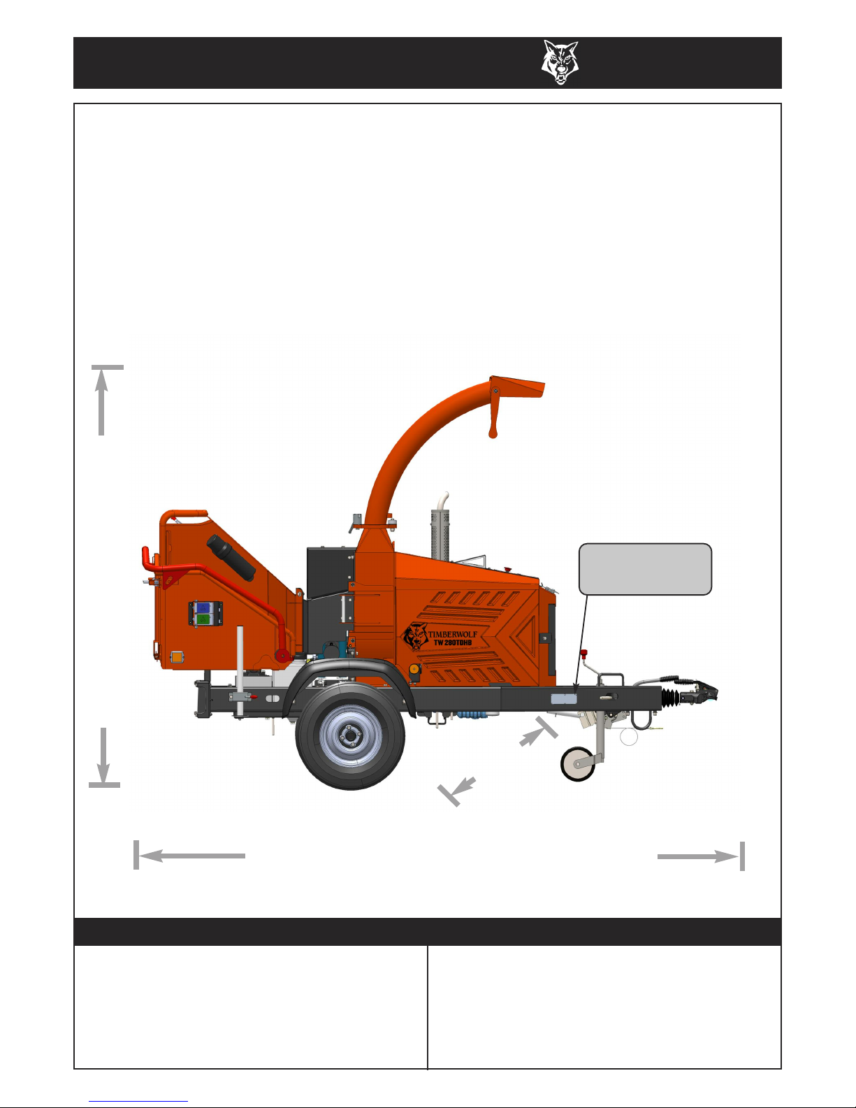
Serial No. Location
The serial number can be
found on the identification plate
located on the chassis beam.
Designed to chip solid wood material up to 200mm in diameter and
capable of chipping up to 6.5 tonnes of brushwood per hour.
DIMENSIONS
2370 mm, (1510 mm with discharge removed)
1640m
m
TIMBERWOLF TW 280TDHB (FIXED TOWHEAD) SPECIFICATION
Engine type Kubota 4-cylinder turbo diesel
Maximum power 33kW (45hp)
Cooling method Water cooled
Overall weight 1180kg
Starting method Electric
Roller feed Twin series hydraulic motors
Maximum diameter material 210mm (8.26")
Fuel capacity 36 litres
Hydraulic oil capacity 15 litres
Material processing capacity up to 6.5 tonnes/hr
Fuel type Diesel
The Timberwolf TW 280TDHB
3860 mm with standard tow head (3330 mm with feed tray folded)
Page 6
TIMBERWOLF
TW 280TDHB
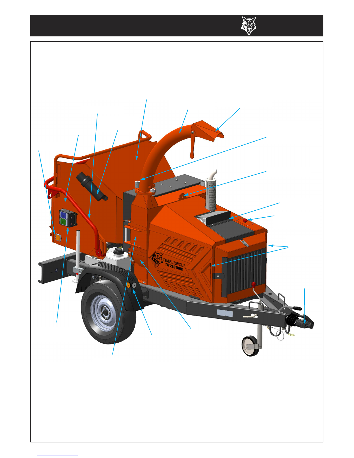
3
FUNNEL
DISCHARGE
TUBE
DISCHARGE
BUCKET
SAFETY BAR
LIFTING EYE
ENGINE
GUARDS
TOW HEAD
DISCHARGE
ADJUSTMENT
CONTROL
AIR INTAKE
REFLECTORS
REFLECTOR
PARTS LOCATOR
ROTOR
HOUSING
FEED TRAY
ACCESS
HATCH
CONTROL BOX
(each side)
EMERGENCY
STOP SWITCH
MANUAL
CANNISTER
Page 7
4
TIMBERWOLF
TW 280TDHB
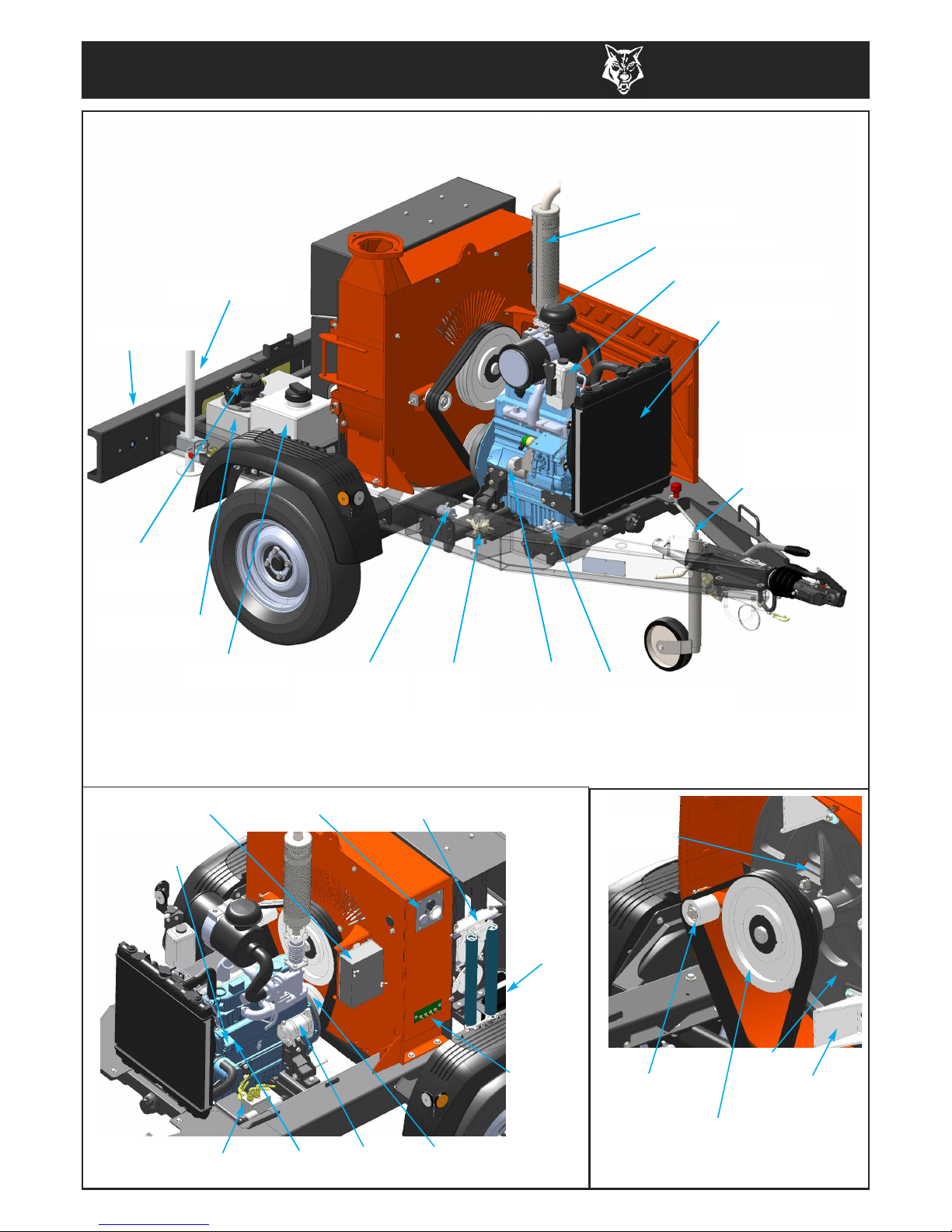
JOCKEY
WHEEL
ASSEMBLY
FUEL
PUMP
EXHAUST
FUEL FILTER
OIL FILTER
ALTERNATOR
CONTROL
PANEL
STARTER
MOTOR
RADIATOR
HYDRAULIC
PUMP
TOP ROLLER
SLIDE
DIRECTIONAL
CONTROL VALVE
IN-LINE
FUEL FILTER
AIR FILTER
RESERVE TANK
PARTS LOCATOR
FUEL TANK
HYDRAULIC
OIL TANK
HYDRAULIC
OIL FILTER
LIGHTBOARD
ELECTRICAL
PANEL
BATTERY
DRIVE
PULLEY
GREASING
PANEL
CUTTER
BLADE X 2
FAN SECTION
X 4
ROTOR
ROTOR
PULLEY
BELT TENSION
ADJUSTER
PROP STAND
Page 8

TIMBERWOLF
TW 280TDHB
5
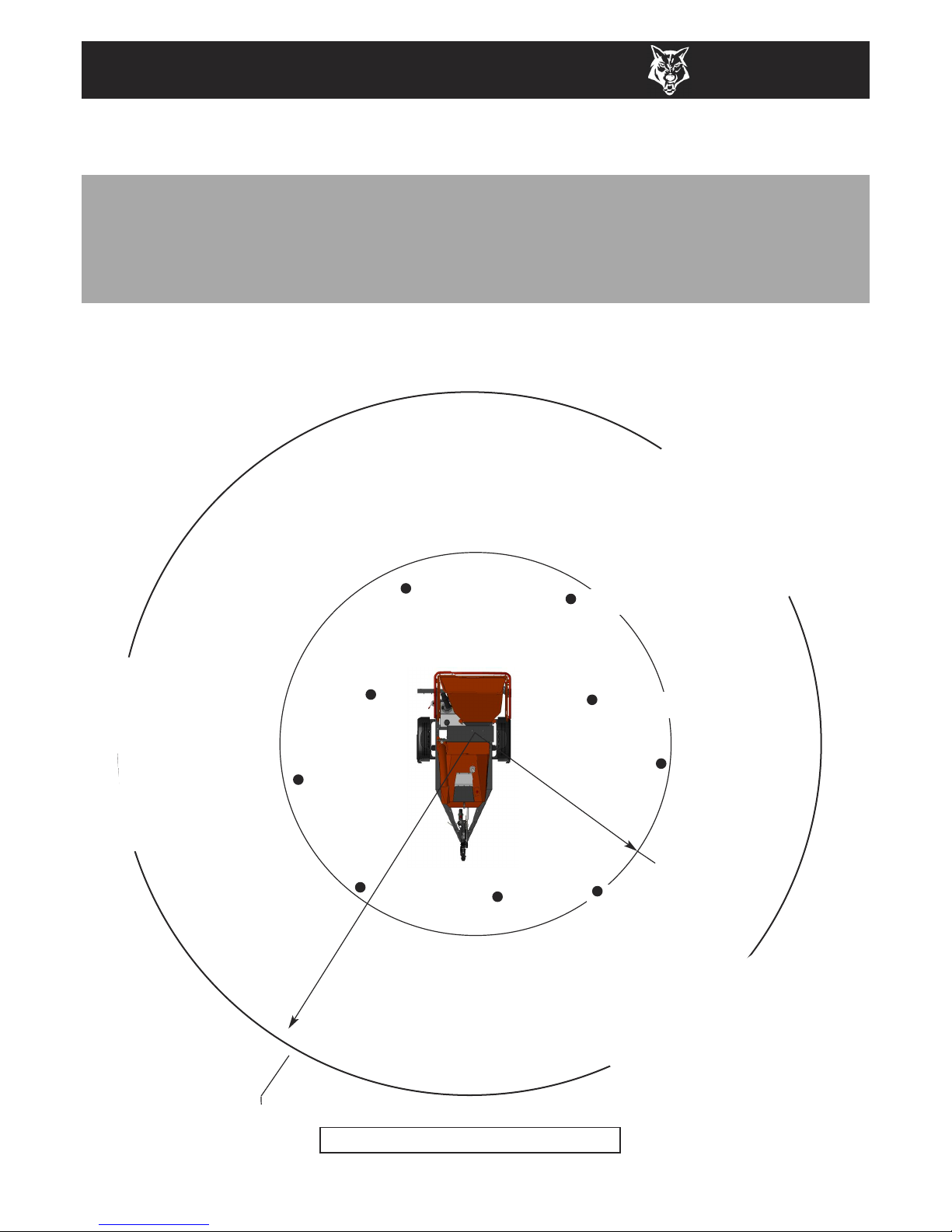
SAFE WORKING
BASIC WOODCHIPPING SAFETY
The operator should be aware of the following points:
MAINTAIN A SAFETY EXCLUSION ZONE around the chipper of at least 10 metres for the
general public or employees without adequate protection. Use hazard tape to identify this
working area and keep it clear from debris build up. Chips should be ejected away from any
area the general public have access to.
HAZARDOUS MATERIAL - Some species of trees and bushes are poisonous. The chipping
action can produce vapour, spray and dust that can irritate the skin. This may lead to
respiratory problems or even cause serious poisoning. Check the material to be chipped before
you start. Avoid confined spaces and use a facemask if necessary.
BE AWARE when the chipper is processing material that is an awkward shape. The material can
move from side to side in the funnel with great force. If the material extends beyond the funnel,
the brash may push you to one side causing danger. Badly twisted brash should be trimmed
before being chipped to avoid thrashing in the feed funnel.
BE AWARE that the chipper can eject chips out of the feed funnel with considerable force. Always
wear full head and face protection.
ALWAYS work on the side of the machine furthest from any local danger, e.g. not road side.
WARNING
The chipper will feed material through on its own. To do this, it relies on sharp
blades both on the feed rollers and the chipper rotor. To keep the blades sharp,
only feed the machine with clean brushwood. DO NOT put muddy/dirty wood,
roots, potted plants, bricks, stones or metal into the chipper.
OPERATOR'S PERSONAL PROTECTIVE EQUIPMENT REQUIRED
Chainsaw safety helmet fitted
with mesh visor and
recommended ear defenders to
the appropriate specifications.
Work gloves with elasticated
wrist.
Close fitting heavy-duty
non-snag clothing.
Face mask if
appropriate.
DO NOT
wear rings, bracelets, watches,
jewellery or any other items that
could be caught in the material
and draw you into the chipper.
Steel toe cap safety boots.
Page 9

6
TIMBERWOLF
TW 280TDHB
ü
GENERAL SAFETY MATTERS
D O ’ S A N D D O N ’ T S
DO NOT operate chipper unless available light is
sufficient to see clearly.
DO NOT use or attempt to start the chipper
without the feed funnel, guards and discharge unit
securely in place.
DO NOT stand directly in front of the feed funnel
when using the chipper. Stand to one side.
DO NOT allow -
DO NOT smoke when refuelling.
DO NOT let anyone who has not received
instruction operate the machine.
DO NOT climb on the machine at any time.
DONOT handle material that is partially engaged
in the machine.
DO NOT touch any exposed wiring while machine
is running.
DO NOT use the chipper inside buildings.
- to enter the machine, as damage is likely.
ALWAYS stop the chipper engine before making
any adjustments, refuelling or cleaning.
ALWAYS check rotor has stopped rotating and
remove chipper ignition key before maintenance
of any kind, or whenever the machine is to be left
unattended.
ALWAYS check the machine is well supported and
cannot move.
ALWAYS operate the chipper with the engine set
to maximum speed when chipping.
ALWAYS check (visually) for fluid leaks.
ALWAYS take regular breaks. Wearing personal
protective equipment for long periods can be
tiring and hot.
ALWAYS keep hands, feet and clothing out of feed
opening, discharge and moving parts.
ALWAYS use the next piece of material or a push
stick to push in short pieces. Under no
circumstances should you reach into the funnel.
ALWAYS keep the operating area clear of people,
animals and children.
ALWAYS keep the operating area clear from
debris build up.
ALWAYS keep clear of the chip discharge tube.
Foreign objects may be ejected with great force.
ALWAYS ensure protective guarding is in place
before commencing work. Failure to do so may
result in personal injury or loss of life.
ALWAYS operate the chipper in a well ventilated
area - exhaust fumes are dangerous.
BRICKS STRING CLOTH PLASTIC STONES
METAL GLASS RUBBER ROOTS BEDDING
PLANTS
ü
SAFE WORKING
Page 10
TIMBERWOLF
TW 280TDHB
7
SAFE WORKING
Noise levels above 80dB (A) will be experienced at the working position. Wear ear protection
at all times to prevent possible damage to hearing. All persons within a 4 metre radius must also
wear good quality ear protection.
NOISE TEST
MACHINE: TW 280TDHB
NOTES:
Tested chipping 200mm x 200mm corsican pine 1.5m
in length
99.10 dB
92.20 dB
R= 4 metres
Guaranteed Sound Power: 118dB (A)
100.73 dB
As required by Annex III of Directive 2000/14/EC “Noise Emission in the environment by equipment for use outdoors”.
R= 10 metres
8
7
.
9
d
B
(
A
)
C
a
l
c
u
l
a
t
e
d
8
7
.
9
d
B
(
A
)
C
a
l
c
u
l
a
t
e
d
8
7
.
9
d
B
(
A
)
C
a
l
c
u
l
a
t
e
d
95.23 dB
91.90 dB
93.33 dB
92.60 dB
91.07 dB
95.27 dB
Page 11

• CHECK ball head is well greased.
• WIND jockey wheel assembly anticlockwise until
the tow head is above the height of the ball hitch
on the vehicle.
• REVERSE vehicle so the ball hitch is directly below
the tow head.
• ATTACH breakaway cable to a strong point on the
vehicle, not the ball hitch.
• GRASP handle on tow head and push back catch
with thumb.
• WIND jockey wheel assembly clockwise, to lower
the tow head onto the ball hitch.
• RELEASE handle and continue to wind jockey
wheel clockwise. The tow head should snap into
place on the ball hitch. If it doesn't, repeat
previous 2 steps.
• WIND jockey wheel up until fully retracted and the
jockey wheel frame is seated in its notch on the
stem. The chipper weight should be fully on the
vehicle.
• RELEASE jockey wheel clamp and slide the jockey
wheel assembly fully up.
• TIGHTEN clamp on jockey wheel assembly.
• CONNECT electrical plug to socket on rear of
towing vehicle and check operation of all the trailer
and vehicle lights.
• THE chipper is now properly attached to the vehicle.
SAFE TRANSPORTATION
WARNING
DO NOT RIDE ON THE
CHIPPER WHEN IT IS
BEING TOWED.
HITCHING ONTO THE TOW BALL
UNHITCHING THE CHIPPER
Wen the chipper is unhitched it should be made secure
before starting work by applying the handbrake and
lowering the jack stand and jockey wheel (b).
When hitched to a vehicle the chipper handbrake
should be released and the jack stand and jockey
wheel stored in the towing position (a).
• ENSURE the chipper will not roll away after being
disconnected from the vehicle.
• DISCONNECT the electrical cable from the
vehicle socket.
• RELEASE breakaway cable.
• RELEASE the jockey wheel assembly clamp.
• LOWER the jockey wheel assembly fully.
• RETIGHTEN the jockey wheel assembly clamp.
• WIND the jockey wheel assembly anticlockwise until it
starts to take the weight of the chipper.
• GRASP the handle and release the catch with
your thumb.
• CONTINUE to wind the jockey wheel anticlockwise.
This should lift the tow head clear of the ball hitch.
• DRIVE the vehicle clear of the chipper.
• WIND the jockey wheel assembly to a suitable
point where the chipper is level.
• THE chipper is now fully detached from the vehicle.
• WHEN towing a chipper the maximum speed limit
i
s 60 mph.
• ON rough or bumpy road surfaces reduce speed
accordingly to protect your machine from
unnecessary vibration.
• WHEN towing off road be aware of objects that
may catch the chipper undergear.
• WHEN towing off road ensure inclination is not
excessive.
• AVOID excessively pot holed ground.
• WHEN reversing the chipper the short wheel base
will react quickly to steering.
• ALWAYS check the discharge is tight before moving.
• KEEP tyre pressures inflated to 3.4 bar or 50 psi.
• CHECK wheel nuts are tightened to 90Nm or 65 lbs ft.
• CLEAR loose chippings and debris from t he
machine before departing.
• ENSURE feed funnel is closed and the catch is
properly engaged before departing.
(a)
(b)
STABILISING THE CHIPPER
8
TIMBERWOLF
TW 280TDHB
OPERATING INSTRUCTIONS
Page 12

TIMBERWOLF
TW 280TDHB
9
OPERATING INSTRUCTIONS
All Timberwolf TW 280TDHB machines have a full pre - delivery inspection before leaving the factory and
are ready to use. Read and understand this instruction manual before attempting to operate the
chipper. In particular, read pages 5-7 which contain important health and safety information and advice.
CHAINSAW safety helmet fitted with visor
and recommended ear defenders to an
appropriate specification.
HEAVY-DUTY gloves with elasticated wrist area.
CLOSE - FITTING heavy-duty non-snag clothing.
SAFETY footwear.
FACE MASK (if appropriate).
See page 5 for more detailed information.
DELIVERY
OPERATOR’S PERSONAL PROTECTIVE EQUIPMENT REQUIRED
GREEN
FORWARD
FEED
PANEL
BLUE
REVERSE
FEED
PANEL
RED SAFETY BAR
Do not rely on the red bar to keep the roller
stationary if it is necessary to clear or touch the
roller. Always switch off the machine and remove
ignition key before approaching the roller.
There are two control boxes, located on either
side of the feed tray.
Roller control boxes- a control box is located on either side of the feed funnel. Their function is to
control the feed roller whilst processing material. They do not control the main rotor.
RED SAFETY BAR = This is the large red bar that surrounds the feed tray and side of the feed funnel.
The bar is spring loaded and connected to a switch that will interrupt the power to the rollers. The
switch is designed so that it only activates if the bar is pushed to the limit of its travel. The rollers stop
instantly, but can be made to turn again by pressing either the GREEN FEED or BLUE REVERSE
control buttons.
MANUAL CONTROLS
WARNING
DO NOT remove, jam, disable, bypass, override or otherwise
impede the effectiveness of the red safety bar.
Control Box Diagram
GREEN BUTTON = Forward feed - Push the button once - this activates the rollers and will allow you
to start chipping (if the rotor speed is high enough).
BLUE BUTTON = Reverse feed - allows you to back material out of the rollers. The rollers will only turn
in reverse as long as you keep pressing the button.
Page 13

10
TIMBERWOLF
TW 280TDHB
The engine management unit controls the feed rate of the material going into the chipping chamber. If
the engine speed is below the predetermined level, the engine management unit will not allow the feed
rollers to work in the forward “infeed” direction, until the rotor speed rises above the predetermined
level. At this point, the feed rollers will start turning without warning. The reverse function will work at
any engine speed.
LOCATE the machine on firm level ground.
CHECK machine is well supported and cannot
move.
CHECK jack stand is lowered and secure.
CHECK all guards are fitted and secure.
CHECK the discharge unit is in place and
fastened securely.
CHECK discharge tube is pointing in a safe
direction.
CHECK the feed funnel to ensure no objects
are inside.
CHECK feed tray is in up position - to prevent
people reaching rollers.
CHECK controls as described on page 11.
CHECK (visually) for fluid leaks.
CHECK fuel and hydraulic oil levels.
For parts location see diagrams on pages 3 & 4.
AUTO CONTROLS
OPERATING INSTRUCTIONS
ROTATION
1. Slacken nut using
integral handle.
2. Rotate tube.
3. Retighten nut.
1
DISCHARGE CONTROLS
DAILY CHECKS BEFORE STARTING
Controlling the discharge is an essential part of safe working.
BUCKET ANGLE
4. Adjust the bucket to the desired
angle using the handle provided.
There are two ways of stopping the TW 280TDHB chipper in the event of an emergency.
STOPPING THE ROLLERS
-Activating the red safety bar will stop the rollers immediately. To restart the rollers, just push the green
forward button or blue reverse button.
STOPPING THE ENGINE
Should the entire machine need to be stopped in an emergency, the red button on top of the engine
guard should be pushed. This will shut down the engine in the shortest possible time. The engine
cannot be restarted until the button is pulled out and the main ignition switch is turned off to reset the
machine.
EMERGENCY STOPPING
Page 14

TIMBERWOLF
TW 280TDHB
11
OPERATING INSTRUCTIONS
IT IS ESSENTIAL TO CARRY OUT THE FOLLOWING TESTS to check safety equipment - this
sequence of tests will only take a few seconds to carry out. We recommend that these tests are
carried out daily. Observing the function as described will confirm that the safety circuits are working
correctly. This is also a good opportunity to remind all operators of the control and emergency stop
systems.
MOVE the throttle lever to the ‘Tortoise’ to reduce the engine speed to idle.
LEAVE the engine running for 1 minute.
TURN the power switch to position 0. The engine should stop after a few seconds.
REMOVE the ignition key.
For more detailed information refer to the Engine Owner’s Manual
BEFORE USING THE CHIPPER
STOPPING THE ENGINE
The engine has two throttle settings, idle and fast. These are controlled by the
throttle lever on the funnel. Moving the lever towards the ‘Hare’ on the pictogram
will increase engine speed while moving it towards the ‘Tortoise’ will decrease
engine speed.
CONTROLLING THE ENGINE SPEED
3
1
2
PRESS THE GREEN
BUTTON
THE IN-FEED
SHOULD TURN FORWARDS
PRESS THE RED
SAFETY BAR
THE IN-FEED
SHOULD STOP
PRESS THE BLUE BUTTON
THE IN-FEED SHOULD TURN
BACKWARDS ONLY WHILE THE
BUTTON IS PRESSED
WITH THE ENGINE RUNNING AT FULL SPEED
STARTING THE ENGINE
0
1
2
HOURS
0
0
0
0
0
0
0
HOURS COUNTER
12V SOCKET
START
HEAT
OFF
ON
0
1
2
The engine controls are in two locations. The engine ignition is on the control panel in the centre of the
machine, and the throttle lever is on the bonnet next to the engine emergency stop switch (see parts
locator on page 3).
ENSURE throttle lever is in the slow
(tortoise) position.
INSERT key. Turn to heat.
HEATER LED comes on.
WAIT FOR HEATER LED TO GO OUT.
TURN key to engage starter motor.
RELEASE key once engine starts.
When the emergency stop button is pressed it must be pulled out again and the ignition switch
turned off to reset the machine before attempting to restart.
ENGINE CONTROLS
Do not engage starter motor for more than 20 seconds - allow one minute
before attempting to start. Investigate reasons for failure to start.
Page 15

12
TIMBERWOLF
TW 280TDHB
CHECK that the chipper is running smoothly.
RELEASE the catches on the feed tray and
lower. Pull to release the red stop button.
PERFORM the “before using the chipper”
tests (see page 11).
WHEN the chipper is unhitched it should be
made secure before starting work by applying
the handbrake and lowering the jack stand
and jockey wheel
PRESS the green control button. The rollers
will commence turning.
STAND to one side of the feed funnel.
PROCEED to feed material into the feed
funnel.
STARTING TO CHIP
CHIPPING
WARNING
Do not use or attempt to start the chipper without the protective
guarding and discharge unit securely in place. Failure to do so may
result in personal injury or loss of life
.
Wood up to the recommended diameter can be fed into the feed funnel. Put the butt end in first and
engage it with the feed roller. The hydraulic feed rollers will pull the branch into the machine quite
quickly. Large diameter material will have its feed rate automatically controlled by the engine
management unit.
Sometimes a piece of wood that is a particularly awkward shape is too strong for the feed rollers to
break. This will cause the top roller to either bounce up and down on the wood or both rollers to stall.
If this occurs press the
BLUE REVERSE button until the material has been released. Pull the material
out of the feed funnel and trim it so the chipper can handle it.
Both feed rollers should always turn at the same speed. If one or both rollers stop or suddenly slow
down it may be that a piece of wood has become stuck behind one of the rollers. If this occurs press
the
BLUE REVERSE button and hold for 2 seconds - then repress GREEN FEED button. This should
enable the rollers to free the offending piece of material and continue rotation at the correct speed. If
the rollers continue to stall in the 'forward feed' or 'reverse feed' position push the
RED STOP BUTTON,
turn engine off, remove ignition key and investigate.
OPERATING INSTRUCTIONS
BLADE WEAR
The most important part of using a wood chipper is keeping the cutter blades sharp. Timberwolf
chipper blades are hollow ground to an angle of 40 degrees. When performing daily blade checks
ensure blade edge is sharp and free from chips, if there is any evidence of damage, or the edge is “dull”
change the blade(s). The TW 280TDHB is fitted with 2 blades 158mm (6") long. It is 100 mm wide
when new. A new blade should chip for up to 25 hours before it requires sharpening. This figure will
be drastically reduced by feeding the machine with stony, sandy or muddy material.
As the blade becomes blunt, performance is reduced. With increased stress and load on the machine
the chips will become more irregular and stringy. At this point the blade should be sent to a reputable
blade sharpening company. The blade can be sharpened several times in its life. A wear mark on the
reverse side indicates the safe limit of blade wear. Replace when this line is exceeded.
The machine is also fitted with a static blade (anvil). It is important that the anvil is in good condition
to allow the cutting blades to function efficiently. Performance will be poor, even with sharp cutter
blades, if the anvil is worn.
Page 16

TIMBERWOLF
TW 280TDHB
13
OPERATING INSTRUCTIONS
Always be aware that what you are putting into the chipper must come out. If the chips stop coming
out of the discharge tube but the chipper is taking material in - STOP IMMEDIATELY. Continuing to feed
material into a blocked machine may cause damage and will make it difficult to clear.
If the chipper becomes blocked, proceed as follows:
STOP the engine and remove the ignition keys.
REMOVE the discharge tube. Check that it is clear.
WEARINGgloves, reach into the rotor housing and scoop out the majority of the debris
causing the blockage.
REPLACE the discharge tube.
RESTART the engine and increase to full speed.
IN the event of heavy blockages the access hatch can be removed (see parts locator on page 3).
ALLOW machine time to clear excess chips still remaining in rotor housing before you continue
feeding brushwood. Feed in a small piece of wood while watching to make sure that it comes out of
the discharge. If this does not clear it, repeat the process and carefully inspect the discharge tube to
find any obstruction.
NOTE
Continuing to feed the chipper with brushwood once it has become blocked will cause the chipper to
compact the chips in the rotor housing and it will be difficult and time consuming to clear.
AVOID THIS SITUATION - WATCH THE DISCHARGE TUBE AT ALL TIMES.
BLOCKAGES
WARNING
Do not reach into the rotor housing with unprotected hands. There
are sharp blades and any small movement of the rotor may cause
serious injury.
This can be viewed through the wall of the tank. Maximum and minimum marks are provided.
HYDRAULIC OIL LEVEL INDICATOR
FUEL LEVEL INDICATOR
The fuel level can be seen through the wall of the fuel tank.
Page 17

14
TIMBERWOLF
TW 280TDHB
SERVICE INSTRUCTIONS
THE FOLLOWING PAGES DETAIL ONLY
BASIC MAINTENANCE GUIDELINES SPECIFIC
TO YOUR CHIPPER.
THIS IS NOT A WORKSHOP MANUAL.
THE FOLLOWING GUIDELINES ARE NOT EXHAUSTIVE AND DO NOT EXTEND
TO GENERALLY ACCEPTED STANDARDS OF ENGINEERING/MECHANICAL
MAINTENANCE THAT SHOULD BE APPLIED TO ANY PIECE OF MECHANICAL
EQUIPMENT AND THE CHASSIS TO WHICH IT IS MOUNTED.
AUTHORISED TIMBERWOLF SERVICE AGENTS ARE FULLY TRAINED IN ALL
ASPECTS OF TOTAL SERVICE AND MAINTENANCE OF TIMBERWOLF
WOOD CHIPPERS. YOU ARE STRONGLY ADVISED TO TAKE YOUR CHIPPER TO
AN AUTHORISED AGENT FOR ALL BUT THE MOST ROUTINE MAINTENANCE
AND CHECKS.
TIMBERWOLF ACCEPTS NO RESPONSIBILITY FOR THE FAILURE OF THE
OWNER/USER OF TIMBERWOLF CHIPPERS TO RECOGNISE GENERALLY
ACCEPTED STANDARDS OF ENGINEERING/MECHANICAL MAINTENANCE
AND APPLY THEM THROUGHOUT THE MACHINE.
THE FAILURE TO APPLY GENERALLY ACCEPTED
STANDARDS OF MAINTENANCE, OR THE PERFORMANCE
OF INAPPROPRIATE MAINTENANCE, MAY INVALIDATE
WARRANTY IN WHOLE OR IN PART.
PLEASE REFER TO YOUR AUTHORISED
TIMBERWOLF SERVICE AGENT FOR
SERVICE AND MAINTENANCE.
Page 18

TIMBERWOLF
TW 280TDHB
15
WARNING
Always immobilise the machine by stopping the engine, removing
the ignition key and disconnecting the battery before undertaking
any maintenance work.
SERVICE SCHEDULE
SERVICE INSTRUCTIONS
SERVICE SCHEDULE
Check water.
ü
Check radiator is clear.
ü
Check engine oil - top up if necessary (10W-30).
ü
Check for engine oil / hydraulic oil leaks.
ü
Check fuel level.
ü
Check feed funnel, feed roller cover, access covers,
engine covers and discharge unit are securely fitted.
ü
Check blades.
ü
Clean air filter element.
Check tyre pressure is 3.4 Bar (50 psi).
ü
Check safety bar mechanism.
ü
Check for tightness all nuts, bolts and fastenings
making sure nothing has worked loose.
ü
Grease discharge flange.
ü
Check tension of main drive belts
(and tension if necessary).
ü
Grease the roller box slides.
ü
Grease the roller spline and bearing.
ü
Check anvils for wear.
ü
Check fuel pipes and clamp bands.
ü
Check for loose electrical wiring.
ü
Replace hydraulic oil filter - every year or 100 hours
after service or repair work to the hydraulic system.
ü ü
Replace hydraulic oil.
ü ü
Replace fuel pipes and clamp bands.
Check coolant.
Change engine oil.
Replace engine oil filter cartridge.
Check valve clearance.
Replace anvils when worn.
Axle maintenance.
Tow head maintenance.
Daily
Check 50Hours
100
Hours
500
Hours 1Year
REFER TO YOUR ENGINE
SUPPLIERS MANUAL
DEPENDING ON WORKING ENVIRONMENT
REFER TO SUPPLIERS
INSTRUCTION SHEET
OR
OR
RETURN TO DEALER FOR ANVIL CHANGE
NOTE: Your Timberwolf woodchipper is covered by a full 12 months parts and labour warranty. Subject to
correct maintenance and proper machine usage, the bearings are guaranteed for 12 months regardless of hours
worked by the machine. In conditions of 'heavy usage' - i.e. in excess of 500 hours per year - it is recommended
that the bearings are changed annually to ensure that the machine retains optimum working performance.
To assess the wear condition of the braking system, and troubleshoot any problems relating to the braking
system or axle, please refer to the 'Brake Operation Handbook' and 'AL-KO document 580458' as supplied.
OR AS REQUIRED - SEE PAGE 21
OR AS REQUIRED - SEE PAGE 21
Page 19

16
TIMBERWOLF
TW 280TDHB
SERVICE INSTRUCTIO
NS
HANDLE blades with extreme caution to
avoid injury. Gloves should always be
worn when handling the cutter blades.
THE drive belts should be connected
while changing blades, as this will restrict
sudden movement of the rotor.
THE major components of this machine
are heavy. Lifting equipment must be
used for disassembly.
CLEAN machines are safer and easier to
service.
AVOID contact with hydraulic oil.
ALWAYS IMMOBILISE THE ENGINE BEFORE UNDERTAKING ANY MAINTENANCE WORK ON
THE CHIPPER BY REMOVING THE KEY AND DISCONNECTING THE BATTERY.
Only fit genuine Timberwolf replacement blades, screws and chipper spares. Failure to do so
will result in the invalidation of the warranty and may result in damage to the chipper, personal
injury or even loss of life.
The lifting eye is designed to lift the machine’s weight only. Do not
use hoist hook directly on the lifting eye, use a correctly rated safety
shackle. Inspect the lifting eye prior to each use - DO NOT USE
LIFTING EYE IF DAMAGED.
SAFE MAINTENANCE
SAFE LIFTING OF THE CHIPPER
BATTERY REMOVAL AND MAINTENANCE
CHECK FITTINGS
SPARES
The Timberwolf TW280TDHB is subject to large vibrations during the normal course of operation.
Consequently there is always a possibility that nuts and bolts will work themselves loose. It is
important that periodic checks are made to ensure the security of all fasteners. Fasteners should be
tightened using a torque wrench to the required torque (see below). Uncalibrated torque wrenches
can be inaccurate by as much as 25%. It is therefore essential that a calibrated torque wrench
is used to achieve the tightening torques listed below.
WARNING
Refer to the battery safety section on page 17 - 18.
Size Pitch Head Torque Ib ft
Blade Bolts M16 Standard 24mm Hex 125
Anvil Bolts M12 Standard 10mm Allen Hex 65
General M8 Standard 13 mm Hex 20
General M10 Standard 17 mm Hex 45
General M12 Standard 19 mm Hex 65
Drain Bung in Fuel Tank 3/8” BSP - 22 mm Hex 25
1. The battery can be located under the funnel.
2. Remove the negative lead first and then the positive lead.
3. Clean, charge and/or top up the battery as required.
4. Refitting is the reverse of removal. Apply a smear of vaseline to the terminals to prevent
corrosion.
Page 20

TIMBERWOLF
TW 280TDHB
17
WARNING NOTES AND SAFETY REGULATIONS FOR FILLED LEAD-ACID BATTERIES
For safety reasons, wear eye protection
when handling a battery.
Keep children away from acid and
batteries.
Fires, sparks, naked flames and smoking are
prohibited.
-Avoid causing sparks when dealing with cables
and electrical equipment, and beware of
electrostatic discharges.
-Avoid short circuits.
Explosion hazard:
-A highly explosive oxyhydrogen gas mixture is
produced when batteries are charged.
Corrosive hazard:
-Battery acid is highly corrosive, therefore:
-Wear protective gloves and eye protection.
-Do not tilt the battery, acid may escapefrom the
vent openings.
First aid:
-Rinse off acid splashed in the eyes immediately
for several minutes with clear water! Then
consult a doctor immediately.
-Neutralise acid splashes on the skin or clothes
immediately with acid neutraliser (soda) or soap
suds, and rinse with plenty of water.
-If acid is swallowed, consult a doctor immediately.
Warning notes: The battery case can become brittle, to
avoid this:
-Do not store batteries in direct sunlight.
-Discharged batteries may freeze up, therefore
store in an area free from frost.
Disposal:
-Dispose of old batteries at an authorised
collection point.
-The notes listed under item 1 are to be followed
for transport.
-Never dispose of old batteries in household
waste.
Product name: Copper Ease.
Copper Ease contains no hazardous ingredients at or above regulatory disclosure limits, however,
safety precautions should be taken when handling (use of oil-resistant gloves and saftey glasses are
recommended - respiratory protection is not required). Avoid direct contact with the substance and
store in a cool, well ventilated area avoiding sources of ignition, strong oxidising agents and strong
acids. Dispose of as normal industial waste (be aware of the possible existance of regional or national
regulations regarding disposal), do not discharge into drains or rivers.
In case of fire: in combustion the product emits toxic fumes, extinguish with alcohol or polymer foam,
carbon dioxide or dry chemical powder. Wear self-contained breathing apparatus and protective clothing
to prevent contact with skin and eyes.
FIRST AID
Skin contact: there may be mild irritation at the site of contact, wash immediately with plenty of soap
and water.
Eye contact: there may be irritation and redness, bathe the eye with running water for 15 minutes.
Ingestion: there may be irritation of the throat, do not induce vomiting, wash out mouth with water.
A safety data sheet for this product can be obtained by writing to the manufacturer at the
following address: Comma Oil and Chemicals Ltd., Deering Way, Gravesend, Kent DA12 2QX.
Tel: 01474 564311, Fax: 01474 333000.
BATTERY SAFETY INFORMATION
COPPER EASE SAFETY INFORMATION
SERVICE INSTRUCTIONS
Page 21

18
TIMBERWOLF
TW 280TDHB
1. Storage and transport
- Batteries are filled with acid.
- Always store and transport batteries upright
and prevent from tilting so that no acid can
escape.
- Store in a cool and dry place.
- Do not remove the protective cap from the
positive terminal.
- Run a FIFO (first in-first out)warehouse
management system.
2. Initial operation
- The batteries are filled with acid at a density of
1.28g/ml during the manufacturing process and
are ready for use.
- Recharge in case of insufficient starting power
(cf. section 4).
3. Installation in the vehicle and removal from
the vehicle
- Switch off the engine and all electrical
equipment.
- When removing, disconnect the negative
terminal first.
- Avoid short circuits caused by tools, for example.
- Remove any foreign body from the battery tray,
and clamp battery tightly after installation.
- Clean the terminals and clamps, and lubricate
slightly with battery grease.
- When installing, first connect the positive
terminal, and check the terminal clamps for
tight fit.
- After having fitted the battery in the vehicle,
remove the protective cap from the positive
terminal, and place it on the terminal of the
replaced battery in order to prevent short
circuits and possible sparks.
- Use parts from the replaced battery, such as
the terminal covers, elbows, vent pipe
connection and terminal holders (where
applicable); use available or supplied filler caps.
- Leave at least one vent open, otherwise there
is a danger of explosion. This also applies
when old batteries are returned.
4. Charging
- Remove the battery from the vehicle;
disconnect the lead of the negative terminal first.
- Ensure good ventilation.
- Use suitable direct current chargers only.
- Connect the positive terminal of the battery to
the positive output of the charger. Connect the
negative terminal accordingly.
- Switch on the charger only after the battery has
been connected, and switch off the charger first
after charging has been completed.
- Charging current-recommendation: 1/10
ampere of the battery capacity Ah.
- Use a charger with a constant charging voltage
of 14.4V for re-charging.
- If the acid temperature rises above 55
o
Celsuis,
stop charging.
- The battery is fully charged when the charging
voltage has stopped rising for two hours.
5. Maintenance
- Keep the battery clean and dry.
- Use a moist anti-static cloth only to wipe the
battery, otherwise there is a danger of
explosion.
- Do not open the battery.
- Recharge in case of insufficient starting power
(cf. section 4).
6. Jump Starting
- Use the standardised jumper cable in
compliance with DIN 72553 only, and follow the
operating instructions.
- Use batteries of the same nominal voltage only.
- Switch off the engines of both vehicles.
- First connect the two positive terminals (1) and
(2), then connect the
negative terminal of the
charged battery (3) to a
metal part (4) of the
vehicle requiring
assistance away from the battery.
- Start the engine of the vehicle providing
assistance, then start the engine of the vehicle
requiring assistance for a maximum of 15
seconds.
- Disconnect the cables in reverse sequence
(4-3-2-1).
7. Taking the battery out of service
- Charge the battery; store in a cool place or in
the vehicle with the negative terminal
disconnected.
- Check the battery state of charge at regular
intervals, and correct by recharging when
necessary (cf. section 4).
(1)
(2)
(3)
(4)
12V
12V
BATTERY SAFETY INFORMATION...cont.
SERVICE INSTRUCTIONS
Page 22

TIMBERWOLF
TW 280TDHB
19
SERVICE INSTRUCTIONS
13 Reassemble the blades, bolts, washers and
nuts in the order shown in the diagram
above. Use only genuine Timberwolf nuts
and washers, as they are of a higher grade
than normally stocked at fastener factories.
Failure to use the appropriate grade nuts or
washers may result in damage, injury or
death. The use of genuine Timberwolf
blades and bolts is recommended.
14 Apply a smear of anti seize compound
(copper ease) to the bolt threads and back
face of the nuts. Do not apply copper grease
onto the counter bore faces of the blades or
bolts.
15 A calibrated torque wrench must be used
to tighten the bolts to a torque setting of
125 lbs ft (170 Nm).
16 Remove lock pin, rotate rotor to next blade
then replace lock pin and repeat steps 6 - 14.
17 Refit access hatch.
18 Refit the nuts and tighten to 40lb/ft.
19 Refit battery leads.
CHANGE BLADES
WARNING
Wear riggers gloves for the blade changing operation.
WARNING
Always sharpen blades on a regular basis. Failure to do so
will cause the machine to under perform and will overload
engine and bearings causing machine breakdown. Blades
must not be sharpened beyond the wear mark (see diagram).
Failure to comply with this could result in machine damage,
injury or loss of life.
WEAR MARK
3
4
5
10
Turn the chipper off and remove the ignition keys.1
Remove battery leads.2
Remove the 3 nuts retaining the access hatch,3
slide hatch clear of rotor housing.
Turn rotor to blade change position.4
Insert locking bar into rotor housing and rotor.5
Brush away all dirt and debris from the rotor6
and blades.
With a 24mm spanner/socket undo the 2 nyloc7
nuts and washers that are holding the blade in
place.
Remove blade bolts while holding blade in8
position. The inner bolt on the inner blade
passes through the hole in the roller box. If
necessary tap the bolts to loosen.
Grasp the blade by the flat edges while9
wearing heavy duty gloves.
Withdraw the blade from the rotor. 10
Rotate blade to use 2nd edge or replace with11
a new or sharpened blade.
Clean the back surface of the blade, blade12
bolts and blade area of the rotor before
reseating blades.
The blades must not have
any material underneath them when tightened.
If they are not flat and tight they will become
loose very quickly.
8
Page 23

20
TIMBERWOLF
TW 280TDHB
TENSION DRIVE BELTS
1. Remove side panel.
2. Loosen bolt in centre of tensioner pulley with a 19 mm spanner
so that pulley is able to slide with minimal wobble.
3. Turn nut in end of tensioner pulley slider until correct belt
tension is achieved. For instructions on checking belt tension
& correct belt tension values, please refer to the Timberwolf
V-Belt Tensioning Data Table at the end of the manual.
5. Re-tighten bolt in centre of tensioner pulley.
6. Run machine and test, recheck belt tension.
7. NOTE: Slack drive belts will cause poor performance and excess
belt and pulley wear.
2
3
NOTE:There will normally be a rapid drop in tension during run-in period for new belts. When new
belts are fitted, check the tension every 2 - 3 hours and adjust until the tension remains constant.
Belt failures due to lack of correct tensioning will not be covered under your Timberwolf warranty.
NOTE: This is a non-adjustable
air breather filter.
WARNING
Use plastic gloves to keep oil off skin and dispose of the used oil
and filter in an ecologically sound way. The oil and filter should be
changed once a year or at any time it becomes contaminated.
Before starting check that the chipper is standing level and brush
away loose chips.
1. Remove the black screw cap from the top of the
filter housing.
2. Partially remove filter element from inner cup.
Leave filter to drain for 15 minutes.
3. Remove filter element from cup when clear of
hydraulic oil.
4. Remove drain plug and drain oil into a suitable
container.
5. Replace drain plug.
6. Refill with VG 32 hydraulic oil until the level is
between the min and max lines on the tank (about
15 litres).
7. Refit the filter cup, install a new filter element and
refit the black screw cap, to the filter housing,
ensuring o-ring remains in place.
CHANGE HYDRAULIC OIL AND FILTER
All the hydraulic hoses should be regularly inspected for chafing and leaks. The hydraulic system is
pressurized to 150 Bar (2175 PSI) and thus the equipment containing it must be kept in good condition.
Identify the hoses that run to the top motor. These have the highest chance of damage as they are
constantly moving. If any hydraulic components are changed new seals should be installed during
reassembly. Fittings should then be retightened.
CHECK HOSES
1
2
SERVICE INSTRUCTIONS
Page 24

TIMBERWOLF
TW 280TDHB
21
ENGINE SERVICING
All engine servicing must be performed in accordance with the Engine Manufacturer’s Handbook
provided with the machine. FAILURE TO ADHERE TO THIS MAY INVALIDATE WARRANTY
AND/OR SHORTEN ENGINE LIFE.
SERVICE INSTRUCTIONS
1. Remove the discharge tube.
2. Apply multipurpose grease to surface shown.
3. Refit discharge tube.
2
GREASE THE DISCHARGE FLANGE
NOTE:This should be done regularly. In dirty and dusty conditions or during periods of hard
work it should be daily. If the bearings and splines are allowed to run dry premature wear will
occur resulting in a breakdown and the need for replacement parts. This failure is not warranty.
Early signs of insufficient grease includes squeaking or knocking rollers.
NOTE: This should be done regularly. In dirty or dusty
conditions or during periods of hard work it should be
done weekly. If the slides become dry the top roller will
tend to hang up and the pulling-in power of the rollers will
be much reduced. Excessive wear will ensue.
1. Turn the chipper off and remove the ignition keys.
2. Ensure machine has come to a complete stop - remove battery leads.
3. Remove the 6 nuts and washers retaining the roller box guard and
remove guard.
4. Remove the blade access hatch as blade change procedure.
5. Apply thin grease with a brush directly to the slide surfaces
indicated, including inner cheeks of slider. DO NOT USE
GRAPHITE BASED GREASE.
6. Replace access hatch then top guard. Refit nuts and washers.
7. Refit battery leads.
1
1. Locate the greasing panel.
2. Apply 4+ pumps of grease to each nipple.
3. It is recommended to grease all the nipples whilst the engine is
running and rollers are turning to distribute the grease evenly.
DO NOT USE GRAPHITE BASED GREASE.
4. Both front and rear bearings are greased by nipples A and B. The
top and bottom roller splines are greased by nipples C and D.
GREASE THE ROLLER SPLINE AND ROTOR BEARINGS
GREASE THE ROLLER BOX SLIDES
A
B
C
D
3
4
5
Page 25

22
WARRANTY STATEMENT
TIMBERWOLF
TW 280TDHB
ENTEC INDUSTRIES LTD 36 MONTH WARRANTY
WARRANTY
The warranty period for your Entec Industries Ltd machine commences on the date of sale to the first
end user and continues for a period of 36 months. This guarantee is to the first end user only and is not
transferable except when an Authorised Timberwolf Dealer has a machine registered with Entec
Industries Ltd as a hire chipper or long term demonstrator – in these situations they are duly authorised
to transfer any remaining warranty period to their first end user. Any warranty offered by the Timberwolf
Dealer beyond the original 36-month period will be wholly covered by said Dealer.
LIABILITY
No liability will be accepted for special, indirect, incidental, or consequential loss or damages of any kind.
Our obligation under this warranty is limited to repair at Entec Industries Ltd Authorised Timberwolf
Dealers or at Entec Industries Ltd premises.
WARRANTY STATEMENT
Entec Industries Ltd warrants to the first end user that:
Your machine shall be designed, built and equipped, at the point of sale, to meet all current•
applicable regulations.
Your machine shall be free from manufacturing defects both in materials and workmanship in•
normal service for the period mentioned above.
Normal wear & tear on consumable items and their routine maintenance or replacement are not
warrantable items.
Engine units are covered independently by their respective manufacturer warranties.
OWNERS WARRANTY RESPONSIBILITIES
As the owner of an Entec Industries Ltd machine you are responsible for the following:
Operation of the machine in accordance with the Entec Industries Ltd instruction manual.•
Performance of the required maintenance listed in your Entec Industries Ltd instruction manual.•
In the event of a failure the Entec Industries Ltd authorised Timberwolf dealer is to be notified•
within 10 days of failure and the equipment is to be made available for inspection by the dealer
technician.
WARRANTY RESTRICTIONS
The Entec Industries Ltd warranty is restricted to the first end user only and is not transferable except
when an authorised Timberwolf dealer has a wood chipper registered with Entec Industries Ltd as a hire
chipper or long term demonstrator – in these situations they are duly authorised to transfer any remaining
warranty period to their first end user.
The Entec Industries Ltd warranty may be invalidated if any of the following apply:
The failed parts or assembly is interfered with in any way.•
Normal maintenance has not been performed.•
Incorrect reassembly of components.•
The machine has undergone modifications not approved in writing by Entec Industries Ltd.•
In the case of tractor driven equipment, use has been on an unapproved tractor.•
Conditions of use can be deemed abnormal.•
The machine has been used to perform tasks contrary to those stated in the Entec Industries Ltd•
instruction manual.
WARRANTY SERVICE
To obtain warranty service please contact your nearest Entec Industries Ltd approved Timberwolf dealer.
To obtain details of the nearest facility please contact Entec Industries Ltd at the address on the back of
this manual. These warranty terms are in addition to and not in substitution for and do not affect any right
and remedies which an owner might have under statute or at common law against the seller of the goods
under the contract by which the owner acquired the goods.
Page 26

TIMBERWOLF
TW 280TDHB
23
Environmental Manufacturing LLP CE cert
Environmental Manufacturing LLP
Entec House,
Tomo Industrial Estate,
Stowmarket,
Suffolk IP14 5AY
Tel: 01449 765800 Fax: 01449 765801
EC Declaration of Conformity
Environmental Manufacturing LLP as the designer and manufacturer, certifies that the machine
stipulated below complies with all the relevant provisions of the:
Machinery Directive; 2006/42/EC
(& other relevant directives)
and the National Laws and Regulations adopting these directives.
Designer/Manufacturer : Environmental Manufacturing LLP
Description of Machinery : Self-powered portable machine intended to chip
up tree waste prior to disposal.
Model : TW 280TDHB
Serial No. : Serial Manufacture
BSI Transposed Harmonised Standards applied: (including parts/clauses of):
BS EN 12100-1: 2010 Safety of Machinery- Basic concepts, BS EN 13857-1: 2008 Safety of Machinery-Safety
distances to danger zones, BS EN 60204-1: 2006 +A1 2009 Safe electrical practices, BS EN 13732-1:2008
Safety of Machinery ± Temperatures of touchable surfaces, BS EN 13849-1: 2008 ± Safety of Machinery ±
Safety related parts of control systems, BS13850:2008 safety of Machinery Emergency stop BS EN 982: 1996
+ A1 2005 ± Safety of Machinery ± Hydraulics, BS EN 1088: 1995 + A2 2008 ± Safety of Machinery ±
Interlocking devices, BS EN 13525: 2005 + A2 2009 ± Forestry Machinery ± Wood chippers ± Safety. BS EN
953:1997+A1:2009
³5HVSRQVLEOH´3erson empowered to sign: __________________________Mr. Jeff Haines
Position in Company: Technical Director
Date: 15th April 2016
CERTIFICATE OF CONFORMITY
Page 27

24
E X A M P L E
IDENTIFICATION PLATE
TIMBERWOLF
TW 280TDHB
Page 28

TIMBERWOLF
TW 280TDHB
25
DECALS
Hot exhaust
Danger.
Rotating blades.
Keep hands and feet out.
High velocity discharge -
keep clear
Reverse feed
Personal Protective
Equipment required
Forward feed
Read the instruction
manual for greasing and
maintenance information
Warning
Do not engage starter motor for
more than 20 seconds. Allow one
minute before
attempting to start. Investigate
reasons for failure to start.
Excessive cranking will result in
starter motor failure. This will not be
covered under warranty.
The instruction manual with
this machine
contains important
operating, maintenance and
health and safety
information. Failure to
follow the information
contained in the
instruction manual may lead
to death or serious injury.
Push to stop.
Clean under blades before
refitting or turning.
Failure to do so may result in
blade(s) coming loose and
damage being caused to the
rotor housing.
Do not pull here.
New drive belts
need re-tensioning.
When new belts are fitted
check tension every 2-3 hours
& adjust until tension remains
constant.
Push to stop,
Pull to reset.
(engine)
Fuel Here.
Risk of fire. Allow engine
to cool for 1 minute before
refuelling.
Use diesel fuel only.
Decal Description
Decal Description
616
617
670
1661
1662
4
099
2
800
2949
3022
1399
P691
19517
18393
2801
P1301
Lifting eye is designed to lift
the machine’s weight only.
Do not use hoist hook on lifting
eye. Use correctly rated safety
shackle only through lifting eye.
Lifting eye to be inspected every
6 months or before each use.
Always visually inspect lifting
eye prior to each use. Do not
use lifting eye if damaged.
C192-0112
Page 29

26
DECALS
TIMBERWOLF
TW 280TDHB
D
anger.
Do not operate without this
cover in place.
Danger.
Rotating blades inside. Stop
engine and remove key before
r
emoving discharge unit.
C
aution. Do not put road
sweepings in machine as grit
will damage blades.
C
aution. When transporting,
discharge clamps may work
loose.Check frequently.
Caution.
Avoid standing
directly in front of feed funnel
to reduce exposure to noise,
dust and risk from
ejected particles.
Danger.
Do not use this
machine without the
discharge unit fitted. failure
to comply may result in
serious inury or damage.
Warning
Failure to maintain brake
adjustment will result in
damper failure. No warranty
liability will be accepted on
this item.
Danger. Autofeed system
fitted. Rollers may turn
without warning!
When the engine is switched
off the rollers will turn during
the run down period.
To go on relays.
Auto Back-off
Forward Latch
Engine Safety
Torque blade bolts to
125 lbs ft (170 Nm).
P637
P652
P655
P
653
P654
P656
P650
1258
D
ecal Description
Decal Description
C192 - 0100 C192 - 0101 18008 1363 P*2640
P*2743 P*2744 P*729
0
1
2
P1812
((
/
P1809
P1810
P1811
Page 30

TIMBERWOLF
TW 280TDHB
27
ELECTRICAL PARTS LOCATOR
Date Last Modified: 22.04.2016
Page 31

28
CIRCUIT DIAGRAM
DOCUMENT No. ISSUE
CIRCUIT DIAGRAM FOR: TW280 TDHB (H-BOX)
2
280-CD
19
50 30
KEY SWITCH
ACC
OFFACRUN
START
SPLIT TO FUNNEL LOOM
HOUR
FUEL
FUEL
SOLENOID
ROTOR
SWITCH EMERGENCY
SWITCH
1-AC 3mm
41 1mm12 .5mm
p
t
1mm40
15 1mm
1.5mm
16
WATER TEMP
SWITCH
OIL PRESS
SWITCH
LED
HEATERS
ON LED
LED
LED
POWER ON
FUSE 1
IGP
FUSE 2
AUX
1mm
2mm
15
5
14
BLUE
SP#4
0.5
AUX POWER
CONN
SOLENOID
FWD
REVERSE
SOLENOID
ENGINE
GROUND
POINT
.5mm14
.5mm
8
1mm40
1mm
3mm
27
48
18 2mm
1mm20
B
LINK LEAD
LINK LEAD
85
30
86
87
87a
START
RELAY
GRN/BLK
LATCH RELAY
FWD SOL
GROUND
SECURITY
ENGINE
40 1mm
39 1mm
40 1mm
8 0.5
50E 1mm4040 1mm
1mm
R
1mm33
7 1mm 28 1mm
PUMP
METER
CONFIGURATION T.B.A.
2
1
2
3
1 2
3
1
85
30
87a
86
87
B BLACK
BL BLUE
BR BROWN
R RED
G GREEN
Y YELLOW
P PURPLE
W WHITE
B/G BLACK WITH GREEN TRACER
BL/R BLUE WITH RED TRACER
BL/G BLUE WITH GREEN TRACER
KEY TO WIRING
O ORANGE
B/R BLACK WITH RED TRACER
GREEN
SP#2
BLACK
SP#1
BL
G
BL/W BLUE WITH WHITE TRACER
BL/W
B
P/W PURPLE WITH WHITE TRACER
BR
P/W
B/BR
B/BR
B/BR BLACK WITH BROWN TRACER
W
O
B
B
BL
P/W
B/G
BL
BL/G
P/W
BL/G
B
P/W
P/W
BR
BR
G
R
R
BL/B BLUE WITH BLACK TRACER
W/R WHITE WITH RED TRACER
W/R
B
BL
B B/W
P
BR/R
O
Y/B YELLOW WITH BLUETRACER
Y/BL
Y/R
BR
B
B
W/R
B
B/R
B/R
BL/W
P/W
P/W
P/W
BL/B
O/W ORANGE WITH WHITE TRACER
O/Y ORANGE WITH YELLOW TRACER
B/R
35 1mm
SP
2
SP
2
SP
2
SP
1
SP
1
SP
1
SP
1
SP
6
SP
1
SP
1
SP
1
SP
1
SP
1
SP
1
SP
5
SP
4
SP
4
SP
4
SP
4
GLOW
PLUGS
PULL HOLD
2
1
ALTERNATOR
ROTOR
O/P
STARTER
BATTERY
STARTER
SOL TERM
ENG GND POINT
BATT 25mm
BATT 25mm
R
R
BL
R
MAIN TERM
STARTER
MOTOR
SP
4
C
D
N.O./N.C.
AB
BR
G
N.O./N.C.
13 14
21
22
B/W
Y/BL
Y/R
B
MAIN LOOM P0002741
PART No. 1376
PART No. 1375
PART No. P0000474
B/W
M
BL
SP
4
SP
1
B
B
123
TACHO SIG / ALT
B
BL
BR/B
BR/R
Y/R
Y/BL
B/R
BR
O
SP
1
SP
4
GLOW PLUG LAMP
OUT 3
BAT
OUT 5
OUT 1
OUT 2
15161718141312
FUEL HOLD SOLENOID
BAT 12 V IGP
SOL GND SPEED CONTROLLED
EMERGENCY/ROTOR SWITCH
RESET REVERT TO RESET MODE
STT
RST
AX1
AX2
GND
EPC
8
9
10
11
756
GND 0v
GLOW PLUG I/P
IN-
EPA
IN+
EPB
1
324
SPEED SIG -
SPEED SIG +
OIL PRESSURE SW
WATER TEMP SW
CONTROLLER
H-BOX PCU
FROM SAFETY SWITCH
U/B
AX2
AX1
OUT 4
AUTO REVERSE PULSE OUTPUT
P
FDE
C
B
A
SPLIT TO FUNNEL LOOM
FUNNEL ROLLER CONTROL
FUNNEL ROLLER CONTROL
W
U
O
P/W
U/G
SAFETY SW
N.O./N.C.
U
G/B
U/R
U/R
REV FWD
N.O./N.C.
13 14
21 22
N.O.
13
14
CDA
B
REV FWD
N.O./N.C.
13 14
21 22
N.O.
13
14
RED BAR
FUNNEL LOOM P0000474
FUSE 3
IGP
BL
SP
2
G
FUSE 4
IGP
BL
SP
2
G
SPARE
SP
1
SP
1
12 VOLT AUX. POWER
SOCKET
Date Last Modified: 16.01.2017
TIMBERWOLF
TW 280TDHB
Page 32

29
P1118
PUMP
TANK
P1117
P1119
P1741
P1881
P1603
FILTER
BOTTOM
MOTOR
TOP
MOTOR
Date Last Modified: 04.04.2016
KIT NO: P1602
DCV
P
T
A
B
HYDRAULIC LAYOUT
TIMBERWOLF
TW 280TDHB
Page 33

30
TIMBERWOLF
TW 280TDHB
18/100G 125PH 160PH
230DHB
230DHB(a)
230VTR
230PWHB
230PWHB(a)
230PAHB
230PAHB(a
280TDHB
280TDHB(a)
280TFTR
280PHB
280PHB(a)
Gates Super
HC-MN
Gates Super
HC-MN
Gates Super
HC-MN
Gates Super
HC-MN
Gates Super
HC-MN
Gates Super
HC-MN
Gates Super
HC-MN
Gates Super
HC-MN
Gates Super
HC-MN
Gates Super
HC-MN
SPA SPA SPA SPA SPA SPA SPA SPB SPB SPB
1060 1060 1030 1232 1232 1285 1232 1600 1600 1690
Belt Deflection = h 2 2 2 3 3 3 3 4 4 4
2.92 - 3.14 3.38 - 3.62 3.75 - 4.01 4.58 - 4.91 4.58 - 4.91 4.46 - 4.78 4.81 - 5.15 6.07 - 6.51 5.39 - 5.78 9.14 - 9.79
2.51 - 2.72 2.89 - 3.14 3.21 - 3.47 3.93 - 4.25 3.93 - 4.25 3.82 - 4.14 4.12 - 4.47 5.20 - 5.63 4.62 - 5.00 7.83 - 8.48
TW Model No.:
Rotor Belts
Belt Mffr / Type
Belt Pitch Designation
Belt Length in mm
Force Reading
New belt
Used Belt
M
ETHOD:
1. Set the deflection distance on the lower scale of the tension gauge so that the underside of the 'o'-ring
equals the 'h' value given in the table.
2. Ensure that the deflection force scale is zero'd by pushing the upper 'o'-ring all the way down.
3. Place the tension gauge in the centre of the belt span as shown in the diagram.
4. Press downwards on the rubber buffer, deflecting the belt until the underside of the lower 'o'-ring is level
with the belt behind (use a straight edge if there is only 1 belt).
5
. Take the reading from the deflection scale of the tension meter (read at the lower edge of the 'o'-ring) &
compare this value with that given in the table.
6. Tighten or loosen belts as required following procedure given in this operator's manual.
Tension gauges are available from Timberwolf spares, quoting part no. 18091
Rotor Pulley
Engine Pulley
Belt Tensioner
TIPS ON BELT TIGHTENING:
There will normally be a rapid drop in tension•
during the run-in period for new belts. When new
belts are fitted, check the tension every 2-3 hours
& adjust until the tension remains constant.
The best tension for V-belt drives is the lowest•
tension at which the belts do not slip or ratchet
under the highest load condition.
Too much tension shortens belt & bearing life.•
Too little tension will affect the performance of•
your machine especially in respect of no-stress
devices.
Ensure that belt drives are kept free of any•
foreign materials.
If a belt slips - tighten it! •
V-BELT TENSIONING TABLE
Page 34

(blank page)
Page 35

32
TIMBERWOLF
TW 280TDHB
The following illustrations are for parts identification only. The removal or fitting
of these parts may cause a hazard and should only be carried out by trained
personnel.
PARTS LISTS
Page No.
BELT TENSIONER 33
CHASSIS - LIGHTBOARD 34
CHASSIS - 1 35
CHASSIS - 2 36
CHASSIS - 3 37
CONTROL BOX 38
CONTROL PANEL 39
DECALS See pages 25 - 26
DISCHARGE 40
DRIVE TRAIN 41
ELECTRICAL LAYOUT 42
ELECTRICAL PANEL 43
ENGINE 44
ENGINE BAY 45
FUEL TANK 46
FUNNEL - TRAY 47
FUNNEL 48
HYDRAULIC HOSES 49
HYDRAULIC TANK 50
ROLLER BOX 51
ROLLER BOX GUARDS 52
ROLLER SLIDES 53
ROTOR 54
ROTOR HOUSING 55
Page 36

TIMBERWOLF
TW 280TDHB
33
BELT TENSIONER
Page 37

34
TIMBERWOLF
TW 280TDHB
CHASSIS - LIGHTBOARD
Page 38

TIMBERWOLF
TW 280TDHB
35
CHASSIS - 1
Page 39

36
TIMBERWOLF
TW 280TDHB
CHASSIS - 2
Page 40

TIMBERWOLF
TW 280TDHB
37
CHASSIS - 3
Page 41

38
TIMBERWOLF
TW 280TDHB
CONTROL BOX
Page 42

39
CONTROL PANEL
TIMBERWOLF
TW 280TDHB
Page 43

40
TIMBERWOLF
TW 280TDHB
DISCHARGE
Page 44

41
DRIVE TRAIN
TIMBERWOLF
TW 280TDHB
Page 45

42
TIMBERWOLF
TW 280TDHB
ELECTRICAL LAYOUT
ITEM PART NO DESCRIPTION QTY
1 17809 Funnel Loom 1
2 P2741 Main Engine Loom 1
ITEM PART NO DESCRIPTION QTY
3 P2131
+
VEBattery Cable 1
4 P2132
-
VEBattery Cable 1
2
1
3
4
2
3
4
Page 46

43
ELECTRICAL PANEL
TIMBERWOLF
TW 280TDHB
Page 47

44
TIMBERWOLF
TW 280TDHB
ENGINE
Page 48

45
ENGINE BAY
TIMBERWOLF
TW 280TDHB
Page 49

46
TIMBERWOLF
TW 280TDHB
FUEL TANK
Kit number: P0002821
Page 50

47
TIMBERWOLF
TW 280TDHB
FUNNEL TRAY
Page 51

48
TIMBERWOLF
TW 280TDHB
FUNNEL
Page 52

TIMBERWOLF
TW 280TDHB
49
HYDRAULIC TANK
Page 53

50
TIMBERWOLF
TW 280TDHB
HYDRAULIC TANK
Page 54

TIMBERWOLF
TW 280TDHB
51
ROLLER BOX
Page 55

52
TIMBERWOLF
TW 280TDHB
ROLLER BOX GUARDS
Page 56

TIMBERWOLF
TW 280TDHB
53
ROLLER SLIDES
Page 57

54
TIMBERWOLF
TW 280TDHB
ROTOR
Page 58

55
ROTOR HOUSING
TIMBERWOLF
TW 280TDHB
Page 59

56
TIMBERWOLF
TW 280TDHB
WARRANTY SERVICE CHECK RECORD
M
odel number:
S
erial number:
D
ate of delivery/
handover:
Options/extras:
Dealer pre
delivery check:
Inspected by:
Date:
Hours:
Invoice number:
Signature:
Next service due:
Authorised dealer stamp
50 HOUR WARRANTY SERVICE CHECK
Date:
Hours:
Invoice number:
Signature:
Next service due:
Authorised dealer stamp
11 MONTH WARRANTY SERVICE
Date:
Hours:
Invoice number:
Signature:
Next service due:
Authorised dealer stamp
23 MONTH WARRANTY SERVICE
Page 60

TIMBERWOLF
TW 280TDHB
57
SERVICE RECORD
Date:
Hours:
Invoice number:
Signature:
Next service due:
Authorised dealer stamp
Date:
Hours:
Invoice number:
Signature:
Next service due:
Authorised dealer stamp
Date:
Hours:
Invoice number:
Signature:
Next service due:
Authorised dealer stamp
Date:
Hours:
Invoice number:
Signature:
Next service due:
Authorised dealer stamp
Page 61

timberwolf-uk.com
Timberwolf Wood Chippers & Shredders
Tomo Industrial Estate, Stowmarket, Suffolk IP14 5AY, United Kingdom
T: +44 1449 765809 E: info@timberwolf-uk.com W: timberwolf-uk.com
 Loading...