

Page 1

timberwolf-uk.com
TW 18/100G WOOD CHIPPER
UK INSTRUCTION MANUAL
(ORIGINAL INSTRUCTIONS)
Page 2

© Copyright Timberwolf Ltd 2018
The content of this publication may not be copied, reproduced, republished, posted, broadcast, transmitted
or used in any way in any medium without the written permission of Timberwolf Ltd.
Page 3

CONTENTS
C190-0191 01.03.2019 Rev: 2.0
Section Page No.
INTRODUCTION 2
PARTS LOCATOR 3
SAFE WORKING 5
Operator’s Personal Protective Equipment (PPE) 5
Basic Woodchipping Safety 5
General Safety Matters 5
Noise Test 6
Safe Transportation 7
Hitching onto the Tow Ball 7
Unhitching the Chipper 7
STORAGE 8
Storing the Chipper 8
OPERATING INSTRUCTIONS 9
Recommissioning after storage 9
Delivery 9
Engine Controls 9
Starting the Engine 9
Stopping the Engine 9
Emergency Stopping 9
Daily Checks Before Starting 10
Discharge Controls 10
Starting to Chip 10
Chipping 10
Blockages 11
Blade Wear 11
Fuel Level Indicator 11
Refuelling 11
Troubleshooting 12
SERVICE INSTRUCTIONS 13
Service Schedule 13
Safe Maintenance 14
Safe Lifting of the Chipper 14
Spares 14
Battery Removal and Maintenance 14
Check Fittings 14
Hazardous Materials and End of Machine Life 15
Battery Safety Information 16
Change Blades 17
Tension Drive Belts 17
Grease the Discharge Flange 17
Engine Servicing 17
WARRANTY STATEMENT 18
DECLARATION OF CONFORMITY 19
IDENTIFICATION PLATE 20
DECALS 21
CIRCUIT DIAGRAM 23
V-BELT TENSIONING TABLE 24
WARRANTY SERVICE RECORD CHECK 25
SERVICE RECORD 26
PARTS LISTS 27
1 / 37
TW 18/100G
Page 4
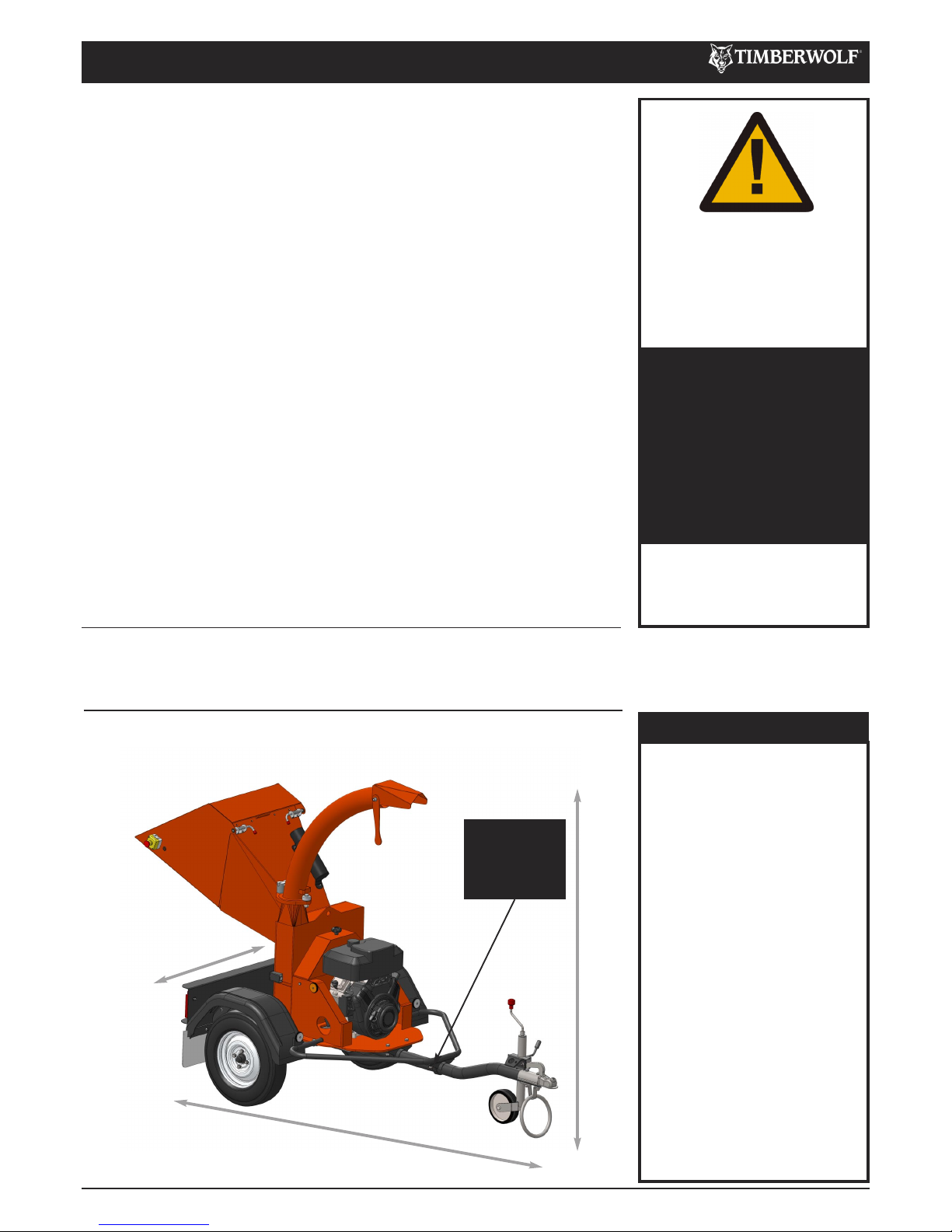
The Timberwolf TW 18/100G is designed to chip solid wood material up to 100mm
in diameter and capable of chipping over 1.5 tonnes of brushwood per hour.
PURPOSE
Engine type:
Briggs & Stratton V-Twin
(electric start)
Maximum power:
13.4kW (18hp)
Cooling method:
Air cooled
Overall weight:
385kg
Starting method:
Electric
Type of feed:
Gravity
Maximum diameter material:
100mm (4")
Fuel capacity:
8.5 litres
Material processing capacity:
1.5 tonnes/hr
Fuel type:
Unleaded petrol
DIMENSIONS
TW 18/100G
2 /37
INTRODUCTION
C190-0191 01.03.2019 Rev: 2.0
Thank you for choosing Timberwolf. Timberwolf chippers are designed to give safe
and dependable service if operated according to the instructions.
IMPORTANT HEALTH AND SAFETY INFORMATION
Before using your new chipper, please take time to read this manual. Failure to do
so could result in:
- personal injury
- equipment damage
- damage to property
- 3rd party injuries
This manual covers the operation and maintenance of the Timberwolf
TW 18/100G. All information in this manual is based on the latest product
information available at the time of purchase.
All the information you need to operate the machine safely and effectively is
contained within pages 3 to 11. Ensure that all operators are properly trained for
operating this machine, especially in safe working practices.
Timberwolf's policy of regularly reviewing and improving their products may involve
major or minor changes to the chippers or their accessories. Timberwolf reserves
the right to make changes at any time without notice and without incurring any
obligation.
Due to improvements in design and performance during production there may be,
in some cases, minor discrepancies between the actual chipper and the text in this
manual.
The manual should be considered an important part of the machine and should
remain with it if the machine is resold.
CAUTION or WARNING
BE AWARE OF THIS SYMBOL
AND WHERE SHOWN,
CAREFULLY FOLLOW THE
INSTRUCTIONS.
THIS SYMBOL INDICATES
IMPORTANT SAFETY
MESSAGES IN THIS MANUAL.
WHEN YOU SEE THIS
SYMBOL, BE ALERT TO THE
POSSIBILITY OF INJURY TO
YOURSELF OR OTHERS AND
CAREFULLY READ THE
MESSAGE THAT FOLLOWS.
ALWAYS FOLLOW SAFE
OPERATING AND
MAINTENANCE PRACTICES
TW 18/100G SPECIFICATION
Serial No. Location.
The serial number
can be found on
the identification
plate located on
the chassis beam.
2065mm (1570mm with discharge removed)
2910mm (2560mm with feed tray closed)
1280mm
Page 5

TW 18/100G
3 /37
PARTS LOCATOR
C190-0191 01.03.2019 Rev: 2.0
FUNNEL
DISCHARGE BUCKET
TOP ROTOR
HOUSING GUARD
BELT GUARD
TOW HEAD
JOCKEY
WHEEL
ASSEMBLY
DISCHARGE TUBE
DISCHARGE CLAMPS
DRAW BAR
CONTROL PANEL
FUEL TANK
EXHAUST
SKID PLATE RESTRAINING CABLE
ANTI-TRAP BAR
RAIN FLAP
REFLECTORS
THE TW 18/100G HAS THE FOLLOWING FIXED GUARDS FOR PROTECTION OF THE OPERATOR, CHIPPER
AND ENVIRONMENT:
Funnel: Protects the user from injuries from moving parts and ejected material during operation. •
Top Rotor Housing Guard: Protects user from rotational parts e.g. cutting blades. The interlocking switch disengages •
the engine when the hatch is opened to stop the chipper running.
Belt Guard: Protects the user from rotational parts e.g. belts and pulleys, hot surfaces and engine fluids. Protects •
machine from ingress of environmental debris.
Guards may be removed for maintenance only, as described in the Service Instruction pages of this manual. Ensure guards
remain in place throughout operation.
EMERGENCY STOP
MANUAL
CANNISTER
Page 6
TW 18/100G
4 /37
PARTS LOCATOR
C190-0191 01.03.2019 Rev: 2.0
ROTOR
FAN SECTION (x 2)
CUTTER BLADES
ENGINE DRIVE PULLEY
DRIVE BELTS
ROTOR DRIVE PULLEY
DRIVE BELT
TENSIONER PULLEY
BATTERY COMPARTMENT
TOOL BOX CONTENTS:
Copper Ease •
Lock Unit Keys x 2 •
Ignition Keys x 2 •
Combination Spanner (17mm/19mm) •
Blade bolts •
Star (torx) tip and driver•
FEED FUNNEL CURTAINS
FRONT BEARING HOUSING
BLADE ACCESS COVER
Page 7
5 /37
SAFE WORKING
C190-0191 01.03.2019 Rev: 2.0
TW 18/100G
WARNING
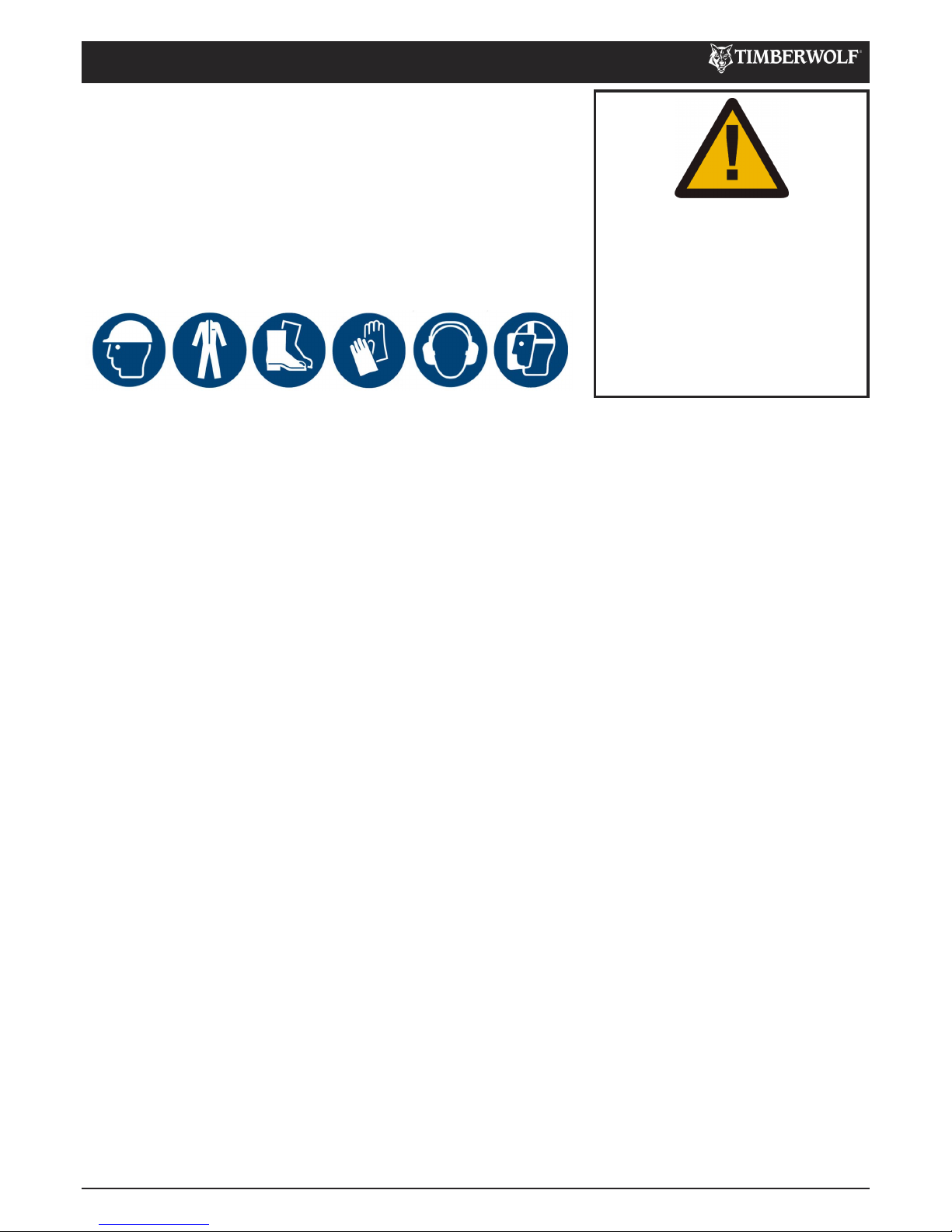
Chainsaw safety helmet (EN 397) fitted with mesh visor (EN 1731) and •
ear defenders (EN 352).
Work gloves with elasticated wrist. •
Steel toe cap safety boots (EN 345-1). •
Close fitting heavy-duty non-snag clothing. High-visability clothing (EN •
471) if risk assessment identifies the need.
Face mask if appropriate. •
DO NOT wear rings, bracelets, watches, jewellery or any other items that •
could be caught in the material and draw you into the chipper.
OPERATOR'S PERSONAL PROTECTIVE EQUIPMENT PPE
BASIC WOODCHIPPING SAFETY
GENERAL SAFETY MATTERS
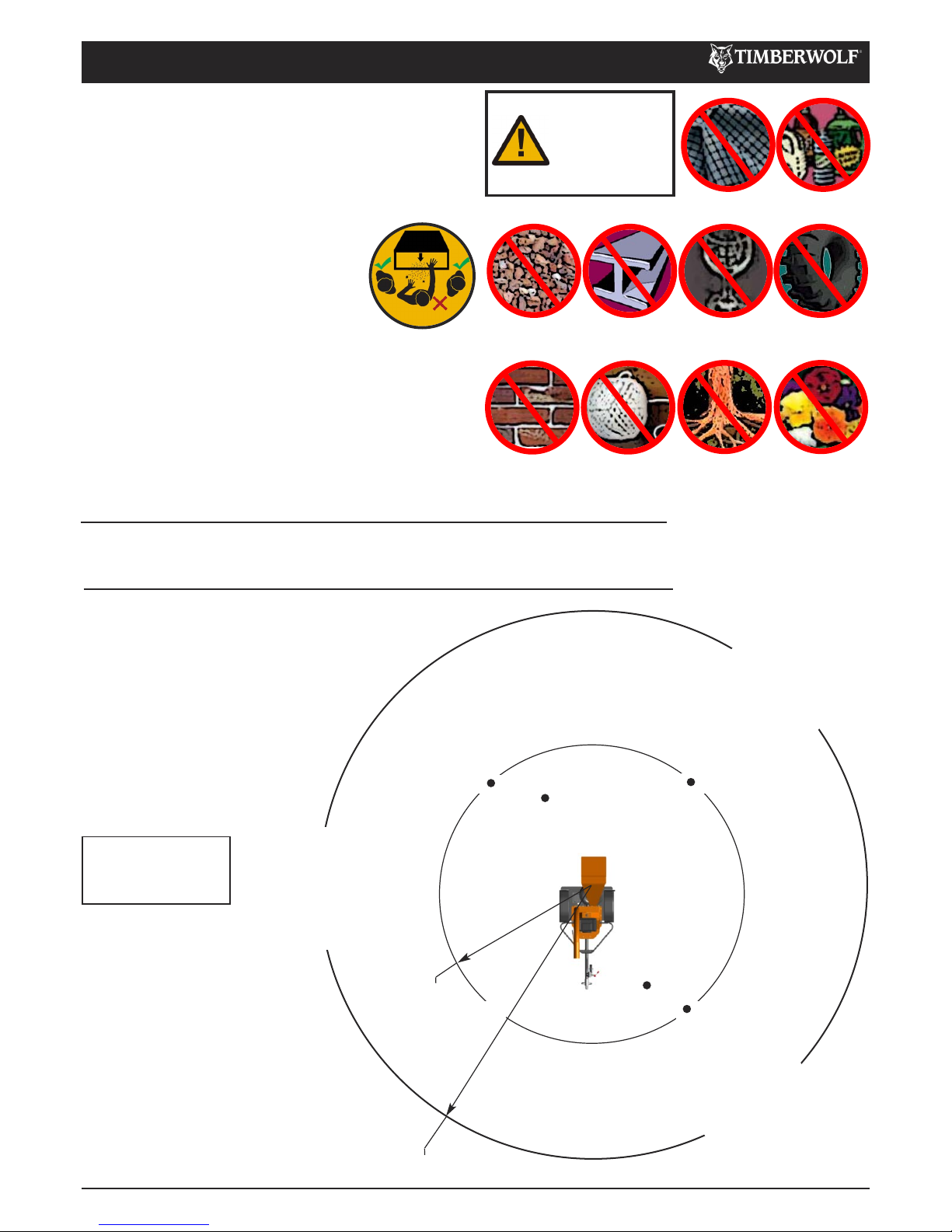
The chipper will feed material
through on its own. To do this, it
relies on sharp blades on the
chipper rotor. To keep the blades
sharp, only feed the machine with
clean brushwood. DO NOT put
muddy/dirty wood, roots, potted
plants, bricks, stones or metal into
the chipper.
The operator should be aware of the following points:
Maintain a safety exclusion zone around the chipper of at least 10 metres for the general public or employees without •
adequate protection. Use hazard tape to identify this working area and keep it clear from debris build up. Chips should
be ejected away from any area the general public have access to.
Hazardous material - Some species of trees and bushes are poisonous. The chipping action can produce vapour, spray •
and dust that can irritate the skin. This may lead to respiratory problems or even cause serious poisoning. Check the
material to be chipped before you start. Avoid confined spaces and use a face mask if necessary.
Be aware when the chipper is processing material that is an awkward shape. The material can move from side to side •
in the funnel with great force. If the material extends beyond the funnel, the brash may push you to one side causing
danger. Badly twisted brash should be trimmed before being chipped to avoid thrashing in the feed funnel.
Be aware that the chipper can eject chips out of the feed funnel with considerable force. Always wear full head and •
face protection.
Always work on the side of the machine furthest from any local danger, e.g. not road side. •
Never leave the chipper unattended when running. Machines must be supervised at all times when in use. •
In the event of an accident, stop the machine, remove the key and call the emergency services immediately.•
Always stop the chipper engine before making any adjustments, refuelling or cleaning. •
Always check the rotor has stopped rotating and remove the chipper ignition key before maintenance of any kind, or •
whenever the machine is to be left unattended. If in doubt, look through the in-feed funnel to see if rotor is still moving.
Always check the machine is well supported and cannot move. If working on an incline, position on solid ground, across •
the slope.
Always operate the chipper with the engine set to maximum speed when chipping. •
Always check (visually) for fluid leaks. If found, resolve the leak before operating the chipper. •
Always take regular breaks. Wearing personal protective equipment for long periods can be tiring and hot. •
Always keep hands, feet and clothing out of feed opening, discharge and moving parts. •
Always use a push stick to push in short pieces. Under no circumstances should you reach into the funnel. •
Always keep the operating area clear of people, animals and children. •
Always keep the operating area clear from debris build up. •
Always keep clear of the chip discharge tube. Foreign objects may be ejected with great force. •
Always ensure protective guarding is in place before commencing work. Failure to do so may result in personal injury •
or loss of life.
Always operate the chipper in a well ventilated area - exhaust fumes are dangerous. •
Ensure a fire extinguisher is available on site. •
Ensure a personal first aid kit and hand cleaning materials are available (e.g. waterless skin cleanser).•
Page 8
TW 18/100G
6 /37
SAFE WORKING
C190-0191 01.03.2019 Rev: 2.0
GENERAL SAFETY MATTERS
Do not operate chipper unless available light is •
sufficient to see clearly.
Do not use or attempt to start the chipper without the •
feed funnel, guards and discharge unit securely in
place.
Do not stand directly in front of the feed •
funnel when using the chipper. Stand to
one side.
Do not smoke when refuelling. •
Do not let anyone who has not received •
instruction operate the machine.
Do not climb on the machine at any time. •
Do not handle material that is partially engaged in the •
machine.
Do not touch any exposed wiring while the machine is •
running.
Do not use the chipper inside buildings.•
Noise levels above 80dB (A) will be
experienced at the working position.
Prolonged exposure to loud noise may cause
permanent hearing loss. All persons within a
4 metre radius must also wear good quality
ear protection (EN 352) at all times to
prevent possible damage to hearing.
Guaranteed Sound
Power: 125dB (A)
As required by Annex III of Directive
2000/14/EC “Noise Emission in the
environment by equipment for use outdoors”.
Tested according to BS EN ISO 3744:2010.
NOISE TEST
Machine: TW 18/100G
Notes: Tested chipping 50mm x 50mm corsican pine 1.5m in length
DO NOT ALLOW
THE FOLLOWING
TO ENTER THE
MACHINE, AS
DAMAGE IS
LIKELY
BRICKS STRING ROOTS BEDDING
PLANTS
STONES METAL GLASS RUBBER
CLOTH PLASTIC
91.2 dB
96.7 dB
101 dB
R= 4 metres
109.3 dB
R= 10 metres
9
5
d
B
C
a
l
c
u
l
a
t
e
d
9
5
d
B
C
a
l
c
u
l
a
t
e
d
9
5
d
B
C
a
l
c
u
l
a
t
e
d
95.5 dB
97.6 dB
Page 9

TW 18/100G
7 /37
SAFE WORKING
C190-0191 01.03.2019 Rev: 2.0
Check ball head is well greased. •
Wind jockey wheel assembly anticlockwise until the tow •
head is above the height of the ball hitch on the vehicle.
Reverse vehicle so the ball hitch is directly below •
the tow head.
Attach breakaway cable to a strong point on the vehicle, •
not the ball hitch.
Grasp handle on tow head and push back catch with •
thumb.
Wind jockey wheel assembly clockwise, to lower the •
tow head onto the ball hitch.
Release handle and continue to wind jockey wheel •
clockwise. The tow head should snap into place on the
ball hitch. If it doesn't, repeat previous 2 steps.
Wind jockey wheel up until fully retracted and the •
jockey wheel frame is seated in its notch on the stem.
The chipper weight should be fully on the vehicle.
Check jockey wheel handle is secure before •
transportation. Do not overtighten jockey wheel
handle.
Release jockey wheel clamp and slide the jockey •
wheel assembly fully up.
Tighten clamp on jockey wheel assembly. •
Connect electrical plug to socket on rear of towing •
vehicle and check operation of all the trailer and vehicle
lights.
The chipper is now properly attached to the vehicle.•
SAFE TRANSPORTATION
HITCHING ONTO THE TOW BALL
UNHITCHING THE CHIPPER
Ensure the chipper will not roll away after being •
disconnected from the vehicle.
Disconnect the electrical cable from the vehicle socket •
and stow in the dock provided on the chassis when not
in use.
Release breakaway cable and stow in the dock provided •
on the chassis when not in use.
Release the jockey wheel assembly clamp. •
Lower the jockey wheel assembly fully. •
Retighten the jockey wheel assembly clamp. •
Wind the jockey wheel assembly anticlockwise until it •
starts to take the weight of the chipper.
Grasp the handle and release the catch with your •
thumb.
Continue to wind the jockey wheel anticlockwise. This •
should lift the tow head clear of the ball hitch.
Drive the vehicle clear of the chipper. •
Wind the jockey wheel assembly to a suitable point •
where the chipper is level. Do not overtighten jockey
wheel handle.
The chipper is now fully detached from the vehicle.•
When towing a chipper the maximum speed limit is 60 •
mph.
On rough or bumpy road surfaces reduce speed •
accordingly to protect your machine from unnecessary
vibration.
When towing off road be aware of objects that may •
catch the chipper undergear.
When towing off road ensure inclination is not •
excessive.
Avoid excessively pot holed ground. •
When reversing the chipper the short wheel base will •
react quickly to steering.
Always check the discharge is tight before moving. •
Keep tyre pressures •
inflated to 1.8 bar or 26
psi.
Check wheel nuts are •
tightened to 90nm or 65
lbs ft.
Clear loose chippings and debris from the machine •
before departing.
Ensure feed funnel is closed and the catch is properly •
engaged before departing.
NEVER transport any items in feed funnel. •
Ensure tow hitch lock mechanism is locked before •
transporting.
WARNING
DO NOT RIDE ON
THE CHIPPER
WHEN IT IS
BEING TOWED.
Page 10

TW 18/100G
8 /37
STORAGE
C190-0191 01.03.2019 Rev: 2.0
STORING THE CHIPPER
Perform the following tasks at the storage intervals indicated, following procedures described within this manual.
Storage time
Maintenance Tasks
<1
month
1-6
months
6-12
months
>12
months
Allow the engine to cool down.
ü ü ü ü
Clean the chipper, removing all woodchips.
ü ü ü ü
Perform routine maintenance.
ü ü ü ü
Check all fasteners and retighten.
ü ü ü ü
Remove all fuel from the tank. NOTE: Either allow the machine to run until all fuel has been
used, or drain from the plug provided. If necessary, siphon the fuel into an approved storage
container (refer to re-fuelling section). Drain prior to moving machinery, to prevent spillage.
ü ü ü ü
Disassemble the spark plug (petrol machines).
ü ü ü ü
Where paint is damaged, touch up paint or treat with a lubricant. NOTE: Original paint colours
are available from Timberwolf dealers.
ü ü ü ü
Store the chipper in a dry place at +5°C to +40°C. NOTE: Timberwolf strongly recommends the
machine is stored in a sheltered location, protected from rain. If the machine is stored outside,
it must be well protected with tarpaulin.
x
ü ü ü
If relative humidity of the storage environment is > 60%, the shaft of the engine must be
rotated by hand 1-2 revolutions bi-weekly. Prior to rotating the shaft, 20 to 30 ml of engine oil
should be poured onto the bearing liner.
x
ü ü ü
Every 3 months, inspect the machine as per <1 month column.
x x
ü ü
Clean out and drain all lubrication lines, including grease pipes, fuel lines, oil reservoirs.
Replace with new lubricants. NOTE: This should be performed at 6 month intervals (months 6
& 12) until re-commissioned. Drain prior to moving machinery, to prevent spillage.
x x
ü ü
Release and reapply handbrake to confirm it has not become sticky or faulty.
x x
ü ü
Check and restore tyre pressure levels.
x x
ü ü
Keep machine in original container/packaging or equivalent protection and store in a location
free from extremes in temperature, at a min. temp. of +5°C and max. +40°C, humidity and
corrosive environments. NOTE: If the storage location is cold, damp or severe humidity changes
exist, adequate action should be taken to safeguard machinery.
x x x
ü
If machine is exposed to environmental conditions such as humidity during storage, inspect
bearing lubrication system for presence of water. If water is detected in the lubricant, flush out
the bearing housing and re-lubricate immediately.
x x x
ü
All breathers and drains are to be operable while in storage and/or the moisture drain plugs
removed. The machinery must be stored so the drain(s) are at the lowest point, while the
machine is in its stable position.
x x x
ü
Follow the recommissioning process before operation.
x
ü ü ü
NOTE:
Regardless of storage time, all Timberwolf machines must be in a stable, level position when unhitched from a vehicle.
Lower the Jockey wheel, unhitch and lower the prop stand, to ensure the machine is unable to roll or move unintentionally
during storage. The discharge tube must be pointing towards the tow head. Braked machines should have the brake applied.
Page 11
TW 18/100G
9 /37
OPERATING INSTRUCTIONS
C190-0191 01.03.2019 Rev: 2.0
RECOMMISSIONING AFTER STORAGE
Ensure machine is stable. •
Remove all guards and check all fasteners. If necessary, •
retighten as described within this manual.
Ensure discharge tube is correctly fastened, free of •
objects or blockages and rotates around its pivot
without being directed to face the point of operation
(danger zone).
Ensure feed funnel is free from foreign objects e.g. tools •
and clothing.
Lower and raise feed funnel into its open and closed •
positions to confirm functionality.
Check fuel within engine and top up accordingly. * •
Inspect all internal parts e.g. drive belts, taper locks and •
shaft keyways.
Check belt tension as described within this manual. •
Inspect cutting blades to confirm they are sharp and •
suitable for use.
Re-connect the battery to its positive and negative •
terminals.
Undertake electrical diagnostic continuity check, to •
confirm circuit is complete.
Check tyre pressures. •
Re-lubricate all grease pipes. Remove pipes and bleed •
the system prior to use, if necessary. *
Follow daily checks before starting, as described within •
this manual.
Start the machine. •
Run for 15 minutes at half throttle, prior to any cutting •
activity, to clear the combustion engine. Once complete,
bring the machine onto full throttle for a further 5
minutes.
*Storage fluids should be replaced, DO NOT USE old
stagnate fluids.
DELIVERY
All Timberwolf TW 18/100G machines have a full pre - delivery inspection before leaving the factory and are ready to use.
Read and understand this instruction manual before attempting to operate the chipper. In particular, read pages 5-7 which
contain important health and safety information and advice.
For more detailed information refer to the Engine Owner’s Manual
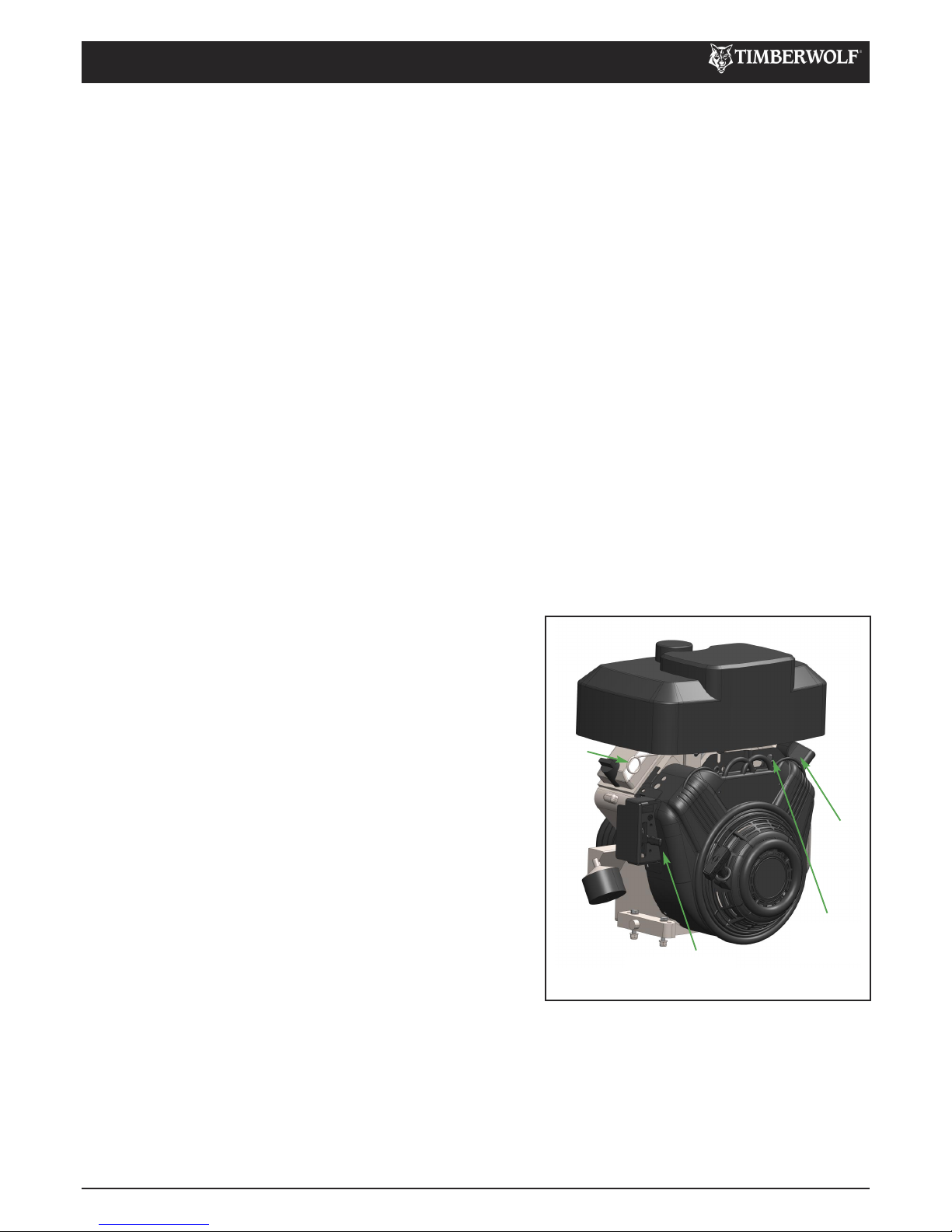
The engine speed is controlled by the vertically adjustable lever shown in diagram below. With the throttle lever in the
FAST position the machine is ready to chip. It MUST be pushed up as far as possible to achieve a suitable working speed.
If no wood is to be chipped for a few minutes the throttle should be returned to the idle position.
ENGINE CONTROLS
Open fuel shutoff valve. •
Pull choke control to the full choke position. •
Move throttle lever to ‘fast’. Always operate engine with throttle •
set to ‘fast’.
Push ‘on/off’ rocker switch to ‘on’ position. •
Insert key in ignition and turn to start engine. •
Release key as soon as engine starts. •
NOTE: To extend the life of the starter use only short starting •
cycles - 5 seconds max.
Allow engine to warm up. •
In cold weather, allow engine to run smoothly before each •
change in the position of the choke handle. Operate with choke
in ‘run’ position.
In warm weather temperatures or recently operated conditions, •
move choke handle slowly in towards the ‘run’ position.
THROTTLE LEVER
CHOKE
FUEL
SHUTOFF
VALVE
IGNITION
SWITCH
STARTING THE ENGINE
STOPPING THE ENGINE
Move throttle lever to ‘slow’ •
Turn ignition key to ‘off’ position and remove. •
Close fuel shutoff valve.•
EMERGENCY STOPPING
Should the machine need to be stopped in an emergency, push the red emergency stop button positioned on the funnel.
This stops all power to the engine, bringing the machine to a complete stop. The engine cannot be restarted until the
button is restored to its original position and the main ignition switch is turned off to reset the machine. Before disengaging
the emergency stop button, ensure the engine has come to a complete standstill then inspect the machinery to determine
the reason for activation.
Page 12
TW 18/100G
10 /37
OPERATING INSTRUCTIONS
C190-0191 01.03.2019 Rev: 2.0
Check that the chipper is running smoothly. •
Stand to one side of the feed funnel. •
Proceed to feed material into the feed funnel. •
STARTING TO CHIP
WARNING
DO NOT USE OR
ATTEMPT TO START THE
CHIPPER WITHOUT THE
PROTECTIVE GUARDING
AND DISCHARGE UNIT
SECURELY IN PLACE.
FAILURE TO DO SO MAY
RESULT IN PERSONAL
INJURY OR LOSS OF LIFE.
ROTATION
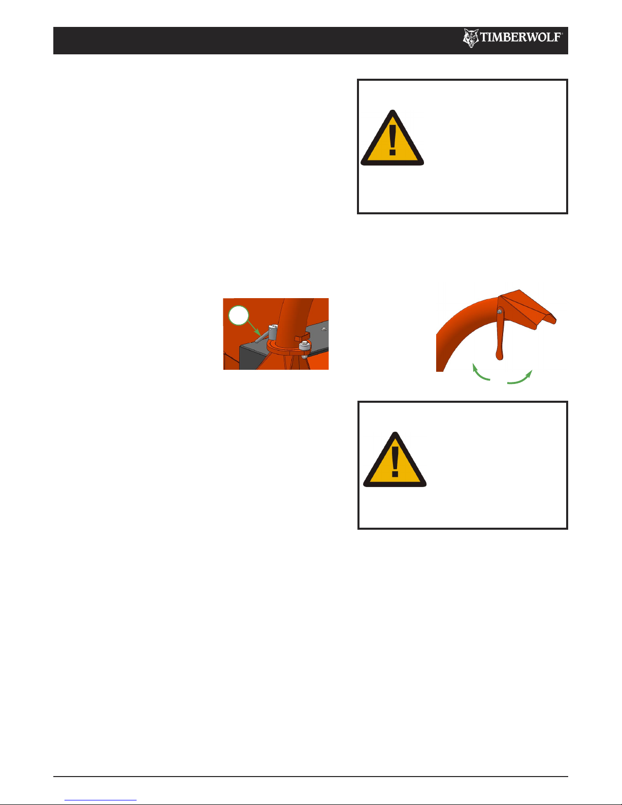
Slacken nut using integral handle. 1
Rotate tube. 2
Retighten nut.3
1
DISCHARGE CONTROLS
Controlling the discharge is an essential part of safe working.
BUCKET ANGLE
Adjust the bucket to
the desired angle
using the handle
provided.
Locate the machine on firm level ground. •
Check machine is well supported and cannot move. •
Check all guards are fitted and secure. •
Check the discharge unit is in place and fastened securely. •
Check discharge tube is pointing in a safe direction. •
Check the feed funnel to ensure no objects are inside. •
Check feed table is in up position - to prevent people reaching •
cutting blades.
Check controls as described. •
Check (visually) for fluid leaks. •
Check fuel levels. •
For parts location see diagrams on pages 3 & 4.
DAILY CHECKS BEFORE STARTING
WARNING
DO NOT USE OR
ATTEMPT TO START THE
CHIPPER WITHOUT THE
PROTECTIVE GUARDING
AND DISCHARGE UNIT
SECURELY IN PLACE.
FAILURE TO DO SO MAY
RESULT IN PERSONAL
INJURY OR LOSS OF LIFE.
CHIPPING
Wood up to the recommended diameter can be fed into the feed
funnel. Enter it into the funnel butt end first. Release the material
before it engages the rotor. Some pieces of wood may move around
significantly while being chipped.
The wood will be drawn into the cutting blade quite quickly, be ready
for this to happen. Stand well clear.
A piece of wood which is too tough or too large for the chipper will
slow the engine down. When this happens it is possible to hold back
the branches that are being chipped and allow the engine to regain its
speed again.
If a piece of wood gets stuck in the funnel and it cannot be chipped
due to its size or shape, it will need to be removed. Stop the engine
and wait for moving parts to stop before removing the material. Trim
the branch until it is a suitable shape for the chipper to accept.
Page 13
TW 18/100G
11 /37
OPERATING INSTRUCTIONS
C190-0191 01.03.2019 Rev: 2.0
BLOCKAGES
Always be aware that what you are putting into the chipper must come
out. If the chips stop coming out of the discharge tube but the chipper
is taking material in - STOP IMMEDIATELY. Continuing to feed material
into a blocked machine may cause damage and will make it difficult to
clear. If the chipper becomes blocked, proceed as follows:
Stop the engine and remove the spark plug lead. •
Remove the discharge tube. Check that it is clear. •
Wearing gloves, reach into the rotor housing and scoop out the •
majority of the debris causing the blockage.
Replace the discharge tube. •
Restart the engine and increase to full speed. •
Allow machine time to clear excess chips still remaining in rotor housing before you continue feeding brushwood. •
Feed in a small piece of wood while watching to make sure that it comes out of the discharge. •
If this does not clear it, repeat the process and carefully inspect the discharge tube to find any obstruction. •
NOTE
Continuing to feed the chipper with brushwood once it has become blocked will cause the chipper to compact the chips
in the rotor housing and it will be difficult and time consuming to clear.
AVOID THIS SITUATION - WATCH THE DISCHARGE TUBE AT ALL TIMES.
WARNING
DO NOT REACH INTO THE
ROTOR HOUSING WITH
UNPROTECTED HANDS.
THERE ARE SHARP
BLADES AND ANY SMALL
MOVEMENT OF THE
ROTOR MAY CAUSE
SERIOUS INJURY.
BLADE WEAR
The most important part of using a wood chipper is keeping the cutter blades sharp. Timberwolf chipper blades are hollow
ground to an angle of 40 degrees. When performing daily blade checks ensure blade edge is sharp and free from chips, if
there is any evidence of damage, or the edge is “dull” change the blade(s). The TW 18/100G is fitted with 2 blades 177mm
(7") long. They are 44 mm wide when new. A new blade should chip for up to 25 hours before it requires sharpening.
This figure will be drastically reduced by feeding the machine with stony, sandy or muddy material.
As the blade becomes blunt, performance is reduced. With increased stress and load on the machine the chips will become
more irregular and stringy. At this point the blade should be sent to a reputable blade sharpening company. The blade
can be sharpened several times in its life. A wear mark indicates the safe limit of blade wear. Replace when this line is
exceeded.
The machine is also fitted with a static blade (anvil). It is important that the anvil is in good condition to allow the cutting
blades to function efficiently. Performance will be poor even with sharp cutter blades if the anvil is worn.
REFUELLING
When refuelling, follow standard Health & Safety practices:
Stop the engine and allow to cool before refuelling. •
Never smoke or allow naked flames nearby while refuelling. •
Store fuel away from vapour ignition sources such as fires and people smoking. •
Never refuel at operating location, keep a distance of > 10 m to avoid creating fire hazards. •
Fuel storage containers must be approved for diesel fuel storage and clearly labelled with securely fitting caps. •
Clean area around fuel cap and use a funnel for refuelling. Replace the fuel cap securely. Do not fill the tank beyond •
the max. fill indicator.
Avoid skin contact with fuel. If it gets into eyes wash out with sterile water immediately and seek medical advice as •
soon as possible.
Always clean spillages quickly and change clothes before re-entering the work area if fuel is spilled onto garments.•
FUEL LEVEL INDICATOR
The fuel level can be seen through the wall of the plastic tank.
Page 14

TW 18/100G
12 /37
OPERATING INSTRUCTIONS
C190-0191 01.03.2019 Rev: 2.0
THE FOLLOWING PAGES DETAIL ONLY BASIC
MAINTENANCE GUIDELINES SPECIFIC TO YOUR CHIPPER.
THIS IS NOT A WORKSHOP MANUAL.
The following guidelines are not exhaustive and do not extend to generally accepted standards of
engineering/mechanical maintenance that should be applied to any piece of mechanical equipment and the chassis
to which it is mounted.
Authorised Timberwolf service agents are fully trained in all aspects of total service and maintenance of Timberwolf
wood chippers. You are strongly advised to take your chipper to an authorised agent for all but the most routine
maintenance and checks.
Timberwolf accepts no responsibility for the failure of the owner/user of Timberwolf chippers to recognise generally
accepted standards of engineering/mechanical maintenance and apply them throughout the machine.
The failure to apply generally accepted standards of maintenance, or the performance of inappropriate maintenance
or modifications, may invalidate warranty and/or regulatory compliance, in whole or in part.
Please refer to your authorised Timberwolf service agent for service and maintenance.
TROUBLESHOOTING
This table is a troubleshooting guide to common problems.
If your problem is not listed below, or is unresolved after following the guide, please contact your Timberwolf service agent,
whose Timberwolf trained engineers can perform further fault finding. Before you call, please have this operating manual
and the machine serial number ready.
Problem Cause Solution Caution - Always ensure appropriate PPE is worn.
Wood chip
ejection
stopped /
limited
Obstructed
discharge
Clear debris from discharge chute.
Ensure machine is off and keys
removed.
Loose drive belts Refer to manual & tension belts guidelines.
Ensure machine is off and keys
removed.
Broken rotor
paddles
Inspect paddles, replace broken / missing
paddle.
Ensure machine is off and keys
removed. Call engineer for repair.
Rotor does
not turn
Obstructed
discharge
Clear debris from discharge chute.
Ensure machine is off and keys
removed.
Rotor jammed
Inspect & clear infeed funnel and rotor
housing.
Ensure machine is off and keys
removed.
Drive belt issue
Inspect drive belts, replace if required.
Refer to manual & tension belts guidelines.
Ensure machine is off and keys
removed.
Slow or not
feeding
Low engine speed
Check & inspect throttle and cable. Check
throttle is set to specified speed.
Ensure machine is off and keys
removed.
Blades dull Rotate, sharpen or replace blades.
Ensure machine is off and keys
removed.
Anvils dull
Check anvil has sharp edge, rotate, sharpen
or replace if necessary.
Ensure machine is off and keys
removed.
Obstructed
discharge
Clear debris from discharge chute.
Ensure machine is off and keys
removed.
Page 15

TW 18/100G
13 /37
SERVICE INSTRUCTIONS
C190-0191 01.03.2019 Rev: 2.0
SERVICE SCHEDULE
WARNING
ALWAYS IMMOBILISE THE MACHINE BY STOPPING THE ENGINE, REMOVING THE
IGNITION KEY AND DISCONNECTING THE BATTERY BEFORE UNDERTAKING ANY
MAINTENANCE WORK.
SERVICE SCHEDULE
Daily
Check
25
Hours
50
Hours
100
Hours
250
Hours
Check engine oil - top up if necessary (10W-30).
ü
Check fuel level.
ü
Check feed funnel, access cover, belt guard and
discharge unit are securely fitted.
ü
Check tyre pressure is 1.8 Bar (26 psi).
ü
Check funnel flange and front face.
ü
Check for tightness front and rear bearing retaining
nuts.
ü
Check for tightness spindle screw in centre of front
bearing.
ü
Check for tightness engine mount bolts.
ü
Check tension of main drive belts (and tension if
necessary).
ü
Clean air filter foam pre cleaner.
ü
Check machine to ensure nothing has worked loose.
ü
Change blades if necessary.
ü
Check wheel nuts are tight.
ü
Check all bolts retaining chipper to chassis.
ü
Repeat 25 hour service.
ü
Change oil.
ü
Check anvil for wear.
ü
Repeat 25 & 50 hour service.
ü
Replace oil filter.
ü
Inspect air filter - replace if necessary.
ü
Check battery electrolyte level .
ü
Repeat 25 & 50 hour service.
ü
Change spark plugs.
ü
Replace anvil when worn. RETURN TO DEALER FOR ANVIL CHANGE
Page 16

TW 18/100G
14 /37
SERVICE INSTRUCTIONS
C190-0191 01.03.2019 Rev: 2.0
SPARES
Only fit genuine Timberwolf replacement blades, screws and
chipper spares. Failure to do so will result in the invalidation of
the warranty and may result in damage to the chipper, personal
injury or even loss of life.
The battery is located under the funnel. 1
Remove the negative lead first and then the positive lead. 2
Clean, charge and/or top up the battery as required. 3
Refitting is the reverse of removal. Apply a smear of 4
petroleum jelly to the terminals to prevent corrosion.
SAFE LIFTING OF THE CHIPPER
The lifting eye is designed to lift the machine’s weight only. Do
not use hoist hook directly on the lifting eye, use a correctly rated
safety shackle. Inspect the lifting eye prior to each use - DO NOT
USE LIFTING EYE IF DAMAGED. Maximum lift weight is 850kg, as
indicated on the machine.
BATTERY REMOVAL AND MAINTENANCE
CHECK FITTINGS
The Timberwolf TW 18/100G is subject to large vibrations during the normal course of operation. Consequently there is
always a possibility that nuts and bolts will work themselves loose. It is important that periodic checks are made to ensure
the security of all fasteners. Fasteners should be tightened using a torque wrench to the required torque (see below).
Uncalibrated torque wrenches can be inaccurate by as much as 25%. It is therefore essential that a calibrated torque
wrench is used to achieve the tightening torques listed below.
WARNING
REFER TO THE BATTERY SAFETY
SECTION ON PAGE 16.
SAFE MAINTENANCE
WARNING
ALWAYS IMMOBILISE THE ENGINE BEFORE
UNDERTAKING ANY MAINTENANCE WORK
ON THE CHIPPER BY REMOVING THE
IGNITION KEY AND DISCONNECTING THE
BATTERY. ENSURE THE CHIPPER IS STABLE
BEFORE PERFORMING ANY
MAINTENANCE.
Handle blades with extreme caution to avoid injury. Gloves •
should always be worn when handling the cutter blades.
The drive belts should be connected while changing blades, •
as this will restrict sudden movement of the rotor.
The major components of this machine are heavy. Lifting •
equipment must be used for disassembly.
Clean machines are safer and easier to service. •
Avoid contact with hazardous materials.•
Size Pitch Head Torque Ib/ft Torque Nm
Blade Bolts M8 Standard T40 Torq 22 30
General M8 Standard 13 mm Hex 20 27
General M10 Standard 17 mm Hex 45 61
General M12 Standard 19 mm Hex 65 88
Page 17

TW 18/100G
15 /37
SERVICE INSTRUCTIONS
C190-0191 01.03.2019 Rev: 2.0
HAZARDOUS MATERIALS & END OF MACHINE LIFE
During Machine Life
The following hazardous materials are supplied within Timberwolf machines:
Engine oil •
Battery acid •
Diesel •
Copper Ease •
MATERIAL SAFETY DATA SHEETS FOR HAZARDOUS MATERIALS SUPPLIED WITHIN TIMBERWOLF
MACHINES ARE AVAILABLE ON REQUEST. REFER TO THESE FOR FIRST AID AND FIRE PROTECTION
MEASURES.
Always follow recommended procedures for safe handling, removal and disposal of hazardous materials. Safety precautions
should be taken when handling hazardous materials (use of oil-resistant gloves and safety glasses are recommended respiratory protection is not required). Avoid direct contact with the substance and store in a cool, well ventilated area
avoiding sources of ignition, strong oxidising agents and strong acids. Ensure hazardous spillages do not flow into the
ground or drainage system and ensure potential environmental damage is controlled safely, according to local laws.
End of Machine Life
Follow these guidelines using approved local waste and disposal agencies for recycled materials, according to applicable
Health, Safety and Environmental laws.
Position the machine within reach of all necessary lifting equipment. •
Use tools and PPE detailed within maintenance instructions. •
Remove all hazardous materials and battery and store safely before disposal. •
Disassemble the machine structure, referring to the maintenance instructions. Pay attention to parts with mechanical •
pressure or tension applied, including springs.
Separate items that continue to have a service life. •
Separate worn items into material groups and where possible, recycle using available agencies for recycled materials. •
Common types are:
If a part is not easily separated into different material groups, it must be added to “general discarded materials”. •
Do not burn discarded materials. •
Change the machinery records to show that the machine is out of service and discarded. Supply this serial number to •
Timberwolf to close their records.
Steel
Non-ferrous metals
Aluminium
Brass
Copper
Plastic materials
Rubber
Electrical and Electronic Components
Other materials that can be recycled
Other materials that cannot be recycled
Page 18

TW 18/100G
16 /37
SERVICE INSTRUCTIONS
C190-0191 01.03.2019 Rev: 2.0
BATTERY SAFETY INFORMATION
1. Storage and transport
Batteries are filled with acid. •
Always store and transport batteries upright and prevent •
from tilting so that no acid can escape.
Store in a cool and dry place. •
Do not remove the protective cap from the positive •
terminal.
Run a FIFO (first in-first out) warehouse management •
system.
2. Initial operation
The batteries are filled with acid at a density of 1.28g/ml •
during the manufacturing process and are ready for use.
Recharge in case of insufficient starting power (see no. 4). •
3. Installation in the vehicle and removal from the vehicle
Switch off the engine and all electrical equipment. •
When removing, disconnect the negative terminal first. •
Avoid short circuits caused by tools, for example. •
Remove any foreign body from the battery tray, and •
clamp battery tightly after installation.
Clean the terminals and clamps, and lubricate slightly •
with battery grease.
When installing, first connect the positive terminal, and •
check the terminal clamps for tight fit.
After having fitted the battery in the vehicle, remove the •
protective cap from the positive terminal, and place it on
the terminal of the replaced battery in order to prevent
short circuits and possible sparks.
Use parts from the replaced battery, such as the terminal •
covers, elbows, vent pipe connection and terminal
holders (where applicable); use available or supplied filler
caps.
Leave at least one vent open, otherwise there is a danger •
of explosion. This also applies when old batteries are
returned.
4. Charging
Remove the battery from the vehicle; disconnect the lead •
of the negative terminal first.
Ensure good ventilation. •
Use suitable direct current chargers only. •
Connect the positive terminal of the battery to the •
positive output of the charger. Connect the negative
terminal accordingly.
Switch on the charger only after the battery has been •
connected, and switch off the charger first after charging
has been completed.
Charging current-recommendation: 1/10 ampere of the •
battery capacity Ah.
Use a charger with a constant charging voltage of 14.4V •
for re-charging.
If the acid temperature rises above 55
o
Celsius, stop •
charging.
The battery is fully charged when the charging voltage •
has stopped rising for two hours.
5. Maintenance
Keep the battery clean and dry. •
Use a moist anti-static cloth only to wipe the battery, •
otherwise there is a danger of explosion.
Do not open the battery. •
Recharge in case of insufficient starting power (see no. 4). •
6. Jump Starting
Use the standardised jumper cable in compliance with •
DIN 72553 only, and follow the operating instructions.
Use batteries of the same •
nominal voltage only.
Switch off the engines of •
both vehicles.
First connect the two positive •
terminals (1) and (2), then
connect the negative
terminal of the charged battery (3) to a metal part (4) of
the vehicle requiring assistance away from the battery.
Start the engine of the vehicle providing assistance, then •
start the engine of the vehicle requiring assistance for a
maximum of 15 seconds.
Disconnect the cables in reverse sequence (4-3-2-1). •
7. Taking the battery out of service
Charge the battery; store in a cool place or in the vehicle •
with the negative terminal disconnected.
Check the battery state of charge at regular intervals, and •
correct by recharging when necessary (see no. 4).
(1)
(2)
(3)
(4)
12V
12V
For safety reasons, wear eye •
protection when handling a
battery.
Keep out of reach of children. •
Fires, sparks, naked flames •
and smoking are prohibited.
Avoid causing sparks when •
dealing with cables and
electrical equipment, and
beware of electrostatic
discharges.
Avoid short circuits. •
Explosion hazard:
A highly explosive •
oxyhydrogen gas mixture is
produced when batteries are
charged.
Corrosive hazard:
Battery acid is highly corrosive,
therefore:
Wear protective gloves and •
eye protection.
Do not tilt the battery, acid •
may escape from the vent
openings.
First aid:
Rinse off acid splashed in the •
eyes immediately for several
minutes with clear water!
Remove contact lenses if worn
and continue rinsing. Then
consult a doctor immediately.
Neutralise acid splashes on the •
skin or clothes immediately
with acid neutraliser (soda) or
soap suds, and rinse with
plenty of water.
If acid is swallowed, consult a •
doctor immediately.
Warning notes: The battery case
can become brittle, to avoid this:
Do not store batteries in direct •
sunlight.
Discharged batteries may •
freeze up, therefore store in an
area free from frost.
Disposal:
Dispose of old batteries at an •
authorised collection point.
The notes listed under item 1 •
are to be followed for
transport.
Never dispose of old batteries •
in household waste.
WARNING NOTES AND SAFETY REGULATIONS FOR FILLED LEADACID BATTERIES
Page 19

TW 18/100G
17 /37
SERVICE INSTRUCTIONS
C190-0191 01.03.2019 Rev: 2.0
Turn the chipper off and remove the spark plug lead. 1
Remove the feed funnel. 2
Remove blade access cover. 3
Insert M10 screw into rotor to stop it turning. 4
Using the Torx fitting provided loosen the blade screws. 5
Remove the blade carefully. 6
Before fitting a new blade ensure the seating surface on the rotor is 7
spotlessly clean. This is necessary to ensure the blade is always held
firm. Damage to the rotor may be caused if this is not checked.
Apply a small amount of copper grease to the blade screws. 8
Using a torque wrench tighten the blade screws to 29 Nm (22 lb/ft). 9
Remove the M10 screw securing the rotor. 10
Re-install blade access cover. 11
Re-install the feed funnel.12
CHANGE BLADES
WARNING
WEAR RIGGERS GLOVES FOR THE BLADE
CHANGING OPERATION.
WARNING
ALWAYS SHARPEN BLADES ON A REGULAR BASIS. FAILURE TO DO SO
WILL CAUSE THE MACHINE TO UNDER PERFORM AND WILL OVERLOAD
ENGINE AND BEARINGS CAUSING MACHINE BREAKDOWN. BLADES
MUST NOT BE SHARPENED BEYOND THE WEAR MARK SEE DIAGRAM.
FAILURE TO COMPLY WITH THIS COULD RESULT IN MACHINE DAMAGE,
INJURY OR LOSS OF LIFE.
WEAR MARK
4
5
TENSION DRIVE BELTS
NOTE:There will normally be a rapid drop in tension during run-in period for new belts. When new belts are fitted,
check the tension every 2 - 3 hours and adjust until the tension remains constant. Belt failures due to lack of correct
tensioning will not be covered under your Timberwolf warranty.
2
3
Remove the discharge tube. 1
Apply multipurpose grease to surface shown. 2
Refit discharge tube.3
ENGINE SERVICING
All engine servicing must be performed in accordance with the Engine
Manufacturer’s Handbook provided with the machine. Failure to adhere to
this may invalidate warranty and/or shorten engine life.
Remove belt guard. 1
Loosen bolt in centre of tensioner pulley with a 19 mm spanner 2
so that pulley is able to slide with minimal wobble.
Turn nut in end of tensioner pulley slider until correct belt tension is 3
achieved. For instructions on checking belt tension & correct belt
tension values, please refer to the Timberwolf V-Belt Tensioning Data
Table (pg 24).
Re-tighten bolt in centre of tensioner pulley. 4
Re-install belt guard. 5
Run machine and test, recheck belt tension. 6
NOTE: Slack drive belts will cause poor performance and belt / pulley wear.
2
GREASE THE DISCHARGE FLANGE
Page 20

TW 18/100G
18 /37
WARRANTY STATEMENT
C190-0191 01.03.2019 Rev: 2.0
TIMBERWOLF NONONSENSE WARRANTY
All new Timberwolf machines come with peace of mind built in. Our no-nonsense warranty is your guarantee of your
Timberwolf wood chipper not letting you down.
Your warranty statement is included in your manual pack. Please ensure you register your machine with your dealer to
ensure you are eligible for the full Timberwolf warranty period.
Page 21

TW 18/100G
19 /37
DECLARATION OF CONFORMITY
C190-0191 01.03.2019 Rev: 2.0
Page 22

TW 18/100G
20 /37
IDENTIFICATION PLATE
C190-0191 01.03.2019 Rev: 2.0
EXAMPLE
Page 23

TW 18/100G
21 /37
DECALS
C190-0191 01.03.2019 Rev: 2.0
Warning.
Hot exhaust.
New drive belts need re-
tensioning.
When new belts are fitted check
tension every 2-3 hours & adjust
until tension remains constant.
Warning.
High velocity discharge -
keep clear.
Lifting eye is designed to lift the
machine’s weight only. Do not
use hoist hook directly on lifting
eye. Use correctly rated safety
shackle only through lifting eye.
Lifting eye to be inspected every
6 months or before each use.
Always visually inspect lifting eye
prior to each use. Do not use
lifting eye if damaged.
Caution.
Avoid standingdirectly in
front of feed funnel to
reduce exposure to noise,
dust and risk from ejected
particles.
Clean under blades before
refitting or turning. Failure to do
so may result in blade(s) coming
loose and damage being caused
to the rotor housing.
The instruction manual with
this machine contains
important operating,
maintenance and health and
safety information. Failure
to follow the information
contained in the instruction
manual may lead to death or
serious injury.
Danger.
Do not operate without this cover
in place.
Danger.
Rotating blades.
Keep hands and feet out.
Personal Protective Equipment
required.
See Page 5.
Decal Descripon
Decal Descripon
616
617
655
1662
4099
18393
2949
3022
P637 x 3
670
Page 24

TW 18/100G
22 /37
DECALS
C190-0191 01.03.2019 Rev: 2.0
Danger.
Do not use this machine without
the discharge unit fitted. failure
to comply may result in serious
inury or damage.
Danger.
Rotating blades inside.
Stop engine and remove key
before removing discharge unit.
Caution.
Do not put road sweepings in
machine as grit will damage
blades.
Caution.
When transporting, discharge
clamps may work loose.Check
frequently.
Fuel Here.
Risk of fire. Allow engine to cool
for 1 minute before refuelling.
Use unleaded petrol.
Do not climb into the funnel.
P652
P653
P654
Decal Descripon
Decal Descripon
8
5
0
K
G
M
A
X
dB
L
WA
dB
L
Aeq
TIMBERWOLF
TW 18/100G
1363 3012 3013 1849
17862 x 2 P*154
P656
P651
125
95
C192-0102
Page 25

TW 18/100G
23 /37
CIRCUIT DIAGRAM
C190-0191 01.03.2019 Rev: 2.0
5
21
3
4
2
RLY-001
ENG KILL RELAY 1
1413
GND
21 22
ROTOR_HSG
4 Pin NONC Switch
1
3
5
6
5
1
IGNITION +
C009
FROM BRIGGS IGNITION SW
W-1. 0
Fuse
ENG KILL RELAY 2
1
RLY-003
5
4
21
3
1
Solenoid
Starter Motor
B+
1
2
3
4
5
RLY-002
START INHIBIT RELAY
1
Removed from Start Sol
Start Sig
C005
U-1.0
B-1.0
GND GND GND
B-1.0
B-1.0
B-1.0
GND
12
B-R-1.0
B-R-1.0
B-R-1.0
B-R-1.0
F-001
Y-2 . 0
Y-1 . 0
B-1.0
B-W-1.0
W-B-1 .0
B-S-1.0
U-W-1.0
W-U- 1.0
Engine GNDC010
B-1.0
1
2
COIL-002
Ignition Coil
4
6
1
3
2
SW-001
E STOP
4
1
2
SW-005
E STOP
U-Y-1.0
B-R-1.0
U-K-1.0
B-1.0
B-1.0
D-001
Diode
W-R-1 .0
SP-003
U-W-1.0
U-W-1.0
W-R-2 .0
Fit to White Wire from Briggs Ign
M
Page 26

TW 18/100G
24 /37
V-BELT TENSIONING TABLE
C190-0191 01.03.2019 Rev: 2.0
Method:
Set the deflection distance on the lower scale of the tension gauge so that the underside of the 'o'-ring equals the 1
'h' value given in the table.
Ensure that the deflection force scale is zero'd by pushing the upper 'o'-ring all the way down. 2
Place the tension gauge in the centre of the belt span as shown in the diagram. 3
Press downwards on the rubber buffer, deflecting the belt until the underside of the lower 'o'-ring is level with the 4
belt behind (use a straight edge if there is only 1 belt).
Take the reading from the deflection scale of the tension meter (read at the lower edge of the 'o'-ring) & 5
compare this value with that given in the table.
Tighten or loosen belts as required following procedure given in this operator's manual. 6
Tension gauges are available from Timberwolf spares, quoting part no. 18091
Rotor Pulley
Engine Pulley
Belt Tensioner
Tips on belt tightening:
There will normally be a rapid drop in tension during •
the run-in period for new belts. When new belts are
fitted, check the tension every 2-3 hours & adjust until
the tension remains constant.
The best tension for V-belt drives is the lowest tension •
at which the belts do not slip or ratchet under the
highest load condition.
Too much tension shortens belt & bearing life. •
Too little tension will affect the performance of your •
machine especially in respect of no-stress devices.
Ensure that belt drives are kept free of any foreign •
materials.
If a belt slips - tighten it! •
TW 18/100G Rotor Belts
Belt Mffr / Type Gates Super HC-MN
Belt Pitch Designaon SPA
Belt Length in mm 1060
Belt Deflecon in mm = h 2.1
Force Reading (Kg)
New belt 1.3
Used Belt 1.1-1.2
Page 27

25 /37
WARRANTY SERVICE RECORD CHECK
C190-0191 01.03.2019 Rev: 2.0
TW 18/100G
Model number: Serial number:
Date of delivery/
handover:
Opons/extras:
Dealer pre
delivery check:
Inspected by:
Date:
Hours:
Invoice number:
Signature:
Next service due:
Authorised dealer stamp
50 HOUR WARRANTY SERVICE CHECK
Date:
Hours:
Invoice number:
Signature:
Next service due:
Authorised dealer stamp
11 MONTH WARRANTY SERVICE CHECK
Date:
Hours:
Invoice number:
Signature:
Next service due:
Authorised dealer stamp
23 MONTH WARRANTY SERVICE CHECK
Page 28

26 /37
SERVICE RECORD
C190-0191 01.03.2019 Rev: 2.0
TW 18/100G
Date:
Hours:
Invoice number:
Signature:
Next service due:
Authorised dealer stamp
Date:
Hours:
Invoice number:
Signature:
Next service due:
Authorised dealer stamp
Date:
Hours:
Invoice number:
Signature:
Next service due:
Authorised dealer stamp
Date:
Hours:
Invoice number:
Signature:
Next service due:
Authorised dealer stamp
Page 29

C190-0191 01.03.2019 Rev: 2.0
PARTS LIST
TW 230DHB
THE FOLLOWING ILLUSTRATIONS ARE FOR PARTS IDENTIFICATION ONLY. THE REMOVAL OR FITTING OF
THESE PARTS MAY CAUSE A HAZARD AND SHOULD ONLY BE CARRIED OUT BY TRAINED PERSONNEL.
PARTS LISTS
Page No.
BELT TENSIONER 28
CHASSIS 29
CHASSIS - DRAWBAR 30
DISCHARGE 31
ENGINE 32
FUNNEL & GUARDS 33
ROTOR 34
ROTOR HOUSING 35
DECALS 36
27 / 37
Page 30

TW 18/100G
28 / 37
C190‐0190 09.08.2018 Rev: 1.0
Page 31

29 / 37
C190‐0190 09.08.2018 Rev: 1.0
TW 18/100G
Page 32

TW 18/100G
30 / 37
C190‐0190 09.08.2018 Rev: 1.0
Page 33

31 / 37
C190‐0190 09.08.2018 Rev: 1.0
TW 18/100G
Page 34

32 / 37
C190‐0190 09.08.2018 Rev: 1.0
TW 18/100G
Page 35

33 / 37
C190‐0190 09.08.2018 Rev: 1.0
TW 18/100G
Page 36

34 / 37
C190‐0190 09.08.2018 Rev: 1.0
TW 18/100G
Page 37

35 / 37
C190‐0190 09.08.2018 Rev: 1.0
TW 18/100G
Page 38

C190‐0190 09.08.2018 Rev: 1.0
TW 18/100G
670
3013
1662
P*637
P*656
P*653
P*655
P*652
P*654
8
5
0
K
G
M
A
X
2949
18393
617
606
P651
36 / 37
dB
L
WA
dB
L
Aeq
125
95
3012
1849
17862
Page 39

37 / 37
C190‐0190 09.08.2018 Rev: 1.0
TW 18/100G
4099
3022
TIMBERWOLF
TW 18/100G
C192‐0102
P637
P637
1363
P154
Page 40

Page 41

timberwolf-uk.com
Timberwolf Ltd Wood Chippers & Shredders
Tomo Industrial Estate, Stowmarket, Suffolk IP14 5AY, United Kingdom
T: +44 1449 765800 E: info@timberwolf-uk.com W: timberwolf-uk.com
 Loading...