

Page 1

INSTALLER: LEAVE THIS MANUAL WITH THE APPLIANCE.
CONSUMER: RETAIN THIS MANUAL FOR FUTURE REFERENCE.
INSTALLATION AND
OPERATING INSTRUCTIONS
This appliance has been tested to ASTM E 1509, ULC/ORD C1482M-90, ULC S627 AND ULC S628.
TPS35
PELLET STOVE
TPI35
1
PELLET INSERT
CERTIFIED FOR CANADA AND UNITED STATES USING ANSI/CSA METHODS.
SAFETY INFORMATION
!
WARNING
PLEASE READ ENTIRE MANUAL
BEFORE YOU INSTALL OR USE THIS
PELLET BURNING APPLIANCE.
If the appliance is not properly installed,
a house fi re may result causing personal
injury or loss of life.
- Authorities having jurisdiction (such as
municipal building department, fi re department,
fi re prevention bureau, etc.) should be consulted
before installation to determine the need to obtain
a permit.
- Contact local building or fi re offi cials about
restrictions and installation inspection
requirements in your area.
- This appliance is hot while in operation. Keep
children, clothing and furniture away. Contact may
cause skin burns.
- Do not start a fi re with chemicals or fl uids such
as gasoline, engine oil, etc...
Wolf Steel Ltd., 24 Napoleon Rd., Barrie, ON, L4M 0G8 Canada /
Phone (705)721-1212 • Fax (705)722-6031 • www.timberwolffi replaces.com • ask@timberwolffi replaces.com
$10.00
103 Miller Drive, Crittenden, Kentucky, USA, 41030
1.18B
W415-0865 / B / 05.26.11
Page 2

2
TABLE OF CONTENTS
1.0 INSTALLATION OVERVIEW 3
1.1 STOVE 3
1.2 INSERT 4
2.0 INTRODUCTION 5
2.1 DIMENSIONS 6
2.1.1 STOVE 6
2.1.2 INSERT (COMPLETE WITH FLASHING) 6
2.2 SPECIFICATIONS 7
2.3 GENERAL INSTRUCTIONS 7
2.4 GENERAL INFORMATION 8
2.4.1 FUEL 8
2.4.2 PELLET SPECIFICATIONS 9
2.4.3 CORN SPECIFICATIONS 9
2.4.4 SAFETY FEATURES 10
2.4.5 EPA COMPLIANCE 10
2.5 RATING PLATE INFORMATION 10
3.0 INSTALLATION PLANNING 11
3.1 INSTALLATION OPTIONS 11
3.2 APPLIANCE PLACEMENT 11
3.3 MINIMUM CLEARANCE TO COMBUSTIBLES 12
3.3.1 STRAIGHT INSTALLATION 12
3.3.2 CORNER INSTALLATION 12
3.4 FLOOR PROTECTION REQUIREMENTS INSTALLATION 13
3.5 OUTSIDE AIR 13
3.6 MOBILE HOME 13
4.0 VENTING 14
4.1 TYPE OF VENT 14
4.2 INSTALLING THE PELLET VENT 14
4.3 VENTING THE PELLET APPLIANCE 14
4.4 PELLET VENT TERMINATION 15
4.5 VENT TERMINAL CLEARANCES 15
4.6 STOVE VENTING INSTALLATION EXAMPLES 16
4.6.1 HORIZONTAL TERMINATION (THROUGH WALL) 16
4.6.2 VERTICAL RISE HORIZONTAL TERMINATION (THROUGH WALL) 16
4.6.3 VERTICAL TERMINATION 17
4.6.4 CLASS A CHIMNEY RETROFIT 17
4.6.5 HEARTH MOUNT INSTALLATION 18
4.7 INSERT VENTING INSTALLATION EXAMPLES 19
4.7.1 TYPICAL EXISTING MASONRY INSTALLATION 19
4.7.2 FACTORY BUILT FIREPLACE 20
5.0 FRAMING (INSERT ONLY) 21
5.1 INSTALLATION INTO A COMBUSTIBLE ENCLOSURE 22
5.2 MINIMUM ENCLOSURE CLEARANCES 23
5.3 MINIMUM CLEARANCE TO COMBUSTIBLES 23
5.4 MINIMUM MANTEL CLEARANCES 24
5.5 ALCOVE INSTALLATION REQUIREMENTS (MINIMUM) 24
6.0 FINISHING 25
6.1 INSTALLING VIEWING DOOR 25
6.2 DOOR HANDLE INSTALLATION 26
6.3 DECORATIVE INSET 26
6.4 FLASHING INSTALLATION 27
7.0 WIRING DIAGRAM 28
8.0 OPERATING INSTRUCTIONS 29
8.1 PROPER PELLET LOADING 29
8.2 PRE-START CHECK 29
8.3 LIGHTING APPLIANCE MANUALLY 29
8.4 LIGHTING INSTRUCTIONS 30
8.5 CONTROLS 30
8.6 CONTROL ADJUSTMENT 31
8.7 INSTALLING A THERMOSTAT 31
8.8 SHUTDOWN INSTRUCTIONS 31
9.0 NORMAL OPERATING SOUNDS 32
NOTE: Changes, other than editorial, are denoted by a vertical line in the margin.
W415-0865 / B / 05.26.11
Page 3
3
10.0 MAINTENANCE 33
10.1 DAILY (WHENEVER USING THE APPLIANCE) 33
10.1.1 DISPOSAL OF ASHES 33
10.1.2 INSPECT THE BURN POT 33
10.1.3 CARE OF GLASS 33
10.1.4 CLEANING THE HEAT EXCHANGER TUBES 34
10.1.5 MAKE SURE PELLETS ARE NOT PILING UP 34
10.1.6 CLEANING THE BURN POT 35
10.2 BI-WEEKLY (OR EVERY 10 BAGS OF PELLETS) 35
10.2.1 VACUUM FIREBOX 35
10.3 SEMI-ANNUALLY (OR EVERY TWO TONS OF PELLET) 36
10.3.1 VACUUM HOPPER 36
10.3.2 SOOT AND FLY ASH FORMATION 36
10.3.3 CLEAN THE VERTICAL EXHAUST DUCT 36
10.3.4 CLEAN THE EXHAUST BLOWER 37
10.3.5 CHECK ALL SEALS 37
10.3.6 CLEAN THE VENT 38
10.4 IN THE EVENT OF A JAMMED AUGER 38
11.0 REPLACEMENTS 39
12.0 TROUBLESHOOTING 41
13.0 WARRANTY 44
14.0 SERVICE HISTORY 45
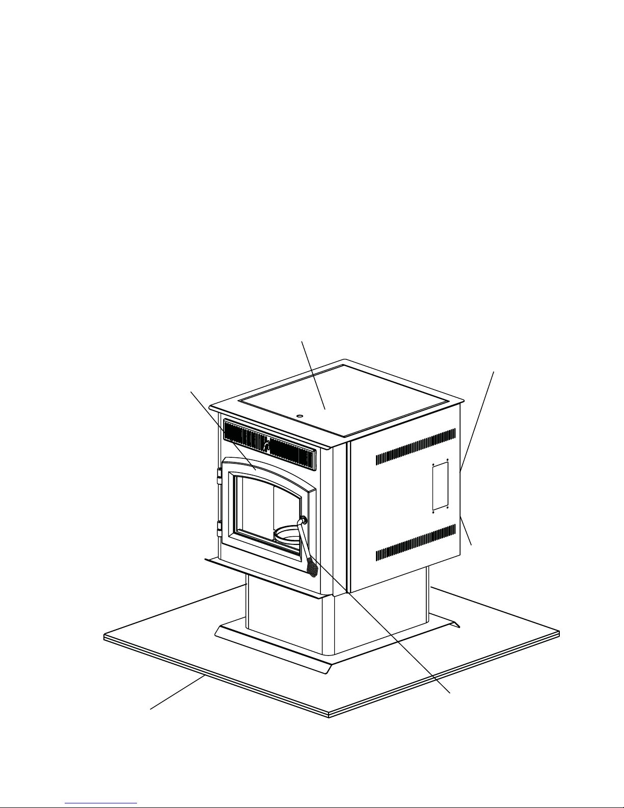
1.0 INSTALLATION OVERVIEW
1.1 STOVE
Rating plate, see
“RATING PLATE
INFORMATION”
section.
Door, see “FINISHING - INSTALLING
THE VIEWING DOOR” section.
Venting, see “GENERAL VENTING”
and “INSTALLATION” sections.
Floor, see “INSTALLATION PLANNING FLOOR PROTECTION REQUIREMENTS” section.
See “OUTSIDE AIR”
section.
Handle, see “DOOR
HANDLE INSTALLATION”
section.
W415-0865 / B / 05.26.11
Page 4
4
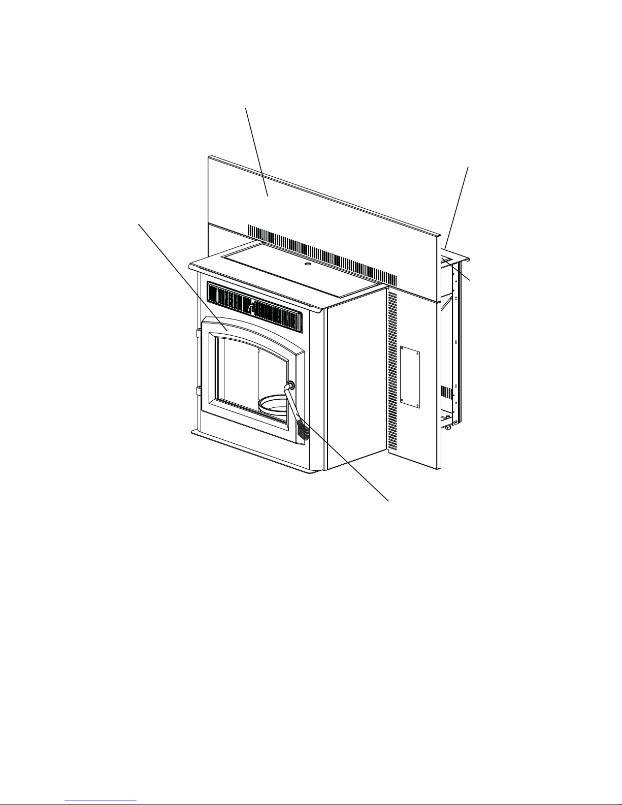
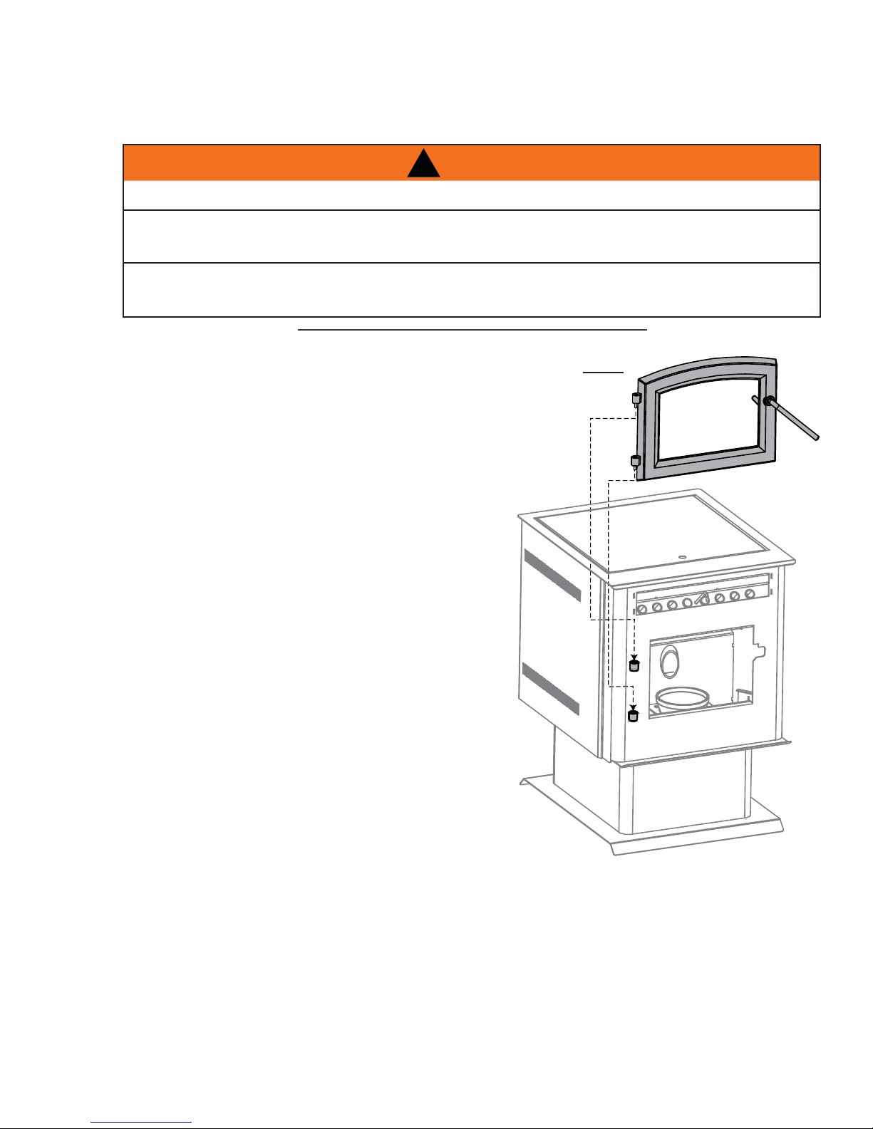
1.2 INSERT
Door, see “FINISHING INST ALLING THE VIEWING DOOR” section.
Flashing, see “FLASHING
INSTALLATION” section.
Venting, see “VENTING” and
“INSTALLATION” sections.
Rating plate, see
“RATING PLATE
INFORMATION”
section.
W415-0865 / B / 05.26.11
Handle, see “DOOR
HANDLE INSTALLATION”
section.
Page 5

2.0 INTRODUCTION
• THIS APPLIANCE IS HOT WHEN OPERATED AND CAN CAUSE SEVERE BURNS IF CONTACTED.
• Do not operate appliance before reading and understanding operating instructions. Failure to operate appliance according to
operating instructions could cause fi re or injury. Contact the local building or fi re authority and follow their guidelines. Notify
your insurance company of this appliance as well.
• Never try to repair or replace any part of the appliance unless instructions are given in this manual. All other work should be
done by a trained technician.
• Risk of burns. The appliance should be turned off and cooled before servicing.
• Do not operate without fully assembling all components.
• Do not install damaged, incomplete or substitute components.
• Risk of cuts and abrasions. Wear protective gloves and safety glasses during installation. Sheet metal edges may be sharp.
• Children and adults should be alerted to the hazards of high surface temperature and should stay away to avoid burns or
clothing ignition. Toddlers, young children and others may be susceptible to accidental contact burns. A physical barrier is recommended if there are at risk individuals in the house. To restrict access to an appliance or stove, install an adjustable safety
gate to keep toddlers, young children and other at risk individuals out of the room and away from hot surfaces.
• Clothing or other fl ammable material should not be placed on or near the appliance.
• Due to high temperatures, the appliance should be located out of traffi c and away from furniture and draperies.
• Ensure you have incorporated adequate safety measure to protect infants/toddlers from touching hot surfaces.
• Even after the appliance is out, the glass and/or screen will remain hot for an extended period of time.
• Check with your local hearth specialty dealer for safety screens and hearth guards to protect children from hot surfaces.
These screens and guards must be fastened to the fl oor.
• Any safety screen or guard removed for servicing must be replaced prior to operating the appliance.
• It is imperative that the control compartments, burners and circulating blower and its passageway in the appliance and venting
system are kept clean. The appliance and its venting system should be inspected before use and at least annually by a qualifi ed service person. More frequent cleaning may be required due to excessive lint from carpeting, bedding material, etc. The
appliance area must be kept clear and free from combustible materials, gasoline and other fl ammable vapors and liquids.
• Under no circumstances should this appliance be modifi ed.
• Do not use this appliance if any part has been under water. Immediately call a qualifi ed service technician to inspect the appli-
ance and to replace any part of the control system and any gas control which has been under water.
• Do not operate the appliance with the glass door removed, cracked or broken. Replacement of the glass should be done by a
licensed or qualifi ed service person. The viewing door and ashpan must be closed and latched during operation.
• Do not strike or slam shut the appliance glass door.
• Only doors / optional fronts certifi ed with the unit are to be installed on the appliance.
• Keep the packaging material out of reach of children and dispose of the material in a safe manner. As with all plastic bags,
these are not toys and should be kept away from children and infants.
• If the appliance is not properly installed, a house fi re may result. Do not expose the appliance to the elements (ex. rain, etc.)
and keep the appliance dry at all times. Wet insulation will produce an odour when the appliance is used.
• The chimney must be sound and free of cracks. Clean your chimney a minimum of twice a year and as required.
• The heater is designed and approved for pelletized wood fuel only. Any other type of fuel burned in this heater will void the
warranty and safety listing.
• Do not start a fi re with chemicals or fl uids such as gasoline, engine oil, etc.
• Ashes must be disposed in a metal container with a tight lid and placed on a non-combustible surface well away from the
home or structure.
• Your appliance requires periodic maintenance and cleaning. Failure to maintain your appliance may lead to smoke spillage in
your home.
• The exhaust system must be completely straight and properly installed. It is recommended that the pellet vent joints be sealed
with a minimum 500°F (260°C) silicone sealant. Install according to the vent manufacturer’s instructions.
• Ensure clearances to combustibles are maintained when building a mantel or shelves above the appliance. Elevated
temperatures on the wall or in the air above the appliance can cause melting, discolouration or damage to decorations, a T.V.
or other electronic components.
• During a power outage this appliance will not operate. If a power outage does occur, check the appliance for smoke spillage
and open a window if any smoke spills into the room.
• Keep foreign objects out of the hopper.
• Disconnect the power cord before performing any maintenance. NOTE: Turning the pellet feed to “OFF” does not discon-
nect all power to the heater.
• Do not throw this manual away. This manual has important operating and maintenance instructions that you will need at a
later time. Always follow the instructions in this manual.
• At no point should you use fi rewood or fi relogs in this appliance. The use of which could cause a house fi re.
• This appliance must be connected to a standard 115 V, 50Hz grounded electrical outlet. Do not use an adapter plug or sever
the grounding prong. Do not route the electrical cord underneath, in front of, or over the appliance.
• When installed in a mobile home, the appliance must be bolted to the fl oor, have outside air, and NOT BE INSTALLED IN THE
BEDROOM (per H.U.D. requirements). Check with local building offi cials.
• The exhaust system should be checked and cleaned once a year minimum for any build-up of soot or creosote.
• This heater becomes very hot, you MUST wear heat resistant gloves when cleaning or handling this heater.
!
WARNING
5
3.8B
W415-0865 / B / 05.26.11
Page 6
6
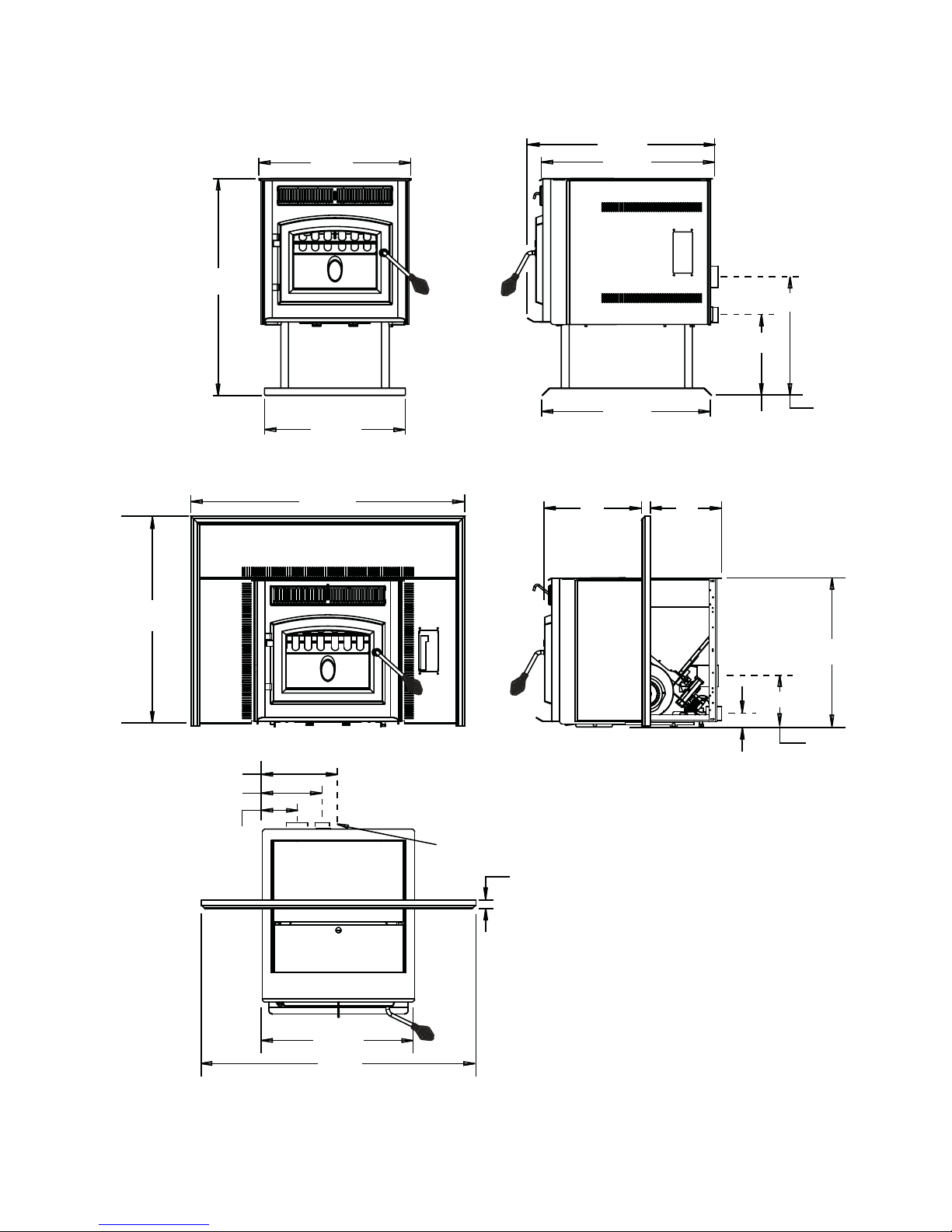
2.1 DIMENSIONS
2.1.1 STOVE
1
21
/4"
5
30
/16"
11
19
/16"
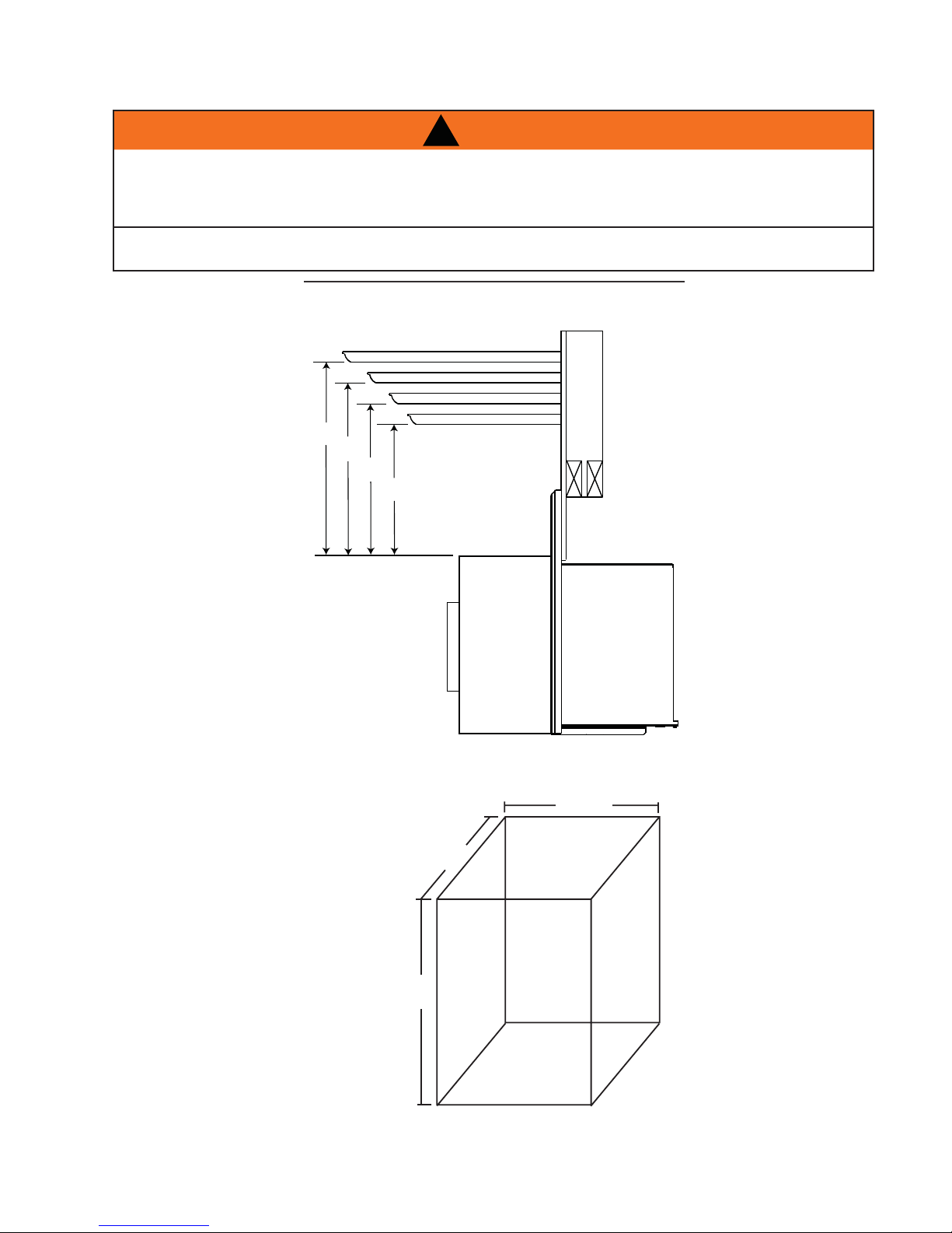
2.1.2 INSERT (COMPLETE WITH FLASHING)
3
38
/8"
7
25
/8"
1
24
/4"
17
"
5
11
/8"
1
23
/2"
CENTRE LINE
OF AIR INTAKE
B
A
*
*
CENTRE
LINE OF
EXHAUST
3
29
/8"
1
8
/2"
CENTRE LINE
OF AIR INTAKE
5
5/
"
CENTRE LINE
8
OF EXHAUST
10
13
20
/16"
1
7
/8"
7
1
5
/8"
/8"
CENTRE LINE
CENTRE
LINE OF
EXHAUST
OF AIR INTAKE
CENTER LINE
OF INSERT
1
1
/4"
1
21
/4"
3
38
/8"
* A and B are adjustable, see "SPECIFICATIONS" section.
W415-0865 / B / 05.26.11
Page 7
7
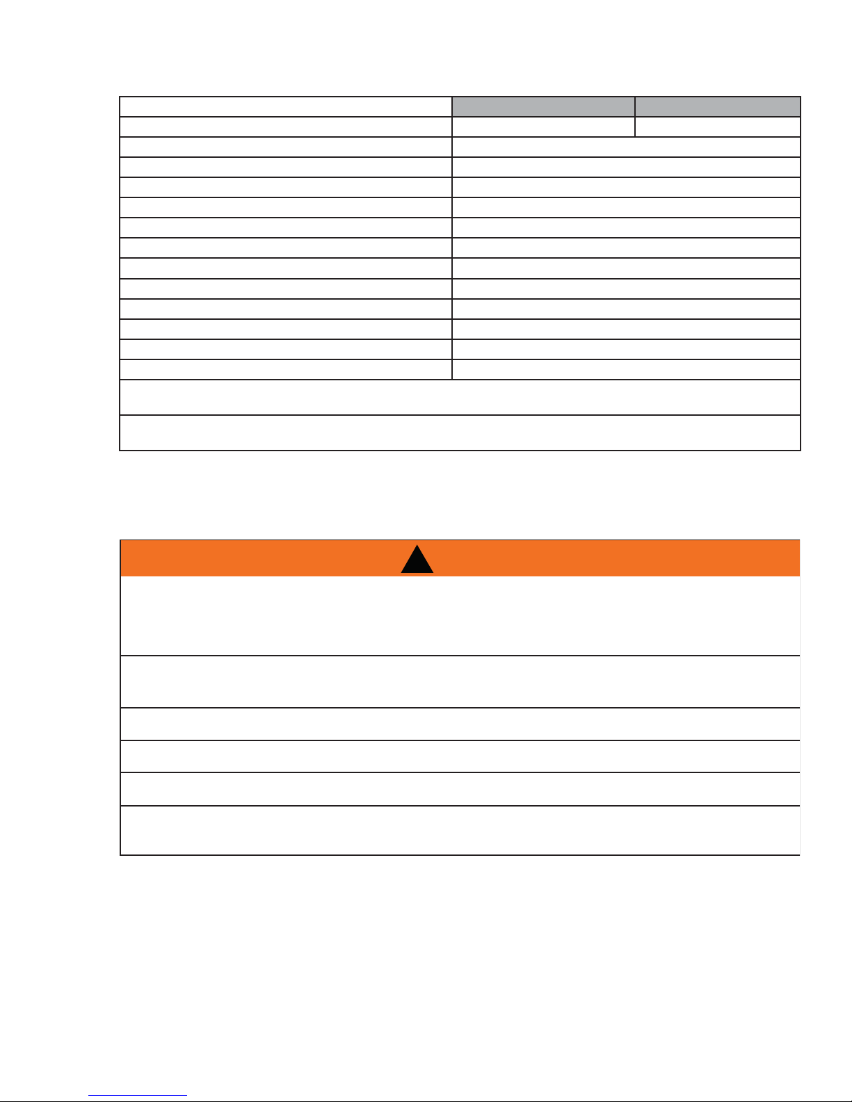
2.2 SPECIFICATIONS
Adjuistable Flashing 11" to 13" 10 1/2" to 12 1/2"
Electrical Rating 115 Volts, 3.6 Amps, 60Hz
Watts During Ignition Sequence 400 (approximately)
Watts During Operation 180 (approximately)
Weight Stove 158 lbs / Insert 140 lbs
Exhaust Collar 3"
Intake Collar 2"
Hopper Capacity 45 Pounds
EPA Exempt
Burn Rate 1.5 to 4.5 (Pounds Per Hour)
BTU/H 12750 to 38250
Approximate Maximum Heating Capacity (in square feet)* 800 to 2000 Sq. Feet
Maximum Burn Time on Low Burn** 30 Hours
* Heating capacity will vary depending on the home's fl oor plan, degree of insulation, and the outside temperature. It is
also affected by the fuel size, quality, and moisture level.
** Small pellets will increase or decrease the stated burn rates and burn times. Differences of plus or minus 20% depend-
ing on fuel quality may occur.
AB
2.3 GENERAL INSTRUCTIONS
ALL WIRING SHOULD BE DONE BY A QUALIFIED ELECTRICIAN AND SHALL BE IN COMPLIANCE
WITH LOCAL CODES. IN THE ABSENCE OF LOCAL CODES, USE THE CURRENT CSA C22.1
CANADIAN ELECTRIC CODE (IN CANADA) OR THE ANSI/NFPA NO. 70 NATIONAL ELECTRIC CODE
DO NOT CONNECT THIS APPLIANCE TO A CHIMNEY FLUE SERVING ANOTHER APPLIANCE. DO
NOT CONNECT TO ANY AIR DISTRIBUTION DUCT OR SYSTEM.
PROVIDE ADEQUATE CLEARANCE FOR SERVICING AND OPERATING THE APPLIANCE.
PROVIDE ADEQUA TE VENTILA TION.
NEVER OBSTRUCT THE FRONT OPENING OF THE APPLIANCE.
OBJECTS PLACED IN FRONT OF THE APPLIANCE MUST BE KEPT A MINIMUM OF 48” FROM THE
FRONT FACE OF THE APPLIANCE.
!
WARNING
IN THE UNITED STATES.
W415-0865 / B / 05.26.11
Page 8

8
Thank you for purchasing a Wolf Steel Ltd. Pellet Appliance. This appliance is designed for use with Pelletized
Wood Only.
Please read this entire manual before installation and use of this pellet fuel-burning room appliance. Failure to
follow these instructions could result in property damage, bodily injury or even death.
Keep this manual handy for future reference.
This Pellet Appliance, when installed, must be electrically grounded in accordance with the local codes, or in
the absence of local codes, use the current CSA C22.1 Canadian Electrical Code in Canada or the ANSI/NFPA
70 National Electrical Code in the United States.
This appliance will not operate using natural draft or without a power source for the blower systems and fuel
feed system.
The protective wrap on plated parts is best removed when the assembly is at room temperature but this can be
improved if the assembly is warmed, using a hair dryer or similar heat source.
If the appliance is installed directly on carpeting, vinyl tile or other combustible material other than wood
fl ooring, the appliance shall be installed on a metal or wood panel extending the full width and depth.
2.4 GENERAL INFORMATION
4.5
2.4.1 FUEL
This appliance is designed to burn wood pellet fuel. In addition, a corn/wood pellet mixture with a maximum
50% corn can be burned. Burning any other fuel, that is not approved for use with this appliance, will void the
warranty.
Important: The corn/wood pellet mixture needs to be mixed evenly before being put into the hopper.
W415-0865 / B / 05.26.11
Page 9

2.4.2 PELLET SPECIFICATIONS
IT IS IMPORTANT TO SELECT AND USE ONLY PELLETS THAT ARE DRY AND FREE OF DIRT OR ANY
IMPURITIES SUCH AS HIGH SALT CONTENT. DIRTY FUEL WILL ADVERSELY AFFECT THE OPERA-
TION AND PERFORMANCE OF THE APPLIANCE AND WILL VOID THE WARRANTY. THE PELLET
FUEL INSTITUTE (P.F.I.) HAS ESTABLISHED STANDARDS FOR WOOD PELLET MANUFACTURERS.
WE RECOMMEND THE USE OF PELLETS THAT MEET OR EXCEED THESE STANDARDS. ASK YOUR
DEALER FOR A RECOMMENDED PELLET TYPE.
Pellet quality is important, please read the following:
Your Wolf Steel Ltd. Pellet Appliance has been designed to burn premium hard or soft wood pellets only. Do
not use any other type of fuel such as fi re logs or fi re starting pellets, as this will void the warranties stated in
this manual.
The performance and heat output of the pellet appliance is directly related to the quality and moisture of the
pellets. Store pellets in a cool dry area to prevent moisture absorption.
P.F.I. PELLET STANDARDS:
Fines (fi ne particles) 1% maximum through a 1/8" screen
Bulk Density 40 pound per cubic foot minimum
Size 1/4" to 5/16" diameter, 1/2" - 1 1/2" long maximum
Ash Content 1% maximum (Premium grade)
3% maximum (Standard grade)
Moisture Content 8% maximum
Heat Content Approximately 8200 BTU per pound minimum
!
WARNING
9
64.1
If the fuel does not comply to
this standard the appliance may
not operate as designed.
We recommend the use of premium grade (1% ash content)
for longer appliance life and less
frequent cleaning.
2.4.3 CORN SPECIFICATIONS
Use only clean-shelled corn with a moisture content less than 15% and approximate fuel value of 7,000 BTU/
lb (16,200 kJ/kg). Do not attempt to burn corn with higher moisture content or burn lesser grade fuels. Do not
burn other types of agricultural pellets or by-products (alfalfa, cherry pits, olive pits, nut shells, etc.) as they are
not permitted to be burned in this appliance.
Corn must be clean and free of debris. Never burn corn right from the fi eld. Damage caused by dirty corn is
not covered by the Lifetime Limited Warranty. Ask for screened corn only. Stalk parts, excessive fi nes and
cob remnants will clog the air fl ow holes in the burn plate. Check the corn for foreign objects.
Use only a maximum 50% corn to pellet mixture.
W415-0865 / B / 05.26.11
Page 10
10
TPS
Corner Ins
Corner In
6”
3”
6”6”
ON, L4M 0G8 CANADAON, L4M 0G8 CANADA
LES VÊTEMENTS ET LES MEUBLES À LES VÊTEMENTS ET LES MEUBLES
OU AUX CODES DU BÂTIMENT ODES DU BÂTIMENT
TRAVERSE UN MUR OU UN N MUR OU
6”6”
FloorFl
ProtectionProt
Protection de
pl
plancher
Installations
à
à travers le
murmur
2.4.4 SAFETY FEATURES
HIGH LIMIT SWITCH: Your appliance is equipped with a high limit switch. In the event that the temperature of
the appliance approaches an unsafe operating temperature, this switch will shut down the pellet feed, which
will eventually shut down the unit. If this happens, it is important to fi nd out why the unit overheated. Contact
your local dealer.
LOW LIMIT SWITCH: This switch will automatically shut down the appliance if the fi re goes out or fails to light
within 15 minutes.
HOPPER DOOR INTERLOCK: Your appliance is equipped with a micro switch in the hopper assembly that
shuts-off the auger when the hopper door is opened. Closing the door switches the auger back on, allowing
pellets to feed again.
VACUUM SWITCH: This switch will sense lack of air fl ow through the appliance and shut down the pellet feed.
This lack of fl ow could be caused by a blocked vent.
POWER FAILURE: In the event of a power failure, the appliance will shut down. Once power is restored, the
appliance will re-start, unless the convection air temperature has gone above the high limit switch setting. If
this happens, contact your local dealer.
2.4.5 EPA COMPLIANCE
This appliance is EPA exempt from Phase II
prerequisites, but complies with Oregon /
Washington emissions requirements.
2.5 RATING PLATE INFORMATION
- INSTALL AND USE ONLY IN ACCORDANCE WITH THE
MANUFACTURER’S INSTRUCTIONS AND LOCAL
BUILDING CODES.
- MINIMUM CEILING HEIGHT: 7FT (2.13M) HEARTH
9700539 (WSL)
4001657 (NGZ)
4001658 (NAC)
4001659 (WUSA)
REFERENCE
#16544
CAUTION: HOT WHILE IN OPERATION. DO NOT TOUCH. KEEP CHILDREN,
CLOTHING AND FURNITURE AWAY. CONTACT MAY CAUSE SKIN BURNS.
- INSTALLER ET UTILISER CONFORMÉMENT AUX INSTRUCTIONS DU FABRICANT ET
AUX CODES DU BÂTIMENT LOCAUX.
- HAUTEUR DE PLAFOND MINIMALE 7 PI. (2,13 m)
BASE DE PROTECTION/PROTECTION DE PLANCHER COMBUSTIBLE : SI INSTALLÉ
SUR UN PLANCHER COMBUSTIBLE, L’APPAREIL DOIT ÊTRE PLACÉ SUR UNE
PLAQUE PROTECTRICE INCOMBUSTIBLE S’ÉTENDANT SUR 6” À L’AVANT.
- NE PAS RACCORDER CET APPAREIL À LA CHEMINÉE D’UN AUTRE APPAREIL.
- REMPLACER LA VITRE PAR UNE VITRE EN CÉRAMIQUE SEULEMENT.
DANGER : RISQUE DE SECOUSSE ÉLECTRIQUE. DÉBRANCHER L’ALIMENTATION
ÉLECTRIQUE AVANT DE PROCÉDER À L’ENTRETIEN.
- GARDER LA PORTE VITRÉE ET LA PORTE DU TIROIR À CENDRES BIEN FERMÉES
DURANT LE FONCTIONNEMENT.
- CONTACTER LES AUTORITÉS LOCALES DU BÂTIMENT ET DU SERVICE DES
INCENDIES AU SUJET DES RESTRICTIONS ET DES INSPECTIONS D’INSTALLATION
DANS VOTRE RÉGION.
- PEUT ÊTRE INSTALLÉ DANS UNE MAISON MOBILE SI INSTALLÉ CONJOINTEMENT
AVEC UNE PRISE D’AIR EXTÉRIEUR.
- SE RÉFÉRER AUX INSTRUCTIONS D’INSTALLATION OU AUX CODES DU BÂTIMENT
LOCAUX LORSQUE LE SYSTÈME D’ÉVACUATION TRAVERSE UN MUR OU UN
PLAFOND COMBUSTIBLES.
- COMBUSTIBLE : POUR USAGE AVEC DES GRANULES SEULEMENT.
ATTENTION : L'APPAREIL EST CHAUD LORSQU’IL FONCTIONNE. NE PAS
TOUCHER. TENIR LES ENFANTS, LES VÊTEMENTS ET LES MEUBLES À
L’ÉCART. LE CONTACT PEUT CAUSER DES BRÛLURES DE PEAU.
WOLF STEEL LTD.
24 NAPOLEON ROAD, BARRIE, ON, L4M 0G8 CANADA
EXTENSION / COMBUSTIBLE FLOOR PROTECTION: IF
INSTALLED ON A COMBUSTIBLE FLOOR, UNIT MUST BE
PLACED ON A NON-COMBUSTIBLE FLOOR PROTECTOR
EXTENDING 6” IN FRONT.
- DO NOT CONNECT THIS UNIT TO A CHIMNEY FLUE
SERVING ANOTHER APPLIANCE.
- REPLACE GLASS WITH ONLY CERAMIC GLASS.
DANGER: RISK OF ELECTRICAL SHOCK. DISCONNECT
POWER BEFORE SERVICING UNIT.
- KEEP VIEWING AND ASH REMOVAL DOORS TIGHTLY
CLOSED DURING OPERATION.
- CONTACT LOCAL BUILDING AND FIRE OFFICIALS ABOUT
RESTRICTIONS AND INSTALLATION INSPECTION IN YOUR
LOCAL AREA.
- SUITABLE FOR USE IN MOBILE HOMES WHEN USED WITH
OUTSIDE AIR INSTALLATION KIT.
- REFER TO INSTALLATION INSTRUCTIONS OR LOCAL
BUILDING CODES WHEN PASSING EXHAUST SYSTEM
THROUGH COMBUSTIBLE WALL OR CEILING.
- FUEL: FOR USE WITH PELLET FUEL ONLY.
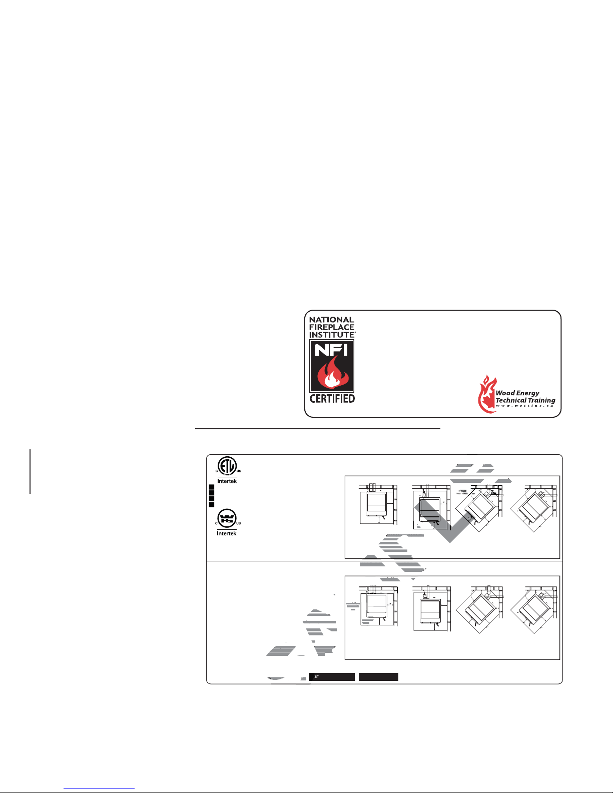
We suggest that our pellet hearth
products be installed and serviced by
professionals who are certified in the U.S.
by the National Fireplace Institute
as NFI Pellet Specialists or who are
certified in Canada by
Wood Energy Technical
www.nficertified.org
TPS35
Training (WETT).
3”
Through
Wall
Installation
Floor
Protection
MINIMUM CLEARANCES TO COMBUSTIBLE
SIDE 6”
REAR 3”
CORNER 2”
CEILING 48”
U.S. ENVIROMENTAL PROTECTION AGENCY Certified to comply with July 1992 Particulate Emission Standards
MODÈLE TPS35 APPAREIL DE CHAUFFAGE AUX GRANULES HOMOLOGUÉ TESTÉ SELON LES
Installations
Installations
à travers le
travers le
mur
Protection de
Protection de
plancher
ancher
DÉGAGEMENTS MINIMAUX AUX MATÉRIAUX COMBUSTIBLES
CÔTÉ 6”
ARRIÈRE 3”
COIN 2”
PLAFOND 48”
Certifié conforme à la norme d'émanation de particules de juillet 1992 du U.S. ENVIROMENTAL PROTECTION AGENCY
DATE CODE / DE DATE
66.1A
MODEL TPS35 LISTED PELLET FUEL BURNING ROOM HEATER TESTED TO:
ASTM E 1509, ULC/ORD C1482-M90, ULC S627
Straight Installation Corner Installation
6”
6”
Installation droite
6”
3”
2”
Tee
Interior
Vertical
Vent
Floor
6”
Protection
2”
6”
6”
Floor Protection
INPUT RATING
MIN 1.5 LB/HR
MAX 4.5 LB/HR
ELECTRICAL RATING
120V 3.6A 60HZ
NORMES : ASTM E 1509, ULC/ORD1482-M90, ULC S627
Installation de coin
Évents à
travers le
mur
6”
6”
Coude
2”
45°
45°
2”
6”
6”
Protection de
plancher
IDÉBIT D’ALIMENTATION
MIN. 1.5 LB/H
MAX. 4.5 LB/H
CARACTÉRISTIQUES ÉLECTRIQUES
120 V 60 Hz
Évents
verticaux
intérieurst
Protection de
plancher
3”
2”
Té
Interior
Vertical
Vent
Évents
verticaux
intérieurs
®
(NFI)
2”
6”
2”
6”
Tee
2”
6”
Floor Protection
Té
2”
6”
Protection de
plancher
W385-0509 / B
Stove rating plate illustrated
For rating plate location, see “INSTALLATION OVERVIEW” section.
This illustration is for reference only. Refer to the rating plate on the appliance for accurate information.
W415-0865 / B / 05.26.11
Page 11

3.0 INSTALLATION PLANNING
!
WARNING
READ ENTIRE MANUAL BEFORE YOU INSTALL OR USE THIS APPLIANCE. FAILURE TO FOLLOW THE
INSTRUCTIONS MAY RESULT IN PROPERTY DAMAGE, BODILY INJURY OR EVEN DEATH.
USE ONLY WOLF STEEL APPROVED OPTIONAL ACCESSORIES AND REPLACEMENT PARTS WITH
THIS APPLIANCE. USING NON-LISTED ACCESSORIES AND REPLACEMENT PARTS (BLOWERS,
DOORS, LOUVRES, TRIMS, GAS COMPONENTS, VENT COMPONENTS, ETC.) COULD RESULT IN A
SAFETY HAZARD AND WILL VOID THE LIMITED LIFETIME WARRANTY.
Check with local building offi cials for any permits required for installation of this pellet appliance and notify your
insurance company before proceeding with installation.
Before installing we recommend placing the appliance outside and load 5 pounds of pellets inside the hopper.
Plug the appliance in and let it run on HIGH until the pellets run out. This will cure the paint and burn off most
of the oils on the steel, thereby minimizing any smell inside the home.
3.1 INSTALLATION OPTIONS
Stove model:
To install in a Residential or Mobile Home see "MOBILE HOME INSTALLATION" section. For alcove installations see "ALCOVE INSTALLATION REQUIREMENTS" section. For horizontal vent or vertical vent see
"VENTING" section. Outside air, see "OUTSIDE AIR" section.
11
68.1
Insert model:
To install as an insert into an existing masonry appliance or factory built appliance see "VENTING" section. To
install into a combustible enclosure, see "INSTALLATION INTO A COMBUSTIBLE ENCLOSURE" section.
3.2 APPLIANCE PLACEMENT
Have an authorized dealer install the appliance. If you install the appliance yourself, have your dealer review
your installation plans and/or installation.
Draw out a detailed plan of the installation including dimensions and verify the dimensions with the requirements listed in this manual.
You may wish to adjust the appliance position slightly to ensure the vent does not intersect with a framing
member. Appliance must be positioned so that no combustibles are within, or can swing within (e.g. drapes,
doors), 48” of the front of the appliance.
67.1A
W415-0865 / B / 05.26.11
Page 12
12
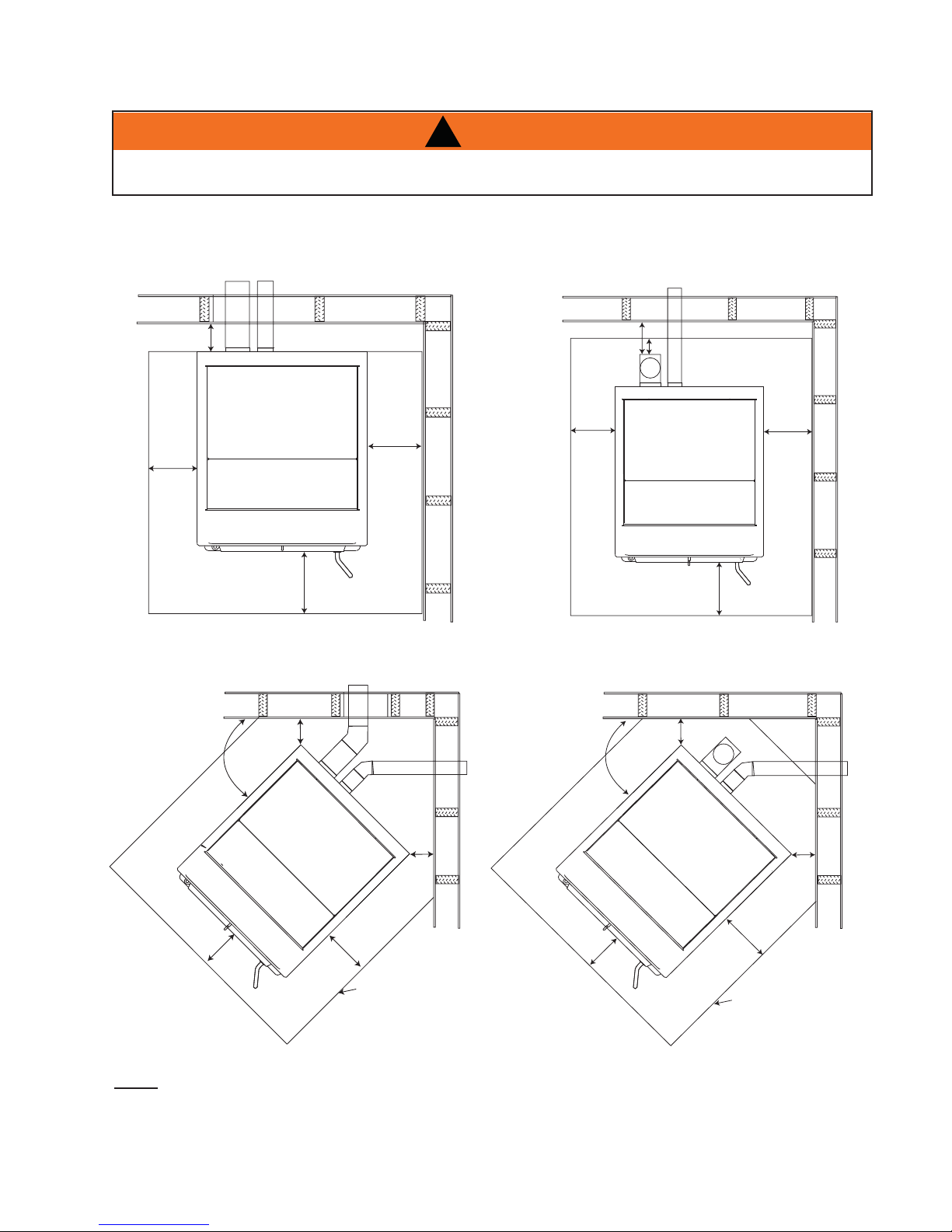
3.3 MINIMUM CLEARANCE TO COMBUSTIBLES
!
WARNING
DO NOT INSTALL INTO ANY AREA HAVING LESS THAN 48" (CEILING TO APPLIANCE BOTTOM,
EXCLUDING HEARTH HEIGHT).
3.3.1 STRAIGHT INSTALLATION
Through the Wall Installations complete
with outside air
Interior Vertical Vents
3”
6”
Floor
6”
Protection
3.3.2 CORNER INSTALLATION
Through the Wall Vents complete with outside air Interior Vertical Vents
2”
45°
6”
45°
Elbow
6”
Floor
Protection
45°
3”
2”
6”
6”
2”
6”
NOTE: If interior vertical pellet vent is used, the clearance to the back wall is determined by the upward-turning elbow or "Tee". It will vary in depth depending on the brand of pellet vent used (it is approximately 5"). Before placing the appliance, connect the elbow or "Tee" and allow for the minimum
3" clearance to the combustible wall.
W415-0865 / B / 05.26.11
2”
6”
Floor Protection
6”
2”
6”
Floor Protection
Page 13
3.4 FLOOR PROTECTION REQUIREMENTS INSTALLATION
The appliance must be installed on a non-combustible fl oor protector extending the full depth of the appliance
and extending a minimum 6" in front and on either side (minimum .018" thick - 26 gauge) of the fuel loading
and ash removal openings.
The fl oor protector must extend under and 2" beyond each side and rear of a "Tee" (if used).
NOTE: Floor protection is required for spark and ash shielding, but not for limiting fl oor temperatures
from the radiant heat of the appliance. The appliance was designed and safety tested so that without
any protection, the fl oor would not overheat.
Refer to local building codes for suitable fl oor protection materials.
3.5 OUTSIDE AIR
Available from your Authorized Dealer (114KT)
Outside air must not be drawn from an enclosed space (garage, unventilated crawl space).
NOTE: Wolf Steel Ltd. strongly suggests using outside air for all residential installations, especially for
those that are energy effi cient, air-tight homes.
Outside air supply must not be over 15' long.
13
Outside air vents must be made with 1 3/4" diameter or larger metal or aluminum duct with a metal screen attached to the end to keep out rodents (P.V.C. or other materials may not be used).
The outside air inlet must not be above or within 12" of the chimney termination, must have a rain cap or downturned elbow to prevent the water from entering and be located so that it will not become plugged by snow or
other material.
Outside air is required for all combustible built-in enclosure installations.
3.6 MOBILE HOME
THE STRUCTURAL INTEGRITY OF THE MANUFACTURED HOME FLOOR, WALL, AND CEILING ROOF
Installation into a manufactured home or mobile home should be installed in
accordance with the Manufactured Home Construction and Safety Standard,
Title 24 CFR, Part 3280, in the United States or the Mobile Home Standard,
CAN/CSA Z240 MH Series, in Canada.
The appliance must be grounded to the steel chassis of the mobile home
(Some states do not require this; check with your local building department).
!
WARNING
DO NOT INSTALL IN A SLEEPING ROOM.
MUST BE MAINTAINED.
STOVE
ILLUSTRATED
29.4A
W415-0865 / B / 05.26.11
Page 14
14
4.0 VENTING
4.1 TYPE OF VENT
Must be an approved 3" or 4" diameter Type "L" or "PL" vent, vented to the outside or connect the vent to a
factory built type "A" chimney using an adaptor; and/or stainless steel chimney liner for masonry appliance installations. Use 4" diameter vent if vent or liner height is over 15' or if installation is over 4,000' above sea level.
4.2 INSTALLING THE PELLET VENT
PELLET VENT MUST MAINTAIN A MINIMUM 3" CLEARANCE TO ANY COMBUSTIBLE (INSTALL VENT
AT CLEARANCES SPECIFIED BY THE VENT MANUFACTURER).
DO NOT CONNECT THE PELLET VENT TO A VENT OR CHIMNEY SERVING ANY OTHER APPLIANCE
DO NOT INSTALL A FLUE DAMPER IN THE EXHAUST VENTING SYSTEM OF THIS UNIT.
!
WARNING
OR HEATER.
The vent must have a support bracket every 5’ when on
the exterior wall. To achieve optimum performance, keep
vent runs as short as possible, especially on horizontal
installations.
MAXIMUM VENTING: Maximum venting height is 33’.
Maximum horizontal vent run is 10’. Use no more than
180° of elbows (two 90’ elbows, or two 45’ elbows and
one 90’ elbow, etc), excluding the tee and the termination.
VENT INST ALLATION: Termination must exhaust above
the air inlet elevation, and parallel or above the exhaust
output of the pellet appliance. It is recommended that at
least 3’ of vertical pipe be installed to create some natural
draft. This is to help prevent the possibility of smoke or
odour entering the home during the appliance shut down
or in the event of a power outage. Horizontal sections
must have a 1/4” rise every 12” of travel if longer than 3’.
The pellet vent connections must be sealed with HI-Temp
RTV Silicone and screwed together with at least 3 3/8”
long stainless steel screws. Seal each vent section by
injecting a liberal amount of 500°F (260°C) RTV silicone
sealant into the gap. We recommend sealing the outside
of the vent connections to permit easier access when
servicing.
Use 4” diameter
“L” vent if
venting in this
region.
Use 3” or 4”
diameter “L”
vent if venting
in this region.
33’
30’
25’
20’
15’
10’
5’
0’
4.3 VENTING THE PELLET APPLIANCE
Use an approved wall thimble when passing the vent through walls and a ceiling support / fi restop spacer when
passing the vent through ceilings (maintain a 3" clearance to any combustibles).
W415-0865 / B / 05.26.11
0’
7.5A
5’
10’
Page 15
4.4 PELLET VENT TERMINATION
The vent termination must have an approved cap (to prevent water from entering) or a 45° downturn.
If the termination is located on a windy side of the house, a shield is recommended to prevent soot from building up on the side of the house.
Horizontal terminations must protrude 12" from the wall, vertical terminations require a minimum 24" above the
highest point that it penetrates through the roof.
Depending on pellet quality, vent confi guration and air settings, black soot may occur on the terminal wall.
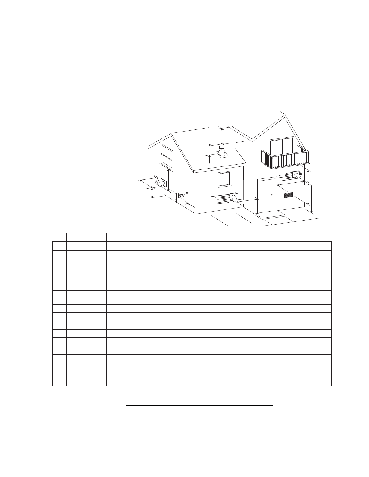
4.5 VENT TERMINAL CLEARANCES
15
E
C
K
J
G
I
F
H
D
B
B
A
L
E
NOTE: Illustration dimensions are to the center of
the exhaust exit point of the vent.
CLEARANCES
A 24” Clearance above grade, veranda porch, deck or balcony. (Including vegetation and mulch)
B
C 18”
D 0” Clearance to an outside corner wall.
E 3”
F 9” Clearance to a non-mechanical air supply inlet to the building or a combustion air inlet to any other appliance.
G 3” Clearance to a mechanical air supply inlet.
H 7’ ** Clearance above a paved sidewalk or paved driveway located on public property.
I 12” ** Clearance under a veranda, porch, deck or balcony.
J 24” Clearance above the roof.
K 2’ Clearance from an adjacent wall including neighbouring buildings.
L
* Recommended to prevent condensation on windows and thermal breakage
** This is a recommended distance. For additional requirements check local codes.
48” Clearance beside or below any windows or doors that open.
12” * Clearance above any window or door that opens.
Vertical clearance to ventilated soffi t located above the terminal within a horizontal distance of 2 feet
from the center line of the terminal.
Clearance to an inside combustible corner wall or protruding combustible obstructions (vent chase,
etc.)
3’ within a
height of 15 feet
above the meter
/ regulator as-
sembly
Clearance to each side of center line extended above natural gas or propane meter / regulator assembly
or mechanical vent.
12.7A
W415-0865 / B / 05.26.11
Page 16

16
4.6 STOVE VENTING INSTALLATION EXAMPLES
4.6.1 HORIZONTAL TERMINATION (THROUGH WALL)
3” Minimum
6”
Minimum
Floor
Protection
11 5/8”
17”
12” Minimum
Wall
Thimble
5’ Maximum
Outside Air
(Recommended)
4.6.2 VERTICAL RISE HORIZONTAL TERMINATION (THROUGH WALL)
Wall Thimble
Outside Air
(Recommended)
6”
Minimum
Floor
Protection
3”
2”
11 5/8”
17”
W415-0865 / B / 05.26.11
Page 17

4.6.3 VERTICAL TERMINATION
Storm Collar
17
Vertical Cap
Roof Flashing
Ceiling Support
Floor Protection
4.6.4 CLASS A CHIMNEY RETROFIT
Vertical Cap
Storm Collar
Vent must maintain 3”
clearance to combus-
tibles.
3”
2”
Outside air (Recommended)
(Installation showing inlet of out-
side air in ventilated crawl space)
Roof Flashing
Floor Protection
Class A Chimney
Ceiling Support
Vent must maintain
3” clearance to
combustibles.
3”
2”
Outside air
(Recommended)
(Installation showing inlet of outside
air in ventilated
crawl space)
W415-0865 / B / 05.26.11
Page 18

18
ect
N
Co
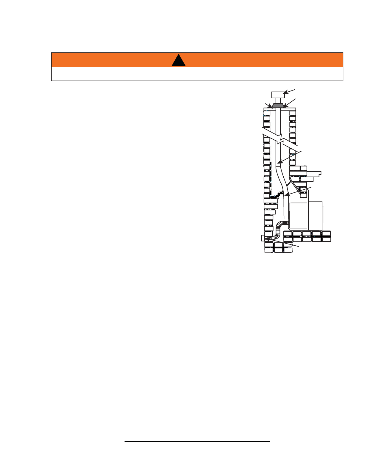
4.6.5 HEARTH MOUNT INSTALLATION
Chimney Cap
Pellet
Liner
Clean-out
ut
tee
Vertical Cap
Storm Collar
Pellet
Vent
torm
Flue Cover
6”
I
MIN
Floor Protection
Floor Prot
Bring outside air to the stove
Outside Air (Recommended)
W415-0865 / B / 05.26.11
Page 19
4.7 INSERT VENTING INSTALLATION EXAMPLES
e
r
o
Cap
Ver
4.7.1 TYPICAL EXISTING MASONRY INSTALLATION
!
WARNING
DO NOT REMOVE BRICKS OR MORTAR FROM THE FIREPLACE.
19
Prior to installation:
When installing the insert into a masonry fi replace, do not
remove any bricks or masonry. Do not weaken the structure,
or reduce the protection for combustible materials to less then
that required by the National Building Code. Bolted or screwed
together pieces (smoke shelf / defl ectors) may be removed,
but must be able to be re-installed if the appliance is removed.
External trim pieces, which do not affect the operation of the
fi replace, may be removed provided they are available to be reinstalled in event the appliance is removed.
A warning label must be attached to the back wall of the fi replace
stating that “This fi replace has been altered to accommodate a
fi replace insert and must be re-inspected by a qualifi ed person
prior to re-use as a fi replace”.
Non-combustible fl oor protection must cover the fl ooring
underneath, as well as extend a minimum of six inches in front
and to both sides of the appliance.
Clean all ashes out of the inside of the fi replace. Make sure
that the chimney and fi replace are free of cracks, loose mortar,
creosote deposits, blockage or other signs of deterioration.
If necessary, have any repair work done by a qualifi ed
professional before installing the appliance.
Cover Plate
Vertical Cap
Storm Collar
(Recommended)
rm Colla
t
Pellet
Liner
Flue
Cover
Outside Air
A. Remove the fi replace damper or fasten it permanently open.
B. Measure the throat of the fi replace and mark this shape on a piece of 24 gauge sheet metal (fl ue
cover). Cut a hole sized for the pellet liner to lie directly below the fi replace fl ue opening. Allow two
inches of material for a fl ange on all sides and cut to these measurements. Bend down the fl anges. If
you have never done this before, it might be a good idea to make a cardboard pattern and test it fi rst.
Fasten this fl ue cover in position as high as possible with two masonry screws per side through the
fl anges into the fi replace.
C. If you plan on connecting outside air it is recommended to do so at this time.
D. Install fl oor protection if necessary.
E. Connect the pellet vent with a clean out tee to the back of the insert. Refer to manufacturer’s
installation instructions to see “REAR TO TOP VENT CONVERSION INSTRUCTIONS” section and th
“GENERAL VENTING” section.
F. Run a liner down the chimney and connect to tee.
G. Position the insert in it’s fi nal location.
H. Pull the excess length of liner out through the top of the chimney. Trim the excess liner, install the cap
and cap the chimney.
62.3A
W415-0865 / B / 05.26.11
Page 20

20
e
4.7.2 FACTORY BUILT FIREPLACE
Prior to installation:
Do not weaken the structure, or reduce the protection for
combustible materials to less then that required by the National
Building Code. Bolted or screwed together pieces (smoke shelf /
defl ectors) may be removed, but must be able to be re-installed
if the appliance is removed.
External trim pieces, which do not affect the operation of the
fi replace, may be removed provided they are available to be reinstalled in event the appliance is removed.
A warning label must be attached to the back wall of the
fi replace stating that “This heater has been altered to
accommodate a fi replace insert and must be re-inspected by a
qualifi ed person prior to re-use as a factory built fi replace”.
Non-combustible fl oor protection must cover the fl ooring
underneath, as well as extend a minimum of six inches in front
and to both sides of the appliance.
Clean all ashes out of the inside of the fi replace. Make sure
that the chimney and fi replace are free of cracks, loose mortar,
creosote deposits, blockage or other signs of deterioration.
Storm
Collar
The smoke
shelf, damper
and baffles may
be removed
Vertical
Cap
Roof
Flashing
If necessary, have any repair work done by a qualifi ed
professional before installing the appliance.
A. Remove the fi replace damper or fasten it permanently
open.
B. Measure the throat of the fi replace and mark this shape on a piece of 24 gauge sheet metal (fl ue
cover). Cut a hole sized for the pellet liner to lie directly below the fi replace fl ue opening. Allow two
inches of material for a fl ange on all sides and cut to these measurements. Bend down the fl anges. If
you have never done this before, it might be a good idea to make a cardboard pattern and test it fi rst.
Fasten this fl ue cover in position as high as possible with two masonry screws per side through the
fl anges into the appliance.
C. If you plan on connecting outside air it is recommended to do so at this time.
D. Install fl oor protection if necessary.
E. Connect the pellet vent with a clean out tee to the back of the insert. Refer to manufacturer’s
installation instructions to see “REAR TO TOP VENT CONVERSION INSTRUCTIONS” section and th
“GENERAL VENTING” section.
F. Run a liner down the chimney and connect to tee.
G. Position the insert in it’s fi nal location.
Do not remove any part that would
alter the integrity in any way.
Floor Protection
H. Pull the excess length of liner out through the top of the chimney. Trim the excess liner, install the cap
and cap the chimney.
W415-0865 / B / 05.26.11
80.1
Page 21

5.0 FRAMING (INSERT ONLY)
!
WARNING
RISK OF FIRE!
IN ORDER TO AVOID THE POSSIBILITY OF EXPOSED INSULATION OR VAPOUR BARRIER COMING
IN CONTACT WITH THE APPLIANCE BODY, IT IS RECOMMENDED THAT THE WALLS OF THE
APPLIANCE ENCLOSURE BE “FINISHED” (IE: DRYWALL / SHEETROCK), AS YOU WOULD FINISH
ANY OTHER OUTSIDE WALL OF A HOME. THIS WILL ENSURE THAT CLEARANCE TO
COMBUSTIBLES IS MAINTAINED WITHIN THE CAVITY.
DO NOT NOTCH THE FRAMING AROUND THE APPLIANCE STAND-OFFS. FAILURE TO MAINTAIN
AIR SPACE CLEARANCE MAY CAUSE OVER HEATING AND FIRE. PREVENT CONTACT WITH
SAGGING OR LOOSE INSULATION OR FRAMING AND OTHER COMBUSTIBLE MATERIALS. BLOCK
OPENING INTO THE CHASE TO PREVENT ENTRY OF BLOWN-IN INSULATION. MAKE SURE
INSULATION AND OTHER MATERIALS ARE SECURED.
WHEN CONSTRUCTING THE ENCLOSURE ALLOW FOR FINISHING MATERIAL THICKNESS TO
MAINTAIN CLEARANCES. FRAMING OR FINISHING MATERIAL CLOSER THAN THE MINIMUMS
LISTED MUST BE CONSTRUCTED ENTIRELY OF NON-COMBUSTIBLE MATERIALS. MATERIALS
CONSISTING ENTIRELY OF STEEL, IRON, BRICK, TILE, CONCRETE, SLATE, GLASS OR PLASTERS,
OR ANY COMBINATION THEREOF ARE SUITABLE. MATERIALS THAT ARE REPORTED AS PASSING
ASTM E 136, STANDARD TEST METHOD FOR BEHAVIOUR OF MATERIALS IN A VERTICAL TUBE
FURNACE AT 750°C AND UL763 SHALL BE CONSIDERED NON-COMBUSTIBLE MATERIALS.
21
MINIMUM CLEARANCE TO COMBUSTIBLES MUST BE MAINTAINED OR A SERIOUS FIRE HAZARD
COULD RESULT.
THE APPLIANCE REQUIRES A MINIMUM ENCLOSURE HEIGHT. MEASURE FROM THE APPLIANCE
BASE.
IF STEEL STUD FRAMING KITS WITH CEMENT BOARD ARE PROVIDED, THEY MUST BE
INSTALLED.
71.1
W415-0865 / B / 05.26.11
Page 22
22
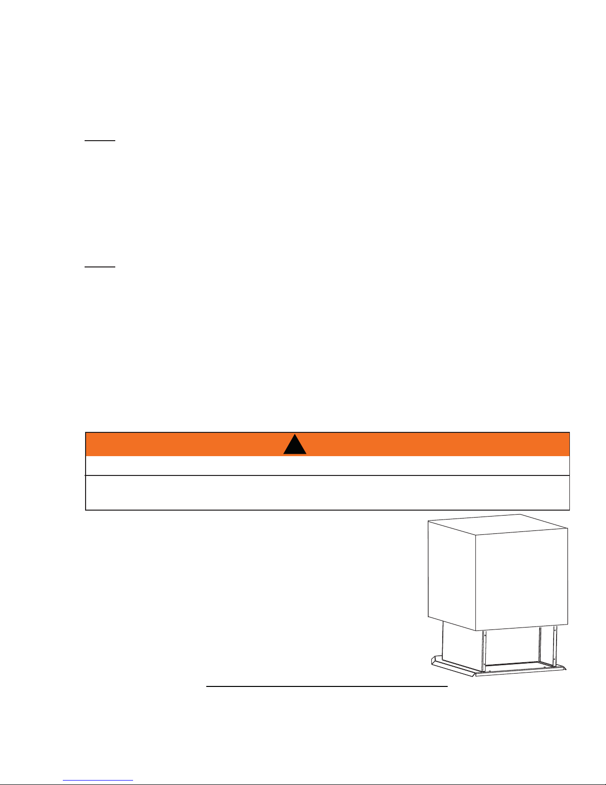
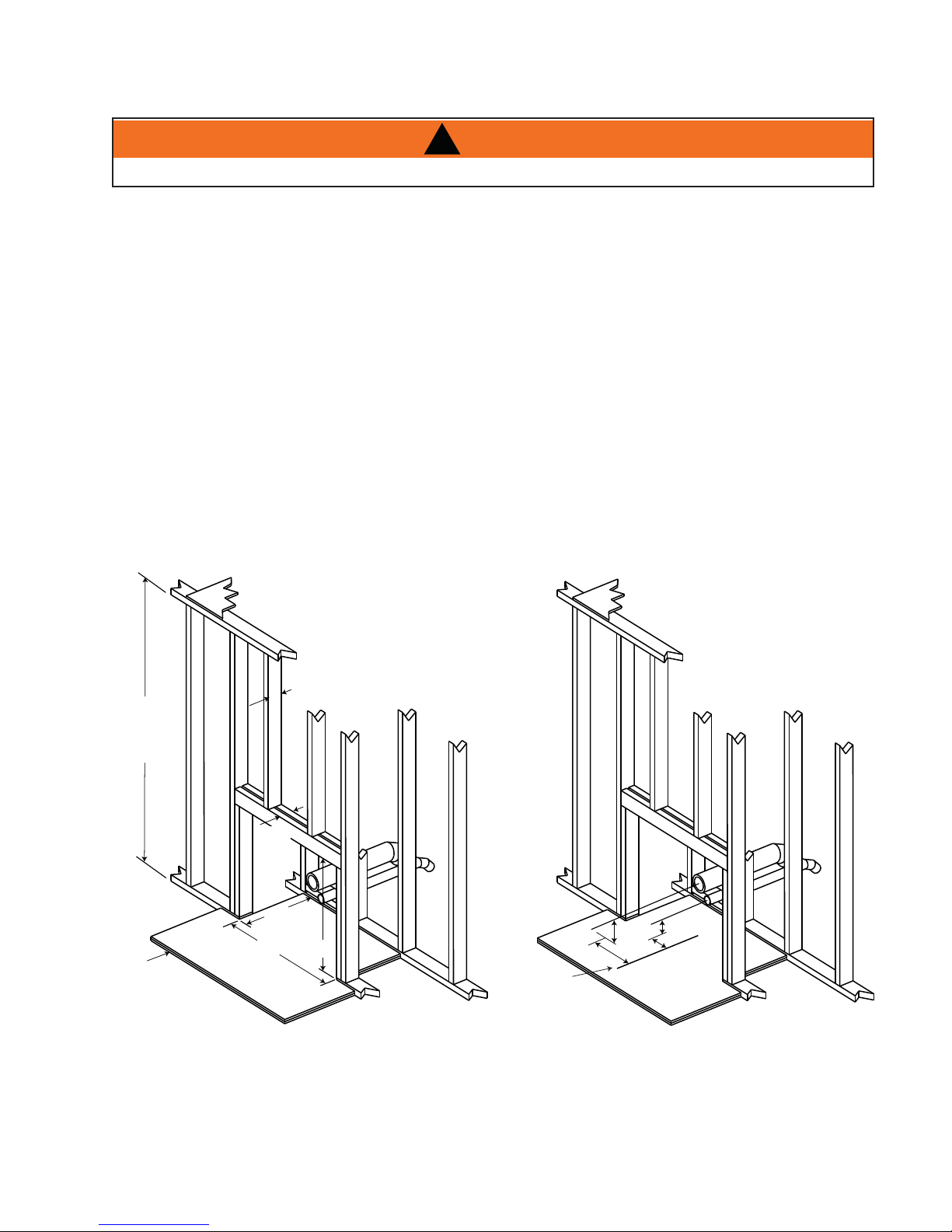
5.1 INSTALLATION INTO A COMBUSTIBLE ENCLOSURE
!
WARNING
OUTSIDE AIR IS MANDATORY FOR A COMBUSTIBLE BUILT-IN ENCLOSURE INSTALL.
When installing the insert as a "Built-in" appliance, it is important to maintain the clearances to combustibles,
see "MINIMUM CLEARANCE TO COMBUSTIBLES" section.
A non-combustible hearth must cover the fl ooring underneath, as well as, a minimum of six inches in front and
to both sides of the appliance.
A. Install fl oor protection.
B. Frame structure maintaining minimum clearances. Locate and frame openings for both the exhaust
and outside air. Outside air is mandatory for enclosure installations. See "OUTSIDE AIR" section.
C. Refer to vent manufacturer's installation instructions and to "GENERAL VENTING" section. Connect
the vent.Install fl ashing, see "FLASHING INSTALLATION" section.
D. Consideration must be taken during installation that removal of the insert is necessary for inspection
and annual maintenance. Install the vent cap.
3 1/2” MAX
40”
MINIMUM
ENCLOSURE
HEIGHT
3 1/2”
MAX
17”
Non
combustible
floor protection.
This protection must
offer an R value of 0.4 (two
layers of 1/2” thick cement board, total 1” with each layer rated with an
R value of 0.2).
For temperature requirements, the enclosure space around and
above the heater must be left unobstructed.
33”
27”
Centerline of
heater opening
7 1/8”
4 7/8”
1 7/8”
2”
W415-0865 / B / 05.26.11
Page 23
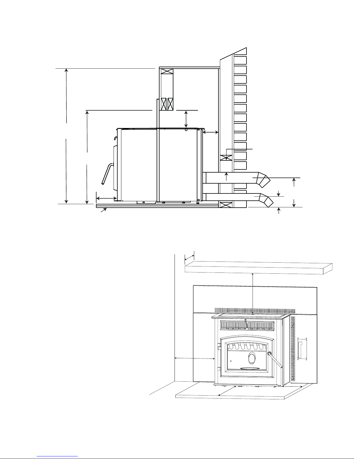
5.2 MINIMUM ENCLOSURE CLEARANCES
6 3/8”
MIN.
40” MIN.
27” MIN.
23
2” MIN.
3” all around (Refer to vent
manufacturer’s instructions)
6”
Non-combustible
floor protection
5.3 MINIMUM CLEARANCE TO COMBUSTIBLES
Side wall to appliance 8"
Mantel to top of appliance 8"
Top facing to appliance 6 3/8"
Side facing to appliance 6"
Floor protection* 6"*
* Floor Protection: Minimum 6" in front of door
and to either side.
10”
Side Wall
7 1/8”
1 7/8”
10” Mantel
8” MIN
8”
MIN
6”
6”
W415-0865 / B / 05.26.11
Page 24
24
5.4 MINIMUM MANTEL CLEARANCES
RISK OF FIRE, MAINTAIN ALL SPECIFIED AIR SPACE CLEARANCES TO COMBUSTIBLES. FAILURE
TO COMPLY WITH THESE INSTRUCTIONS MAY CAUSE A FIRE OR CAUSE THE APPLIANCE TO
OVERHEAT. ENSURE ALL CLEARANCES (I.E. BACK, SIDE, TOP, VENT, MANTEL, FRONT, ETC.) ARE
CLEARLY MAINTAINED.
WHEN USING PAINT OR LACQUER TO FINISH THE MANTEL, THE PAINT OR LACQUER MUST BE
HEAT RESISTANT TO PREVENT DISCOLOURATION.
16” MANTEL
14”
12”
10”
14”
12”
10”
8”
!
WARNING
73.1
5.5 ALCOVE INSTALLATION REQUIREMENTS (MINIMUM)
35”
30”
48”
STOVE
Minimum Alcove Dimensions
W415-0865 / B / 05.26.11
Page 25
6.0 FINISHING
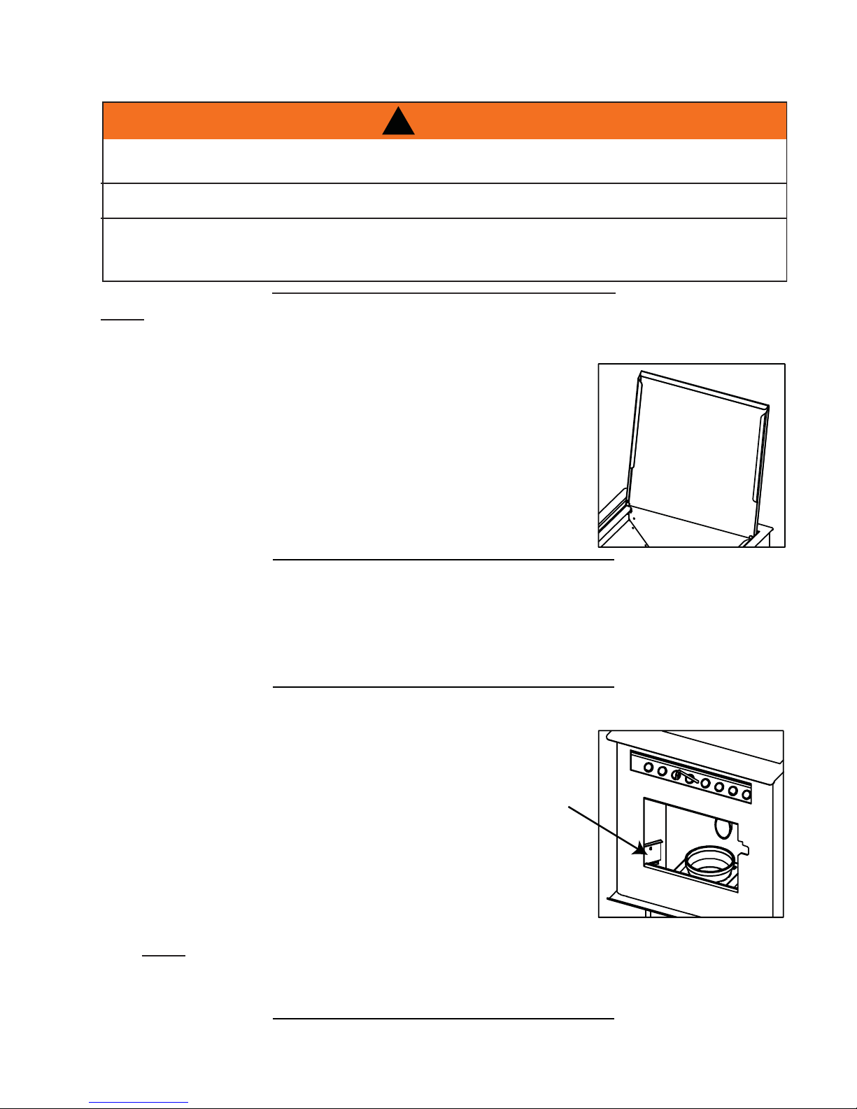
6.1 INSTALLING VIEWING DOOR
GLASS MAY BE HOT, DO NOT TOUCH GLASS UNTIL COOLED.
THE DOOR LATCHES ARE PART OF A SAFETY SYSTEM AND MUST BE PROPERLY ENGAGED. DO
NOT OPERATE THE APPLIANCE WITH LATCHES DISENGAGED.
BEFORE DOOR IS REMOVED TURN THE APPLIANCE OFF AND WAIT UNTIL APPLIANCE IS COOL TO
THE TOUCH. DOORS ARE HEAVY AND FRAGILE SO HANDLE WITH CARE.
The main viewing door has been boxed separate from the appliance, but MUST
be installed before burning the appliance.
A. Align the pins on the door to the bushing on the left side of the
appliance. Lower into place until both bushings touch.
!
WARNING
25
75.2
W415-0865 / B / 05.26.11
Page 26

26
6.2 DOOR HANDLE INSTALLATION
NOTE: DOOR MAY NOT BE AS
ILLUSTRATED
FRONT VIEW
DOOR
DOOR HANDLE
LATCH
LOCK
WASHER
NUT
DOOR
HANDLE
6.3 DECORATIVE INSET
SPRING
WASHER
SPACER
NOTE: Position of
door handle latch.
98.1
W415-0865 / B / 05.26.11
Page 27

6.4 FLASHING INSTALLATION
A. Secure the left fl ashing to the left side with the three screws provided. Repeat for the right side.
B. Side panels are attached to the fi rebox by the three magnets per side.
C. Lower the top panel, aligning the slots in the top panel with the holes in the side panel.
D. Secure the top panel by to the side panels with the screws and washers provided. NOTE: Make sure
the side panels are tight to the fi rebox before securing the screws.
E. The fl ashing can be adjusted forward and
backward by re-adjusting the fl ashing
along the magnets.
F. Slide trim over
fl ashing.
27
TRIM
RIGHT
SIDE
TOP
PANEL
LEFT
SIDE
LEFT
FLASHING
RIGHT
FLASHING
W415-0865 / B / 05.26.11
Page 28

28
7.0 WIRING DIAGRAM
DO NOT USE THIS APPLIANCE IF ANY PART HAS BEEN UNDER WATER. CALL A QUALIFIED
SERVICE TECHNICIAN IMMEDIATELY TO HAVE THE APPLIANCE INSPECTED FOR DAMAGE TO THE
RISK OF ELECTRICAL SHOCK OR EXPLOSION. DO NOT WIRE 110V TO THE VALVE OR TO THE
APPLIANCE WALL SWITCH. INCORRECT WIRING WILL DAMAGE CONTROLS.
ALL WIRING SHOULD BE DONE BY A QUALIFIED ELECTRICIAN AND SHALL BE IN COMPLIANCE
WITH LOCAL CODES. IN THE ABSENCE OF LOCAL CODES, USE THE CURRENT CSA22.1 CANADIAN
ELECTRIC CODE IN CANADA OR THE CURRENT NATIONAL ELECTRIC CODE ANSI/NFPA NO. 70 IN
ALWAYS LIGHT THE PILOT WHETHER FOR THE FIRST TIME OR IF THE GAS SUPPLY HAS RAN OUT,
WITH THE GLASS DOOR OPENED OR REMOVED.
!
WARNING
ELECTRICAL CIRCUIT.
THE UNITED STATES.
69.2
HIGH
LIMIT
YELLOW
YELLOW
WHITE
WHITE
CONVECTION
BLOWER
ORANGE
WHITE
POWER
CORD
BLACK
BLACK
WHITE
ORANGE
COMBUSTION
BLOWER
GREEN
RED
BLUE
IGNITOR
RED
WHITE
ORANGE
RED
HOPPER
SWITCH
RED
AUGER
MOTOR
RED
GREY
PURPLE
LOW LIMIT
VACUUM
SWITCH
YELLOW
BLACK
GREY
W415-0865 / B / 05.26.11
Page 29

8.0 OPERATING INSTRUCTIONS
8.1 PROPER PELLET LOADING
Before loading pellets into the hopper fi rst transfer the pellets from it’s original plastic bag to a metal bucket.
Keep in mind that the auger stops when the lid is opened. If the lid is opened for several minutes, the fi re may
extinguish.
NOTE: If the pellets are kept in the plastic bag, the bag may come in contact with the appliance causing
the bag to melt and the pellets to spill.
DO NOT load pellets into the hopper if they have been exposed to moisture. Moisture can cause pellets
to swell and cause blockage in the feed system. Thoroughly dry pellets before placing into hopper.
8.2 PRE-START CHECK
Before installing this appliance we recommend a “PRE-BURN” inspection to help burn off the odours that are
associated with the fi rst burn. If possible, move the appliance outside and add approximately 5 lbs of pellets
into the hopper. Plug the power cord into a typical wall receptacle.
The appliance is equipped with a control board that has been shipped in manual mode.
When fi rst starting a new pellet appliance, or when you completely empty the hopper of pellets you can press
and hold the prime button to get the pellets into the burn pot quicker.
● Slide the "ON/OFF" button to "ON":
This starts the ignition cycle.
29
47.10
● The auger comes on and runs for approximately 3 minutes.
● The igniter comes on and will stay on until proof of fi re determined by the appliance temperature.
● At anytime during the ignition cycle, once proof of fi re is met, the appliance goes into normal operating
mode.
NOTE: Flame should appear in the burn pot within 3 to 7 minutes from commencing the ignition cycle.
The ignition cycle should end in approximately 12 to 15 minutes. At this point adjustments to feed rate
can be made or the appliance will revert to the previous setting. If proof of fi re is not established in 15
minutes, the appliance will shut down and will need to be turned back on again. If the appliance shuts
down, empty the pellets from the burn pot into an empty non-combustible container and restart. Never
empty pellets from burn pot back into hopper.
8.3 LIGHTING APPLIANCE MANUALLY
!
APPLIANCE MAY BE HOT.
OTHER THAN PLACING A HANDFUL OF PELLETS IN THE BURN POT FOR LIGHTING MANUALLY,
NEVER FEED PELLETS THROUGH THE GLASS VIEWING DOOR. AN "OVERFIRE" CONDITION
COULD OCCUR, IF MORE PELLETS ENTER THE FIREBOX THAN WHAT THE FEED TUBE CAN
DELIVER. PELLETS MUST ONLY BE BURNED WITHIN THE BURN POT.
WARNING
NEVER USE GASOLINE TYPE LANTERN FUEL, KEROSENE, CHARCOAL LIGHTER FLUID, OR
SIMILAR LIQUIDS TO START OR ‘FRESHEN UP’ A FIRE IN THIS APPLIANCE. KEEP ALL SUCH
LIQUIDS WELL AWAY FROM THE APPLIANCE WHILE IT IS IN USE.
Your appliance can be lit manually without using the automatic igniter by following the procedure below.
• Press the ON / OFF button.
• Place a “handful” of pellets into the burn pot.
• Cover with a small amount of approved (non-volatile) fi re starter gel.
• Light fi re starter with a match and close the viewing door.
47.11
W415-0865 / B / 05.26.11
Page 30

30
8.4 LIGHTING INSTRUCTIONS
After fi lling the hopper with pellets, switch the control to manual so that you have full control of the appliance
until you have familiarized yourself with its functions.
Do not try to operate your appliance with the viewing door or hopper lid open. Safety switches will disable the
pellet feed auger.
A. Slide the "ON/OFF" button "ON" to initiate the ignition cycle.
B. Once the ignition cycle has ended (approximately 12 to 15 minutes) adjustments can be made to the
control.
8.5 CONTROLS
INDICATOR LIGHTS
Solid
- Indicates set feed rates.
Flashing
- Indicates an operation failure.
HEA T ADJUSTMENT
Increases or decreases the heat
level.
PRIME
Speed feeding of pellets into the burn
pot.
OPERATING MODE
Sets the appliances operating
mode.
ON / OFF
Used to turn the appliance on or
off.
W385-0500
AUTO / MANUAL
This switch is used to select the operating mode.
MANUAL: Sliding the switch down to manual will allow you to manually select the heat level. In
manual mode the appliance will run at your desired settings indefi nitely, until you manually turn the ap-
pliance off or the appliance runs out of pellets.
AUTO: Slide the switch to the top position (AUTO). The auto mode operates using either a wall or a
remote control thermostat. If the thermostat does not call for heat in a 60 minute period the appliance
will turn off completely. When the thermostat does call for heat, it will initiate an ignition cycle.
ON / OFF
Use this button to turn the appliance on and off.
HEAT LEVEL
Pressing the heat level button will increase the heat level one setting. Pressing the heat level button down will
decrease the heat level one setting. The red lights at the top left of the control will indicate the heat setting 1
through 3.
PRIME
Pressing and holding this button will turn the auger continuously which increases the feed of pellets into the
burn pot. This is convenient when using the appliance for the fi rst time or when you have completely emptied
the hopper and need to restart the appliance.
W415-0865 / B / 05.26.11
Page 31

8.6 CONTROL ADJUSTMENT
FEED TRIM
Both the combustion fan speed and the feed rate have been factory set but may need to be adjusted (trimmed)
on site. Due to the variables (i.e. vent size, length and pellet quality), the factory settings may not be ideal for
every installation. To help keep the fl ame from extinguishing on the minimum heat level, the feed rate can be
trimmed when in normal operation (after the 15 minute ignition cycle). Depress and hold the prime button while
you push the heat level button. This will slightly increase the amount of fuel being fed into the burn pot. When
trimming the feed rate for the fi rst time, the LED’s will display the (#3 and #1 light) indicating that the appliance
is factory set to (#2) with the ability to increase up one level (#3) or decrease down one level (#1) the length
of time between the prime cycle. NOTE: The light that isn't on indicates the trim setting of the appliance,
trimmed down, neutral or trimmed up.
BLOWER TRIM
Similar to the feed rate, it may be necessary to trim the speed of the
combustion blower. Due to specifi c installations, it may be necessary
to increase or decrease the amount of air moving through the burn pot
to achieve maximum effi ciency. In order to adjust the blower trim you
need access to the back of the control panel. Start by either removing
the side panel (pedestal) or behind the fl ashing (insert), using a small
screw driver turn the screw to adjust the blower (clockwise to increase/
counter-clockwise to decrease) and reinstall the panel / fl ashing that was
removed. NOTE: It is recommended to adjust the blower trim prior to
installing the insert.
8.7 INSTALLING A THERMOSTAT
31
BLOWER
TRIM
An optional millivolt thermostat is available to help keep the room temperature constant.
NOTE: The thermostat must be installed by a qualifi ed installer.
● Disconnect the power supply.
● Remove the right side panel to gain access to the rear of the
control panel.
● Strip and connect the two thermostat wires to the two screw terminals on the back of the control panel.
NOTE: The control must be in AUTO to control the appliance with a thermostat.
8.8 SHUTDOWN INSTRUCTIONS
Slide the "ON/OFF" button to "OFF". Your appliance will cycle down and the blower will remain operating until
your appliance has cooled.
SCREW
TERMINALS
W415-0865 / B / 05.26.11
Page 32

32
9.0 NORMAL OPERATING SOUNDS
EXHAUST BLOWER
The flow of exhaust gases may
create a low-pitched hum. As
the pellet feed rate is altered
this sound will change.
CONVECTION BLOWER
A low hum might be heard due to the high
efficiency fan, especially on high.
AUGER MOTOR
An irregular buzz of the motor
running might be heard when
pellets are being fed.
Expansion / contraction noises during heating up and cooling down cycles are normal and are to be
expected.
W415-0865 / B / 05.26.11
BURN POT
A light clicking sound
might be heard as the
pellets are fed into
the burn pot.
Page 33
10.0 MAINTENANCE
10.1 DAILY (WHENEVER USING THE APPLIANCE)
!
WARNING
THE FRONT OF THE APPLIANCE BECOMES VERY HOT DURING OPERATION. LET THE APPLIANCE
COOL COMPLETELY BEFORE CONDUCTING SERVICE.
10.1.1 DISPOSAL OF ASHES
Ashes should be placed in a metal container with a tight fi tting lid. The container should be placed on a non-
combustible fl oor, well away from combustible materials, pending fi nal disposal. If ashes are disposed of by burial
in soil or otherwise locally dispersed, they should be retained in the closed container until all cinders are thoroughly
cooled.
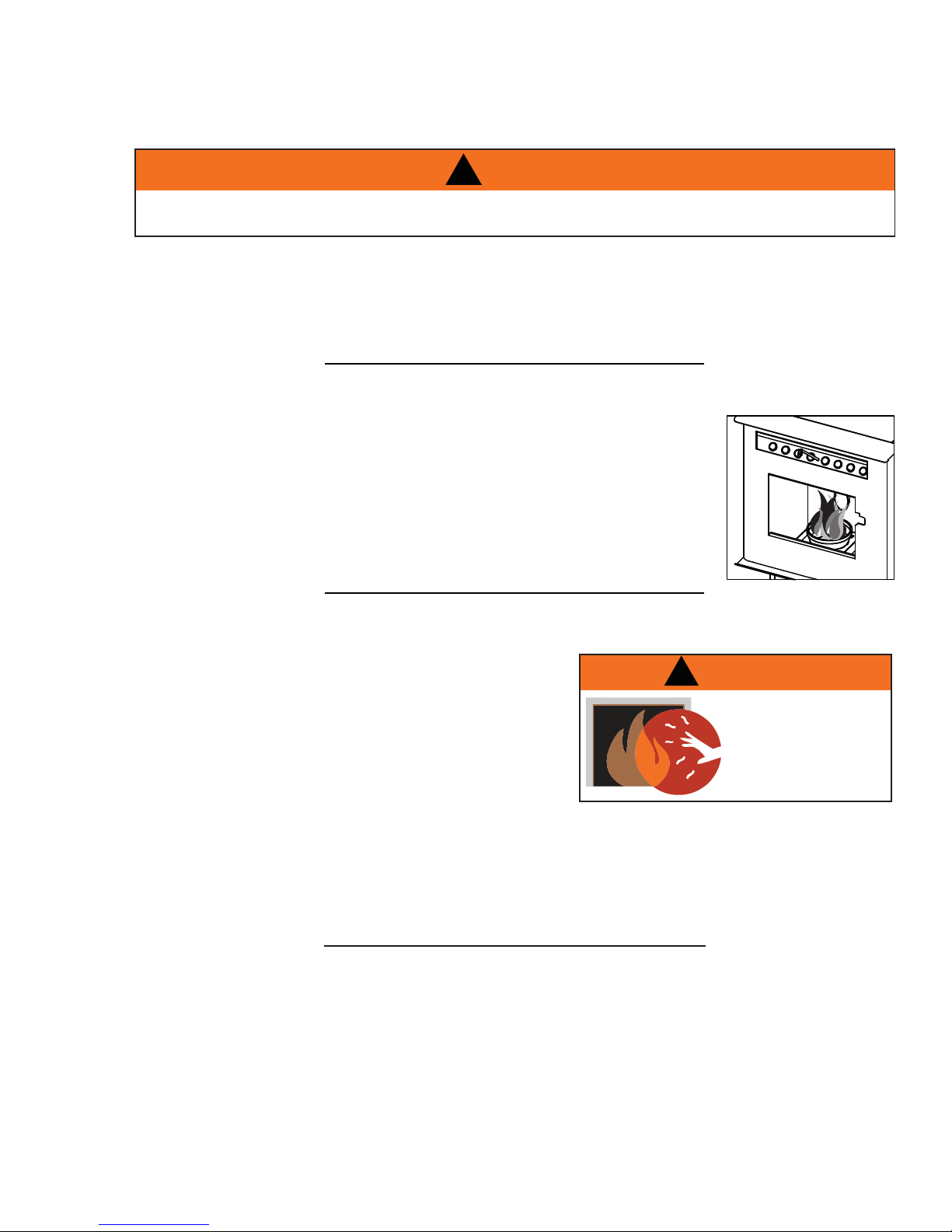
10.1.2 INSPECT THE BURN POT
When burning, the fl ames should be bright orange with embers jumping from the
burn pot. If not see “MAKE SURE PELLETS ARE NOT PILING UP” or “CLEANING
THE BURNPOT” sections.
33
40.2
10.1.3 CARE OF GLASS
If the glass is not kept clean permanent discolouration and / or
blemishes may result. Normal operation of your pellet appliance
will produce a build-up on the glass that should be wiped off
daily. However, poor quality pellets or extended burning on the
low setting will cause the glass to “smoke up” faster.
Refer to “REPLACEMENT PARTS” section to fi nd out what this
product is equipped with. Use only replacement glass available
from your Authorized dealer.
DO NOT CLEAN GLASS WHEN HOT!
If necessary, clean the glass with a soft cloth or paper towel. You could use “wood stove” glass cleaner to
remove heavy build-up.
Do not operate the appliance with broken glass, as leakage of fl ue gases may result.
40.3A
!
WARNING
HOT GLASS WILL
CAUSE BURNS.
DO NOT TOUCH GLASS
UNTIL COOLED.
NEVER ALLOW CHILDREN
TO TOUCH GLASS.
5.2
W415-0865 / B / 05.26.11
Page 34

34
10.1.4 CLEANING THE HEAT EXCHANGER TUBES
!
WARNING
THE FRONT EDGE OF THE HOPPER LID BECOMES VERY HOT, DO NOT TOUCH THE AREA BELOW
THE HANDLE.
THIS ROD BECOMES VERY HOT DURING OPERATION. WAIT UNTIL APPLIANCE HAS COOLED
COMPLETELY OR WEAR HEAT RESISTANT GLOVES WHEN CLEANING OR HANDLING THIS
APPLIANCE.
With the appliance cool (or wearing heat resistant gloves),
slide the heat exchange cleaner rod up and down several
times to prevent the build up of ash on the heat exchange
tubes.
Keep the viewing door closed so the fl y ash does not enter the
room.
NOTE: More frequent cleaning may be required depending
upon pellet quality.
HEAT
EXCHANGE
CLEANER
ROD
10.1.5 MAKE SURE PELLETS ARE NOT PILING UP
If the pellets build up over the burn pot, turn the pellet feed switch to “OFF”. If
the fl ames seem to be coming only from the sides, or are orange/black, turn
the appliance off and check for build up of pellets.
The most likely causes are:
A. Feed rate has been set to maximum for an extended period of time.
Turn feed rate to optimum.
B. The door, glass, or ash pan is open or has an air leak.
C. The burn pot requires cleaning.
D. The exhaust system requires cleaning.
E. The appliance requires adjustment (trim feed rate and blower).
F. Poor pellet quality
40.4A
40.5B
W415-0865 / B / 05.26.11
Page 35
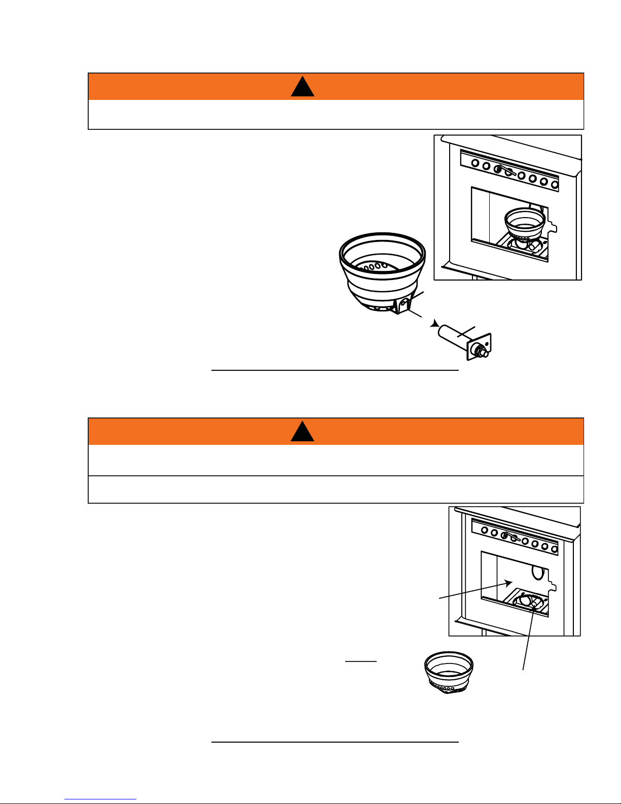
10.1.6 CLEANING THE BURN POT
MAKE CERTAIN THE HEATER HAS FULLY COOLED (APPROXIMATELY 25 MINUTES) BEFORE
OPENING THE DOOR AND
To clean the burn pot, open the door and knock away any debris on the
burn pot. If severely clogged, remove the burn pot to gain better access.
If removing the burn pot set aside on a non-combustible surface. Once
removed, discard all material that has accumulated in the burn pot.
Make certain that all openings are clear of any build up of ash from the
ledge below the burn pot.
Re-install the burn pot ensuring it sits level in the
appliance. Also must ensure the ignitor and the burn
pot locating notch line up when reinstalling the burn
pot.
!
WARNING
35
LOCATING
NOTCH
IGNITOR
10.2 BI-WEEKLY (OR EVERY 10 BAGS OF PELLETS)
10.2.1 VACUUM FIREBOX
!
WARNING
THE FIREBOX BECOMES VERY HOT DURING OPERATION. LET THE APPLIANCE COOL COM-
PLETELY BEFORE CONDUCTING SERVICE.
NEVER VACUUM HOT EMBERS.
The more frequently you clean out the fl y ash, the more effi cient your appliance
will burn.
A. Open the viewing door.
B. Lift the burn pot out and set aside on a non-combustible surface.
C. Vacuum out the fi rebox. Do not use a household
vacuum to clean the appliance. We recommend that
you use a shop vacuum that is equipped with a fi ne
dust fi lter or a vacuum specifi cally made for ashes and soot.
Using a vacuum which is not equipped with a fi ne dust fi lter may
clog and disperse fl y ash and soot into the room. NOTE: The
appliance must be completely out before you vacuum the
appliance. Live pellets, if sucked into the vacuum will light
the vacuum on fi re and may ultimately cause a house fi re.
FIREBOX
40.6A
AIR
HOUSING
Re-install the burn pot ensuring it sits level in the appliance. Also must ensure the ignitor and the burn pot
locating notch line up when reinstalling the burn pot.
40.18
W415-0865 / B / 05.26.11
Page 36
36
10.3 SEMI-ANNUALLY (OR EVERY TWO TONS OF PELLET)
!
WARNING
THE FIREBOX BECOMES VERY HOT DURING OPERATION. LET THE APPLIANCE COOL COMPLETELY BEFORE
CONDUCTING SERVICE.
DISCONNECT THE POWER CORD PRIOR TO CONDUCTING SERVICE.
THE FOLLOWING SECTION DETAILS EXTENSIVE MAINTENANCE PROCEDURES. WE STRONGLY SUGGEST
THESE ITEMS BE CARRIED OUT BY A TRAINED SERVICE TECHNICIAN, POSSIBLY BY A SERVICE AGREEMENT
SET UP WITH YOUR DEALER.
NOTE: More frequent cleaning may be required depending on pellet quality.
10.3.1 VACUUM HOPPER
The more frequently you clean out the fl y ash, the more effi cient your
appliance will burn.
A. Operate the appliance until the pellets run out, then open the hopper
and vacuum out the entire hopper.
40.15
The dust and any other debris near the bottom should be removed to
prevent excessive build-up.
10.3.2 SOOT AND FLY ASH FORMATION
The products of combustion will contain small particles of fl y ash. The fl y ash will collect in the exhaust venting
system and restrict the fl ow of the fl ue gases. Incomplete combustion occurs during startup, shutdown, or
incorrect operation of the room appliance will lead to some soot formation which will collect in the exhaust
venting system. The exhaust venting system should be inspected at least once every year to determine if
cleaning is necessary.
10.3.3 CLEAN THE VERTICAL EXHAUST DUCT
A. Pivot the viewing door wide open.
B. Remove the one screw on each exhaust port located
on either side of the fi re box. Remove the exhaust port
doors and set aside on a non-combustible surface.
Insert a vacuum into the exhaust port holes and remove as
much fl y ash as possible from behind the left and right exhaust
manifolds. Do not use a household vacuum to clean the
appliance. We recommend that you use a shop vacuum that is
equipped with a fi ne dust fi lter or a vacuum specifi cally made
for ashes and soot. Using a vacuum which is not equipped with
a fi ne dust fi lter may clog and disperse fl y ash and soot into the
room. NOTE: The appliance must be completely out before you vacuum the appliance. Live pellets, if
sucked into the vacuum will light the vacuum on fi re and may ultimately cause a house fi re.
40.8B
40.9
EXHAUST
PORT
Once clean, replace the exhaust port doors and secure with the screws.
W415-0865 / B / 05.26.11
40.17A
Page 37
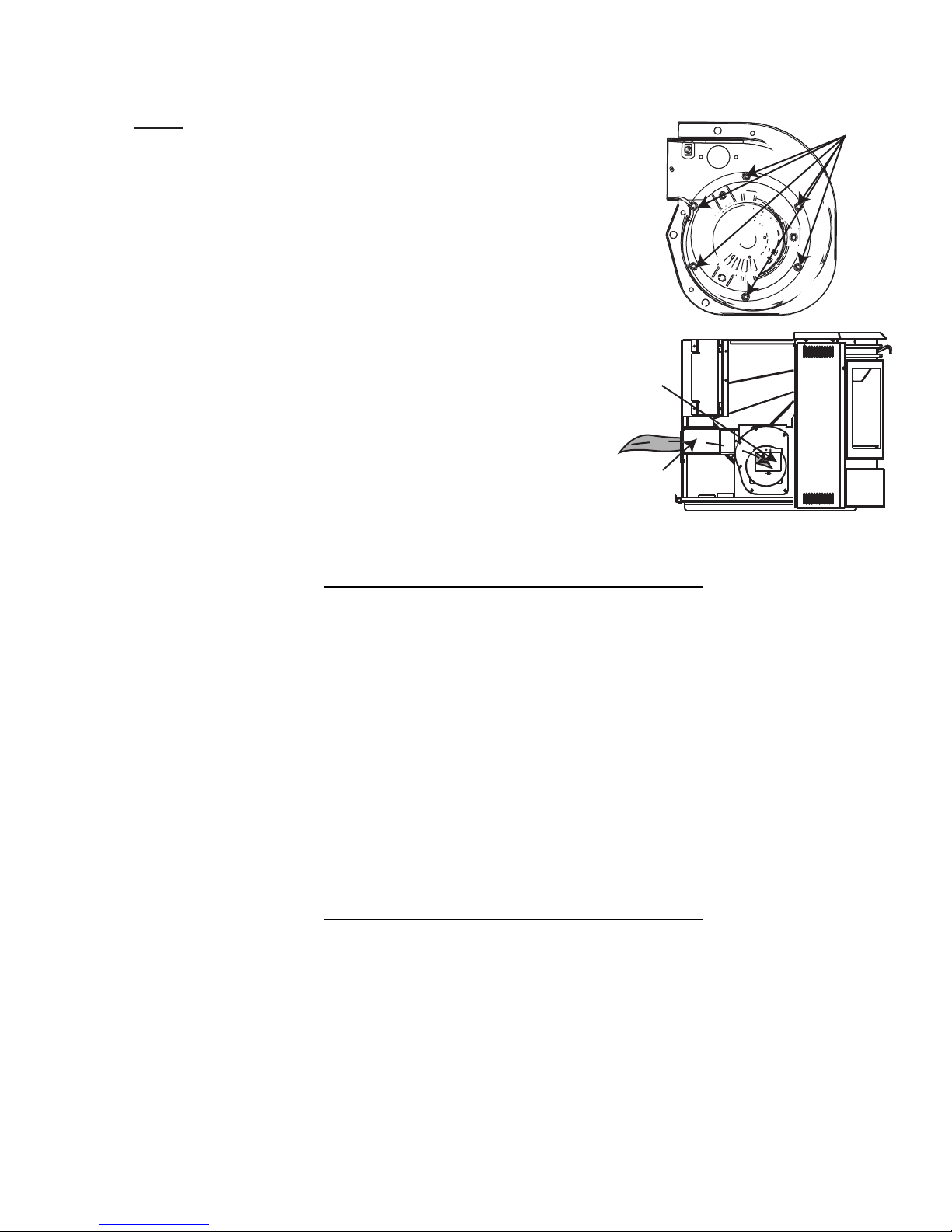
10.3.4 CLEAN THE EXHAUST BLOWER
37
NOTE: Do not attempt this maintenance without a
replacement exhaust blower motor mounting gasket.
A. Remove the six nuts holding the exhaust blower motor
in place.
B. Pull the motor out being careful not to damage the
wiring, unplug the two wires that are connecting the
motor and gently set aside. (The pieces of gasket may
be discarded.
C. Start by cleaning the exhaust tube by feeding a brush
or rag through the inside of the tube and out the
exhaust blower housing.
EXHAUST
D. Vacuum out the exhaust ports and the blower housing.
E. With a bristle brush vacuum, clean the blades of the
motor.
F. Place the new exhaust blower mounting gasket around
the screw holes being very careful not to tear it.
G. Re-attach the wiring to the motor and place it back on to the housing, taking care that the side of the
motor does not tear the gasket and then re-attach the nuts.
BLOWER
EXHAUST
HOUSING
40.11
NUTS
10.3.5 CHECK ALL SEALS
Check for air leaks around the door, glass, and ash pan and replace gaskets as required.
Air leaks into the fi rebox will decrease the appliance’s performance greatly, leading to excessive soot,
ineffi cient burning, and may even cause a malfunction.
Test the door seal by shutting the door on a piece of paper in various locations. If the paper can be easily slid
out, air may be leaking around the door seal. Carefully inspect the door gasket and door catch.
Inspect the door gasket to make sure it is fully attached. Appliance gasket cement can be used to re-attach if
necessary. If the door gasket is worn or fl attened, replace.
Check the door to make sure it latches correctly. The latch should engage with a slight amount of resistance,
yet not be too diffi cult.
If the glass is cracked, replace.
40.12
W415-0865 / B / 05.26.11
Page 38
38
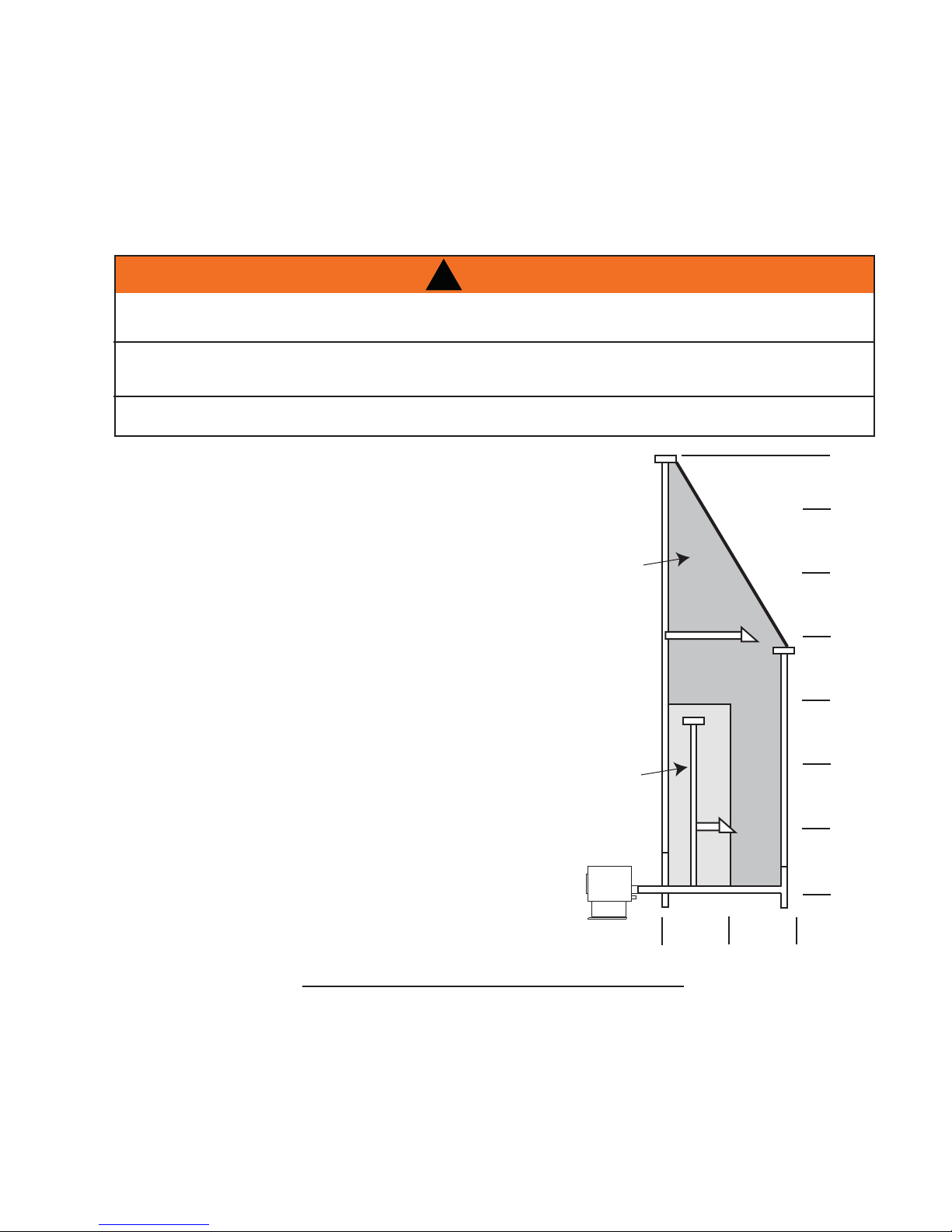
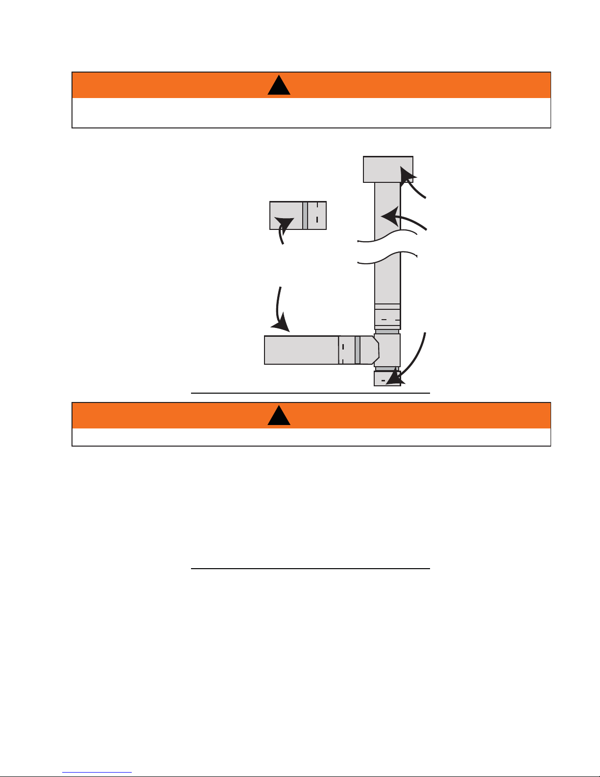
10.3.6 CLEAN THE VENT
WHENEVER ANY PORTION OF THE PELLET VENT IS DISCONNECTED, THE JOINTS MUST BE
RE-SEALED WITH RTV 500°F SILICONE SEALANT.
!
WARNING
Vent system should be cleaned
using chimney sweep brushes. We
recommend this be done by a qualifi ed
chimney sweep.
Flyash will deposit
along sections that
are horizontal
10.4 IN THE EVENT OF A JAMMED AUGER
!
WARNING
DISCONNECT THE POWER CORD PRIOR TO CONDUCTING SERVICE.
Make sure the cap is free of
debris (especially if it has a
screen that could become
blocked).
Check the vent sections for
creosote accumulation
(indicating a poorly burning
stove). Accumulation
greater than 1/4" must be
removed.
On vertically vented
systems, the dirtiest portion
is often the point where the
vent turns upwards (ex. the
"Tee"). Remove the clean
vent cover and inspect and
clean if necessary.
40.13
Occasionally damp fuel or foreign objects could get jammed in the auger screw. When this occurs it will be
necessary to empty the hopper and/or remove the auger screw from the hopper assembly.
Start by emptying the pellets from the hopper. Sometimes the object causing the auger screw not to turn will be
visible once the hopper has been emptied. If it is necessary to remove the auger screw start by removing both
of the side panels and the rear panel. Locate the auger motor, remove the set screw that secures the motor to
the auger screw. Remove the two hex bolts from the auger housing which will allow the auger screw to slide out.
After you have removed the shaft, inspect it for bent fl ights, burrs, or broken welds. Remove any foreign material
that might have caused the jam. Also, check the auger tube for signs of damage such as burrs, rough spots, or
grooves cut into the metal that could have caused a jam.
40.14A
W415-0865 / B / 05.26.11
Page 39

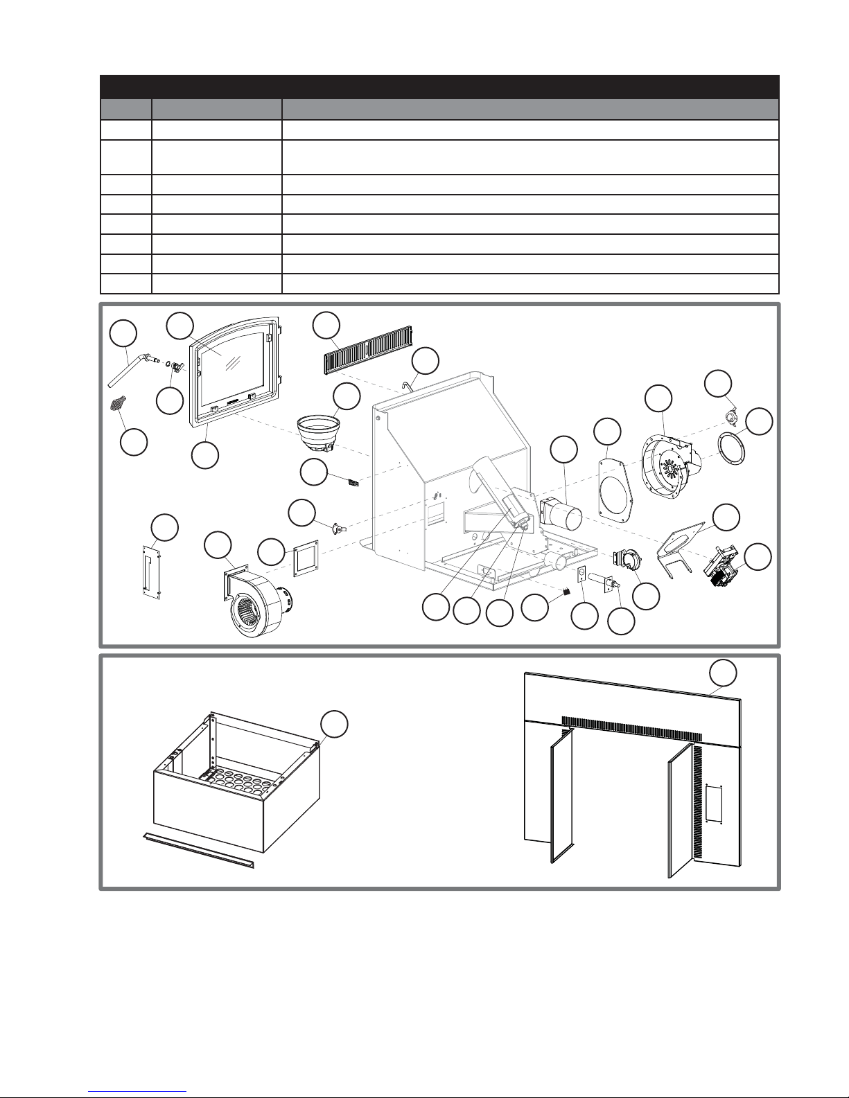
11.0 REPLACEMENTS
Contact your dealer or the factory for questions concerning prices and policies on replacement parts. Normally
all parts can be ordered through your Authorized dealer / distributor.
FOR WARRANTY REPLACEMENT PARTS, A PHOTOCOPY OF THE ORIGINAL INVOICE WILL BE
REQUIRED TO HONOUR THE CLAIM.
When ordering replacement parts always give the following information:
• Model & Serial Number of appliance
• Installation date of appliance
• Part number
• Description of part
• Finish
* IDENTIFIES ITEMS WHICH ARE NOT ILLUSTRATED. FOR
FURTHER INFORMA TION, CONTACT YOUR AUTHORIZED DEALER.
COMMON COMPONENTS
REF PART NO. DESCRIPTION
1 W660-0052 LOW LIMIT SWITCH 140°F (60°C)
2 W660-0055 HIGH LIMIT SWITCH 200°F (93°C)
3 W660-0056 VACUUM SWITCH
4 W325-0043 HANDLE, SPRING
5* W195-0004 POWER CORD
6 W435-0019 AUGER MOTOR
7 W062-0025 CONVECTION BLOWER (TPS35)
7 W062-0030 CONVECTION BLOWER (TPI35)
8 W062-0027 COMBUSTION BLOWER
9 W290-0111 COMBUSTION BLOWER MOUNTING GASKET
10 W290-0120 COMBUSTION BLOWER MOTOR MOUNTING GASKET
11 W290-0113 CONVECTION BLOWER GASKET
12 W570-0107 AUGER SCREW
13 W190-0035 CONTROL
14 W105-0012 NYLON BUSHING
15 W500-0501 AUGER RETAINER C/W SCREW
16 W555-0061 SCRAPER ROD
17* W750-0227 HARNESS WIRE
18* W385-0487 TIMBERWOLF® LOGO
19* W562-0004 GLASS GASKET (3/4" CHANNEL)
20 W720-0139 EXHAUST TUBE
21 W357-0007 IGNITOR
22
23
24*
25
26*
27*
28
29
30* W430-0013 DOOR MAGNET ASSEMBLY
31 W325-0018 DOOR HANDLE
32 W320-0002 DOOR HANDLE LATCH
33* W285-0002 FUSE, 2 AMP
W135-0320 CAST, BURN POT
W290-0119 IGNITION GASKET
W460-0004 RECEPTACLE
W300-0131 GLASS
W562-0010 DOOR GASKET (3/8" ROPE)
W660-0083 SWITCH, HOPPER
W715-0843 DECORATIVE INSET
W225-0258 DOOR, BLACK
39
!
WARNING
FAILURE TO POSITION THE PARTS
IN ACCORDANCE WITH THIS
MANUAL OR FAILURE TO USE ONLY
PARTS SPECIFICALLY APPROVED
WITH THIS APPLIANCE MAY
RESULT IN PROPERTY DAMAGE OR
PERSONAL INJURY.
41.1
W415-0865 / B / 05.26.11
Page 40
40
ACCESSORIES
REF PART NO. DESCRIPTION
34* 114KT OUTSIDE AIR KIT - 5 FT (2" DIA.)
35 TPHE HOPPER EXTENSION (INCREASES HOPPER CAPACITY FROM 45 LBS TO 100 LBS
PELLETS) STOVE ONLY
36 TI800 FLASHING KIT (INCLUDES FLASHING/SURROUND, SMALL HOPPER DOOR)
37* F50 THERMOSTATIC REMOTE
38* F50-6 BULK THERMOSTATIC REMOTE
39* 270 PAINT, THURMALOX - BLACK
40* F40 ON/OFF REMOTE
41* F40-6 BULK ON/OFF REMOTE
31
4
32
13
25
29
7
11
2
31
28
35
22
16
12
14
15
25
20
23
9
1
8
10
23
6
3
21
36
W415-0865 / B / 05.26.11
Page 41

12.0 TROUBLESHOOTING
!
WARNING
TURN OFF THE ELECTRICAL POWER BEFORE SERVICING THE APPLIANCE.
APPLIANCE MAY BE HOT, DO NOT SERVICE UNTIL APPLIANCE HAS COOLED.
DO NOT USE ABRASIVE CLEANERS.
WHEN CHECKING CONNECTIONS, INSTALLING JUMPER WIRES (FOR TEST PURPOSES ONLY) OR
REPLACING COMPONENTS, UNPLUG APPLIANCE FROM THE RECEPTACLE TO PREVENT ELECTRI-
CAL SHOCK OR DAMAGE TO THE COMPONENT.
NOTE: Many of the following tests will require that the side panels are removed from the appliance
or the insert be removed from its cavity to access the components. Before troubleshooting always
confi rm that all components are clean and free of ash build up.
PROBLEM SOLUTION
The appliance will
not start.
Check the vacuum
switch.
Check the ignitor
switch.
Smoke in the
room.
The exhaust
blower is not
operating.
- Make certain there is power to the outlet and that the appliance is plugged in.
- Hopper lid must be closed.
- The appliance ran out of fuel while set on ‘AUTO’. Appliance must be turned ‘OFF’
and set to ‘MANUAL’ to ‘AUTO’ if desired.
- Press ‘PRIME’ on control panel to feed pellets into burnpot until you see pellets start
to drop into the burpot.
- Start the appliance. If the appliance fails to start, unplug the appliance.
- With the appliance unplugged, examine all connections. Make sure no exposed wires
are touching the appliance (except the chassis ground wire) and that they are all
fi rmly connected.
- Check the manual reset hi limit switch.
- Check the stability and placement of connections against the wiring diagrams in this
manual.
- Check that the burn pot is positioned properly.
- The auger shaft may be jammed. For more information see “IN THE EVENT OF A
JAMMED AUGER” section.
- Blockage in igniter tube or inlet for igniter tube. Find the igniter housing on the back
side of the fi re wall. The air intake hole is a small hole located on the side of the
housing. Make sure it is clear. Also, look from the front of the appliance to make sure
there is not any debris around the igniter element inside of the igniter housing.
- Ensure the burnpot is seated completely into the burner housing.
- Defective igniter. Put power directly to the igniter. Watch the tip of the igniter from the
front of the appliance. After about 2 minutes the tip should glow. If it does not, the
igniter is defective.
- The control board might not be sending power to the igniter. Check the voltage going
to the igniter during startup. It should be a full current (115 volts). If the voltage is lower
than full current, check the wiring. If the wiring checks good, the board is defective.
- Contact your local dealer for service.
- Check all gasket seals.
- Check that the vent connections are sealed.
- Power failure.
- Appliance has failed to reach 140°F within 15 minutes and the blower has shut off.
- Remove the left side access panel and check all connections against the wiring
diagram. For the insert remove from cavity.
- Apply 115V AC directly to the exhaust blower and if the motor does not run, replace
the blower.
- If the motor runs, have a dealer check the wire harness.
- See “The appliance will not operate when hot” section
- Contact your local dealer or a certifi ed technician for service.
41
42.15C
W415-0865 / B / 05.26.11
Page 42

42
A
PROBLEM SOLUTION
The ignitor will not light
the pellets however
everything else in the
appliance operates.
The auger motor is not
functioning normally.
The appliance will not
operate when hot.
The appliance will not
turn off.
The 200°F (93°)
high limit temperature
sensor has tripped.
The convection blower
is not functioning
normally.
- Poor quality or damp pellets take longer to light.
- Push the burn pot back against the ignitor tube making sure the ignitor lines up to
the hole in the burn pot.
- Check igniter function.
- Hopper lid must be closed.
- Make certain the exhaust blower is operating.
- Check the condition of the vacuum hose (located on the left side of the
appliance). Should not be cracked or torn.
- Check the manual reset button on the 200°F (93°C) temperature sensor. Before
re-setting the red button, check for the cause of the over-heating.
- Check that the auger set screw is tight and not slipping.
- If the auger still does not work, then apply 115V AC directly to the auger motor. If
it still does not work, replace it.
- Check the auger by bypassing the 200°F (93°) temperature sensor with a jumper
wire. If auger works, replace the sensor.
- The auger shaft may be jammed. For more information see “IN THE EVENT OF
JAMMED AUGER” section.
- Check the vacuum sensor by placing a jumper wire between the grey wire and
the red wire that are attached to the sensor. If the auger works, test to see if the
exhaust blower is producing enough vacuum (may require cleaning).
- If not, replace the vacuum sensor.
- GENERAL
- Check the hopper for fuel.
- Different vent confi gurations may cause excessive air to consume the fi re
too quickly before the next drop of fuel. Therefore leaving the fuel completely
unburned in the burn pot and will cause the fuel to burn cold and very slowly. Fuel
also may build up and smother the fi re.
- NOTE: The appliance may require a change to the vent system or
installation of fresh air to correct air to fuel ratio problems.
- Combustion blower failure may occur because it is not turning fast enough to
generate the proper vacuum in the fi re box. Do a visual check to see if the motor
is turning.
- Check vacuum levels in the exhaust channel by bypassing the vacuum switch,
then remove the vacuum hose from vacuum switch. When checking the vacuum
exhaust place the open end of the vacuum hose on the gauge (readings must be
above 0.10” W.C. on low fi re). Ensure blower blades are clean.
- NOTE: if the motor fails to reach a 0.10” W.C., then replace the combustion
blower.
- Poor quality fuel may not produce enough heat to keep the appliance burning or
operational.
- If the exhaust temperature sensor fails try bypassing the sensor located on the
exhaust blower. If the appliance operates properly, the appliance may require
cleaning or a new sensor. Contact your local deal for service.
- Disconnect one of the brown wires from the exhaust temperature sensor and if
the appliance continues to operate, contact your local dealer for service.
- Clean any dust off the windings and blower blades. If cleaning the blower does
not help, the blower may be defective.
- Contact your local authorized dealer / distributor.
- Using the wiring diagram, compare all the connections between the control and
the convection blower.
- If the convection motor will not run, apply 115V AC to the motor directly. Replace
the control if the motor runs. The convection blower has failed if the motor does
not run. Replace the blower.
- The convection blower is overheating and tripping the high limit switch. Try
lubricating the convection blower. Also, clean any dust off of the windings and
blower blades. If oiling the blower does not help, the blower may be defective.
42.15_2C
W415-0865 / B / 05.26.11
Page 43

PROBLEM SOLUTION
The appliance
keeps going out.
Excessive carbon
build up in the
fi rebox, low heat
output.
Appliance is
burning dirty and
lazy.
The low limit
temperature sensor
has tripped.
Check that
your low burn is
consistent.
The vacuum
switch has been
tripped.
- Due to different installation set ups, length and size of venting and fuel quality, the
low feed setting from the factory will not always be correct. It may be necessary to
experiment with feed rate vs air control.
- If the appliance goes out and leaves fresh unburned pellets or cigarette-like ashes in
the burn pot, the fi re is going out before the appliance shuts off.
- Check to see if the appliance needs a more complete cleaning as well as the burn
pot, venting, etc...
- Was there a power failure?
- Trim feed rate and exhaust blower speed.
- If the appliance goes out and there are no pellets in the burn pot, the auger may be
slipping. See “THE AUGER MOTOR WILL NOT FUNCTION NORMALLY” and “THE
EXHAUST BLOWER WILL NOT FUNCTION NORMALLY” section.
- Check quality of pellets. Even pellets from the same manufacturer can vary in quality
since the materials they use to form pellets may also vary.
- Moisture content of pellets too high. Pellets must be stored in a dry place. Areas such
as a garage are too damp causing pellets to absorb moisture.
- Trim feed rate and exhaust blower speed.
- Check that all exhaust and intake pathways are clear of any obstructions.
- Burn pot is clean.
- Pellets are dry.
- Venting and terminal are clear of obstructions.
- Exhaust blower is operating and is clean.
- The trim setting could be too low. Press and hold the prime button and advance it to
the next trim setting.
- It is normal for the glass on pellet burning appliance to accumulate a tan colour buildup of fl y ash. Burning on the low settings will produce a darker colour. A heavy dark
build-up could indicate a problem. See “CARE OF GLASS” section.
- Temporarily bypass the low limit switch by disconnecting the two wires and
connecting them together with a short piece of wire. Then plug the appliance back in.
If the appliance comes back on and works, you need to replace the low limit switch.
This is for testing only. DO NOT LEAVE THE SWITCH BYPASSED. Your blowers will
never shut off and if the fi re went out the auger will continue to feed pellets until the
hopper is empty if you leave the low limit switch bypassed.
- If the fuse on the control board has blown, remove the fuse. If the fuse appears to be defective,
replace it with a 5 Amp 250 Volt fuse. Plug the appliance back in and try to run the appliance.
- Vacuum hose or fi ttings may be blocked. Unhook the hose from the vacuum switch and
blow through it. If air fl ows freely, the hose and tube are fi ne. If air will not fl ow through the
hose, use a wire coat hanger to clear the blockage.
- If the air inlet, burnpot, interior combustion air chambers, combustion blower, or exhaust
pipe are blocked with ash or foreign material, then follow all cleaning procedures in the
maintenance of the manual.
- The fi rebox might not be properly sealed. Make sure the door is closed and that the gasket
is in good shape.
- Make sure the vent pipe is installed correctly.
- The vacuum switch wire connections might be bad. Check the connectors that attach the
blue wires to the vacuum switch.
- The gray wires are pulled loose at the connector on the wiring harness. Check to see if the
blue wires are loose at the connector.
- Combustion blower failure. With the appliance on, check to see if the combustion blower is
running. If it is not, you will need to check for power going to the combustion blower. It should
be at 115 Volts. If there is power, the blower is defective. If there is not, see the next step.
- Control board not sending power to the combustion blower. If there is no current going to
the combustion blower, check all wire connections. If all wires are properly connected, you
have a defective control board.
- Control board not sending power to vacuum switch. There should be a 5 Volt current
(approx.) going to the vacuum switch after the appliance has been on for 30 seconds.
- Vacuum switch has failed (very rare). To test the vacuum switch, you will need to disconnect the
air hose from the body of the appliance. With the other end still attached to the vacuum switch,
very gently suck on the loose end of the hose (you may want to remove the hose entirely off the
appliance and the vacuum switch fi rst and make sure it is clear). If you hear a click, the vacuum
switch is working. BE CAREFUL, TOO MUCH VACUUM CAN DAMAGE THE VACUUM SWITCH.
42.15_3B
43
W415-0865 / B / 05.26.11
Page 44

44
13.0 WARRANTY
TIMBERWOLF products are manufactured under the strict Standard of the World Recognized
TIMBERWOLF products are designed with superior components and materials, assembled by trained craftsmen who
take great pride in their work. The complete appliance is thoroughly inspected by a qualifi ed technician before packaging
to ensure that you, the customer, receives the quality product that you expect from TIMBERWOLF.
TIMBERWOLF WOOD APPLIANCE LIMITED WARRANTY
The following materials and workmanship in your new TIMBERWOLF appliance are warranted against defects as
defi ned below:
The combustion chamber is warranted against defects for a period of 25 years.
The secondary air tubes are warranted against defects for a period of fi ve years.
All other wearable parts and electrical components such as blowers, thermal switches, switches, wiring, rheostats,
fi rebrick, ceramic glass (thermal breakage only), fi bre baffl es and gasketing are covered and Wolf Steel will provide
replacement parts free of charge during the fi rst year of the limited warranty.*
Any labour related to warranty repair is not covered.
* Construction of models vary. Warranty applies only to components included with your specifi c appliance.
Wolf Steel warrants its TIMBERWOLF products against manufacturing defects to the original purchaser only. Registering your warranty is not
necessary. Simply provide your proof of purchase along with the model and serial number to make a warranty claim. Provided that the purchase
was made through an authorized TIMBERWOLF dealer your appliance is subject to the following conditions and limitations:
Warranty coverage begins on the date of original installation.
This factory warranty is non-transferable and may not be extended whatsoever by any of our representatives.
The appliance must be installed by an authorized service technician or contractor. Installation must be done in accordance with the installation
instructions included with the product and all local and national building and fi re codes.
This limited warranty does not cover damages caused by misuse, lack of maintenance, accident, alterations, abuse or neglect. Operating the
appliance on high for extended periods of time, is neglect. Parts installed from other manufacturers will nullify this warranty.
This limited warranty further does not cover any scratches, dents, corrosion or discoloring caused by excessive heat, abrasive and chemical
cleaners nor chipping on porcelain enamel parts, nor any venting components used in the installation of the appliance.
In the fi rst year only, this warranty extends to the repair or replacement of warranted parts which are defective in material or workmanship provided
that the product has been operated in accordance with the operation instructions and under normal conditions.
After the fi rst year, with respect to the TIMBERWOLF’S Limited Warranty, Wolf Steel may, at its discretion, fully discharge all obligations with
respect to this warranty by refunding to the original warranted purchaser the wholesale price of any warranted but defective parts.
After the fi rst year, Wolf Steel Ltd. will not be responsible for installation, labour or any other costs or expenses related to the reinstallation of a
warranted part, and such expenses are not covered by this warranty.
Notwithstanding any provisions contained in the TIMBERWOLF’S Limited Warranty, Wolf Steel’s responsibility under this warranty is defi ned as
above and it shall not in any event extend to any incidental, consequential or indirect damages.
This warranty defi nes the obligations and liability of Wolf Steel with respect to the TIMBERWOLF appliance and any other warranties expressed or
implied with respect to this product, its components or accessories are excluded.
Wolf Steel neither assumes, nor authorizes any third party to assume, on its behalf, any other liabilities with respect to the sale of this product.
Wolf Steel will not be responsible for: over-fi ring, downdrafts, spillage caused by environmental conditions such as rooftops, buildings, nearby
trees, hills, mountains, inadequate vents or ventilation, excessive venting confi gurations, insuffi cient makeup air, or negative air pressures which
may or may not be caused by mechanical systems such as exhaust blowers, furnaces, clothes dryers, etc.
Any damages to appliance, combustion chamber, heat exchanger or other components due to water, weather damage, long periods of dampness,
condensation, damaging chemicals or cleaners will not be the responsibility of Wolf Steel.
Regular cleaning of the fi ne ash generated during the operation of this appliance is a necessary part of maintaining your appliance. Failure of any
components, which is attributed to poor maintenance, is not warrantable and will not be covered by this policy.
Wolf Steel reserves the right to have its representative inspect any TIMBERWOLF product or part thereof prior to honouring any warranty claim.
All parts replaced under the Limited Warranty Policy are subject to a single claim.
During the fi rst 10 years Wolf Steel Ltd. will replace or repair the defective parts covered by the lifetime warranty at our discretion free of charge.
From 10 years to life, Wolf Steel Ltd. will provide replacement parts at 50% of the current retail price.
All parts replaced under the warranty will be covered for a period of 90 days from the date of their installation.
The manufacturer may require that defective parts or products be returned or that digital pictures be provided to support the claim. Returned
products are to be shipped prepaid to the manufacturer for investigation. If a product is found to be defective, the manufacturer will repair or
replace such defect.
Before shipping your appliance or defective components, your dealer must obtain an authorization number. Any merchandise shipped without
authorization will be refused and returned to sender.
Shipping costs are not covered under this warranty.
Additional service fees may apply if you are seeking warranty service from a dealer.
Labour, travel, diagnostic tests, shipping and other related charges are not covered by this warranty.
ALL SPECIFICATIONS AND DESIGNS ARE SUBJECT TO CHANGE WITHOUT PRIOR NOTICE DUE TO ON-GOING PRODUCT IMPROVEMENTS.
ISO 9001 : 2008 Quality Assurance Certifi cate.
CONDITIONS AND LIMITATIONS
2.11B
W415-0865 / B / 05.26.11
Page 45

14.0 SERVICE HISTORY
45
43.1
W415-0865 / B / 05.26.11
Page 46

46
15.0 NOTES
W415-0865 / B / 05.26.11
44.1
Page 47

47
44.1
W415-0865 / B / 05.26.11
Page 48

48
W415-0865 / B / 05.26.11
44.1
 Loading...