

Page 1

INSTALLER: LEAVE THIS MANUAL WITH THE APPLIANCE.
CONSUMER: RETAIN THIS MANUAL FOR FUTURE REFERENCE.
NEVER LEAVE CHILDREN OR OTHER AT RISK INDIVIDUALS ALONE WITH THE APPLIANCE.
INSTALLATION AND
EN
OPERATING INSTRUCTIONS
MODEL TPS35/TPI35 MEET THE 2015 U.S ENVIRONMENTAL PROTECTION AGENCY (E.P.A.) PELLET FUEL EMISSION LIMITS FOR PELLET APPLIANCES SOLD
AFTER MAY 15, 2015, 40 C.F. R. PART 60. THESE STOVES HAVE BEEN TESTED AND LISTED BY INTERTEK TESTING SERVICES TO STANDARDS: ASTM E 1509,
ULC/ORD C1482M-90, ULC S627 AND ULC S628.
TPS35
PELLET STOVE
TPI35
PELLET INSERT
CERTIFIED FOR CANADA AND UNITED STATES USING ANSI/CSA METHODS.
SAFETY INFORMATION
!
WARNING
PLEASE READ ENTIRE MANUAL
BEFORE YOU INSTALL OR USE THIS
PELLET BURNING APPLIANCE.
If the appliance is not properly installed,
a house fi re may result causing personal
injury or loss of life.
- Authorities having jurisdiction (such as
municipal building department, fi re department, fi re
prevention bureau, etc.) should be consulted before
installation to determine the need to obtain a permit.
- Contact local building or fi re offi cials about
restrictions and installation inspection
requirements in your area.
- This appliance is hot while in operation. Keep
children, clothing and furniture away. Contact may
cause skin burns.
- Do not start a fi re with chemicals or fl uids such as
gasoline, engine oil, etc...
- Do not burn trash or garbage, lawn clippings /
waste, rubber, waste petroleum products, paints
or paint thinners / solvents, plastic, materials
containing asbestos, construction debris, railroad
ties, manure or animal remains, salt water driftwood
or salted materials, unseasoned wood, coloured
paper, cardboard, plywood or particleboard.
FOR INDOOR USE ONLY
!
WARNING
HOT GLASS WILL
CAUSE BURNS.
DO NOT TOUCH GLASS
UNTIL COOLED.
NEVER ALLOW CHILDREN
TO TOUCH GLASS.
FR
PG
49
Wolf Steel Ltd., 24 Napoleon Rd., Barrie, ON, L4M 0G8 Canada /
103 Miller Drive, Crittenden, Kentucky, USA, 41030
Phone (705)721-1212 • Fax (705)720-9081 • www.timberwolffi replaces.com • ask@timberwolffi replaces.com
$10.00
1.18F
W415-1477 / A / 10.19.16
Page 2

EN
2
TABLE OF CONTENTS
1.0 INSTALLATION OVERVIEW 3
1.1 STOVE 3
1.2 INSERT 4
2.0 INTRODUCTION 5
2.1 DIMENSIONS 6
2.1.1 STOVE 6
2.1.2 INSERT (COMPLETE WITH FLASHING) 6
2.2 SPECIFICATIONS 7
2.3 GENERAL INSTRUCTIONS 7
2.4 GENERAL INFORMATION 8
2.4.1 FUEL 8
2.4.2 PELLET SPECIFICATIONS 9
2.4.3 CORN SPECIFICATIONS 9
2.4.4 SAFETY FEATURES 10
2.4.5 EPA COMPLIANCE 10
2.5 RATING PLATE INFORMATION 10
3.0 INSTALLATION PLANNING 11
3.1 INSTALLATION OPTIONS 11
3.2 APPLIANCE PLACEMENT 11
3.3 LEVELLING THE APPLIANCE 11
3.4 MINIMUM CLEARANCE TO COMBUSTIBLES 12
3.4.1 STRAIGHT INSTALLATION 12
3.4.2 CORNER INSTALLATION 12
3.5 FLOOR PROTECTION REQUIREMENTS INSTALLATION 13
3.6 OUTSIDE AIR 13
3.7 MOBILE HOME 13
4.0 VENTING 14
4.1 TYPE OF VENT 14
4.2 PELLET VENT INSTALLATION 14
4.3 VENTING THE PELLET APPLIANCE 14
4.4 PELLET VENT TERMINATION 15
4.5 VENT TERMINAL CLEARANCES 15
4.6 STOVE VENTING INSTALLATION EXAMPLES 16
4.6.1 HORIZONTAL TERMINATION (THROUGH WALL) 16
4.6.2 VERTICAL RISE HORIZONTAL TERMINATION (THROUGH WALL) 16
4.6.3 VERTICAL TERMINATION 17
4.6.4 CLASS A CHIMNEY RETROFIT 17
4.6.5 HEARTH MOUNT INSTALLATION 18
4.7 INSERT VENTING INSTALLATION EXAMPLES 19
4.7.1 TYPICAL EXISTING MASONRY INSTALLATION 19
4.7.2 FACTORY BUILT FIREPLACE 20
5.0 FRAMING (INSERT ONLY) 21
5.1 INSTALLATION INTO A COMBUSTIBLE ENCLOSURE 22
5.2 MINIMUM ENCLOSURE CLEARANCES 23
5.3 MINIMUM CLEARANCE TO COMBUSTIBLES 23
5.4 INSERT MINIMUM MANTEL CLEARANCES 24
5.5 MINIMUM STOVE ALCOVE INSTALLATION REQUIREMENTS 24
6.0 FINISHING 25
6.1 VIEWING DOOR INSTALLATION 25
6.2 DOOR HANDLE INSTALLATION 26
6.3 DECORATIVE INSET 26
6.4 FLASHING INSTALLATION 27
7.0 WIRING DIAGRAM 28
8.0 OPERATING INSTRUCTIONS 29
8.1 PROPER PELLET LOADING 29
8.2 PRE-START CHECK 29
8.3 MANUAL APPLIANCE LIGHTING 29
8.4 LIGHTING INSTRUCTIONS 30
8.5 REMOTE CONTROL 30
8.6 CONTROL ADJUSTMENT 31
8.7 THERMOSTAT INSTALLATION 32
8.8 SHUTDOWN INSTRUCTIONS 32
9.0 NORMAL OPERATING SOUNDS 32
10.0 MAINTENANCE 33
10.1 DAILY MAINTENANCE 33
10.1.1 ASH DISPOSAL 33
10.1.2 BURN POT INSPECTION 33
10.1.3 CARE OF GLASS 33
10.1.4 HEAT EXCHANGER TUBES CLEANING 34
10.1.5 PELLET PILE UP MAINTENANCE 34
NOTE: Changes, other than editorial, are denoted by a vertical line in the margin.
W415-1477 / A / 10.19.16
Page 3
10.1.6 BURN POT CLEANING 35
10.2 BI-WEEKLY (OR EVERY 10 BAGS OF PELLETS) 35
10.2.1 VACUUM FIREBOX 35
10.3 SEMI-ANNUALLY (OR EVERY TON OF PELLET) 36
10.3.1 HOPPER CLEANING 36
10.3.2 SOOT AND FLY ASH FORMATION 36
10.3.3 VERTICAL EXHAUST DUCT CLEANING 36
10.3.4 EXHAUST BLOWER CLEANING 37
10.3.5 SEAL CHECK 37
10.3.6 VENT CLEANING 38
10.4 JAMMED AUGER 38
11.0 REPLACEMENT PARTS 39
12.0 TROUBLESHOOTING 41
13.0 WARRANTY 44
14.0 SERVICE HISTORY 45
15.0 NOTES 46
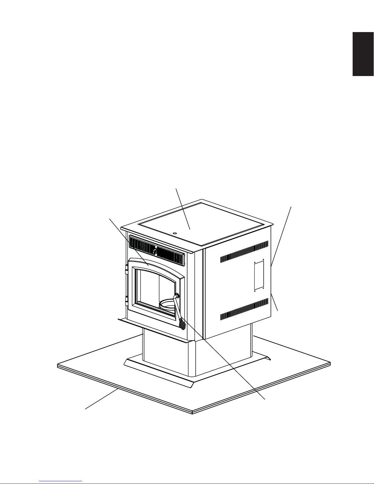
1.0 INSTALLATION OVERVIEW
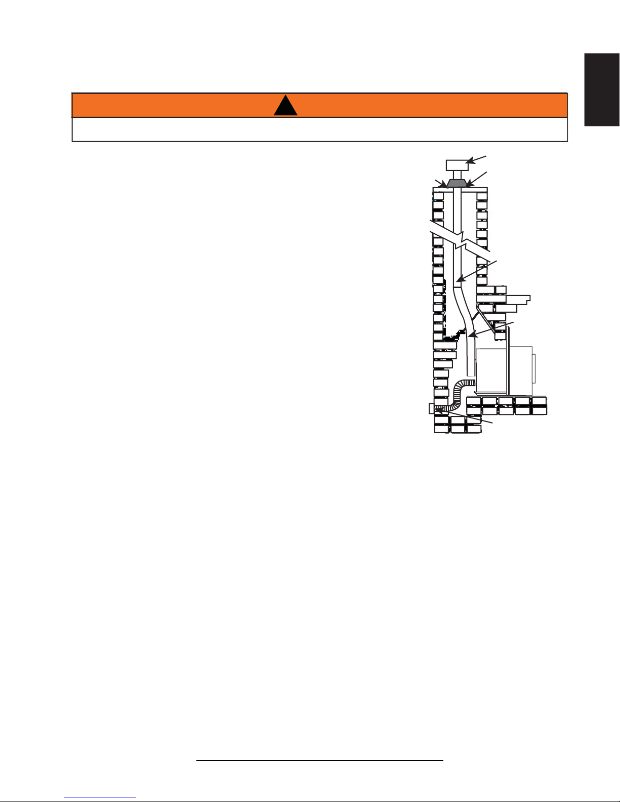
1.1 STOVE
Rating plate, see
“RATING PLATE
INFORMATION”
section.
Venting, see “GENERAL VENTING”
Door, see “FINISHING - INSTALLING
THE VIEWING DOOR” section.
and “INSTALLATION” sections.
3
EN
Floor, see “INSTALLATION PLANNING FLOOR PROTECTION REQUIREMENTS” section.
See “OUTSIDE AIR”
section.
Handle, see “DOOR
HANDLE INSTALLATION”
section.
W415-1477 / A / 10.19.16
Page 4
4
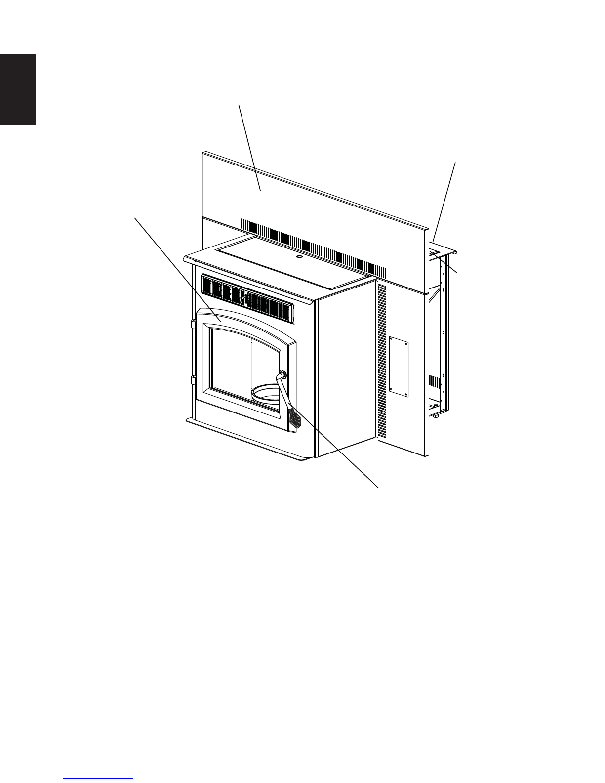
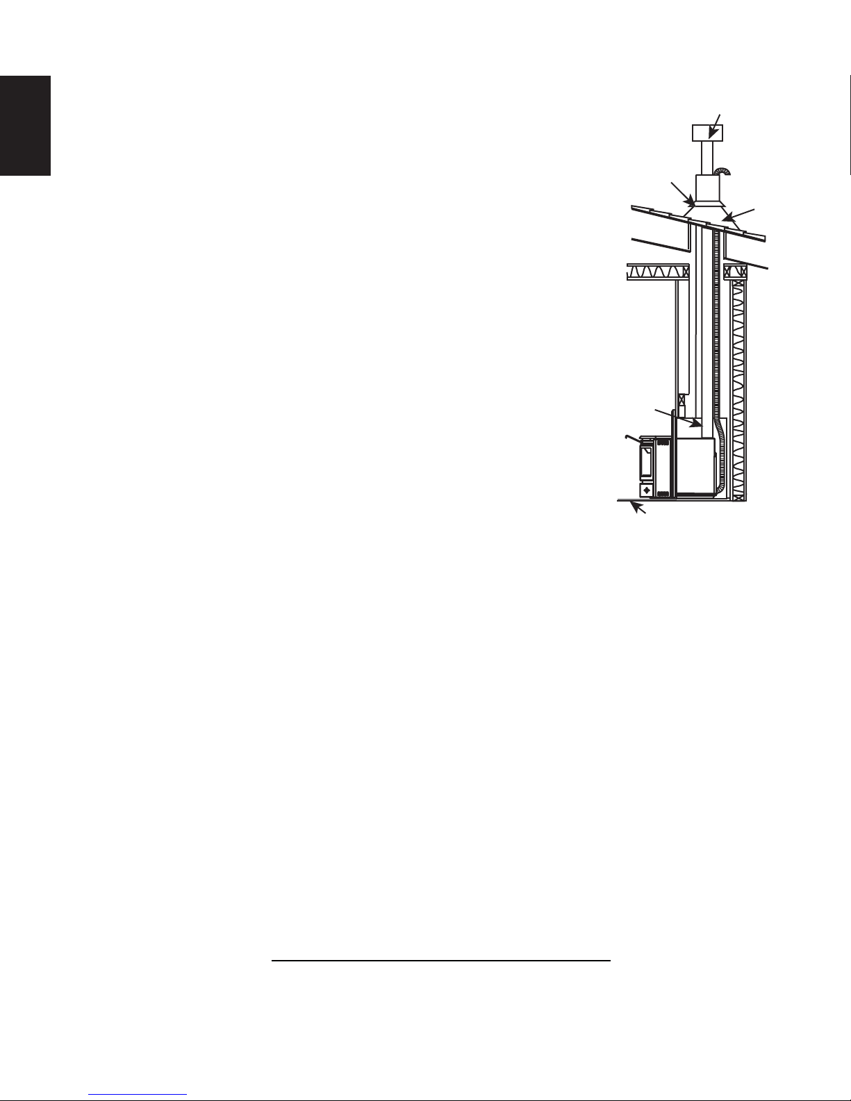
1.2 INSERT
EN
Flashing, see “FLASHING
INSTALLATION” section.
Venting, see “VENTING” and
“INSTALLATION” sections.
Door, see “FINISHING INST ALLING THE VIEWING DOOR” section.
Rating plate, see
“RATING PLATE
INFORMATION”
section.
W415-1477 / A / 10.19.16
Handle, see “DOOR
HANDLE INSTALLATION”
section.
Page 5
2.0 INTRODUCTION
5
!
WARNING
• THIS APPLIANCE IS HOT WHEN OPERATED AND CAN CAUSE SEVERE BURNS IF CONTACTED.
• Do not operate appliance before reading and understanding operating instructions. Failure to operate appliance according to
operating instructions could cause fi re or injury. Contact the local building or fi re authority and follow their guidelines. Notify
your insurance company of this appliance as well.
• Never try to repair or replace any part of the appliance unless instructions are given in this manual. All other work should be
done by a trained technician.
• Risk of burns. The appliance should be turned off and cooled before servicing.
• Do not operate without fully assembling all components.
• Do not install damaged, incomplete or substitute components.
• Risk of cuts and abrasions. Wear protective gloves and safety glasses during installation. Sheet metal edges may be sharp.
• Children and adults should be alerted to the hazards of high surface temperature and should stay away to avoid burns or
clothing ignition. Toddlers, young children and others may be susceptible to accidental contact burns. A physical barrier is
recommended if there are at risk individuals in the house. To restrict access to an appliance or stove, install an adjustable
safety gate to keep toddlers, young children and other at risk individuals out of the room and away from hot surfaces.
• Clothing or other fl ammable material should not be placed on or near the appliance.
• Due to high temperatures, the appliance should be located out of traffi c and away from furniture and draperies.
• Ensure you have incorporated adequate safety measure to protect infants/toddlers from touching hot surfaces.
• Even after the appliance is out, the glass and/or screen will remain hot for an extended period of time.
• Check with your local hearth specialty dealer for safety screens and hearth guards to protect children from hot surfaces.
These screens and guards must be fastened to the fl oor.
• Any safety screen or guard removed for servicing must be replaced prior to operating the appliance.
• It is imperative that the control compartments, burners and circulating blower and its passageway in the appliance and venting
system are kept clean. The appliance and its venting system should be inspected before use and at least annually by a
qualifi ed service person. More frequent cleaning may be required due to excessive lint from carpeting, bedding material, etc.
The appliance area must be kept clear and free from combustible materials, gasoline and other fl ammable vapors and liquids.
• Under no circumstances should this appliance be modifi ed.
• Do not use this appliance if any part has been under water. Immediately call a qualifi ed service technician to inspect the
appliance and to replace any part of the control system which has been under water.
• Do not operate the appliance with the glass door removed, cracked or broken. Replacement of the glass should be done by a
licensed or qualifi ed service person. The viewing door and ashpan must be closed and latched during operation.
• Do not strike or slam shut the appliance glass door.
• Only doors / optional fronts certifi ed with the unit are to be installed on the appliance.
• Keep the packaging material out of reach of children and dispose of the material in a safe manner. As with all plastic bags,
these are not toys and should be kept away from children and infants.
• If the appliance is not properly installed, a house fi re may result. Do not expose the appliance to the elements (ex. rain, etc.)
and keep the appliance dry at all times. Wet insulation will produce an odour when the appliance is used.
• The chimney must be sound and free of cracks. Clean your chimney a minimum of twice a year and as required.
• The heater is designed and approved for pelletized wood fuel only. Any other type of fuel burned in this heater will void the
warranty and safety listing. D
or paint thinners / solvents, plastic, materials containing asbestos, construction debris, railroad ties or treated wood, manure
or animal remains, salt water driftwood or salted materials, unseasoned wood, coloured paper, cardboard, plywood or
particleboard.
• Do not start a fi re with chemicals or fl uids such as gasoline, engine oil, etc.
• Ashes must be disposed in a metal container with a tight lid and placed on a non-combustible surface well away from the
home or structure.
• Your appliance requires periodic maintenance and cleaning. Failure to maintain your appliance may lead to smoke spillage in
your home.
• The exhaust system must be completely straight and properly installed. It is recommended that the pellet vent joints be sealed
with a minimum 500°F (260°C) silicone sealant. Install according to the vent manufacturer’s instructions.
• Ensure clearances to combustibles are maintained when building a mantel or shelves above the appliance. Elevated
temperatures on the wall or in the air above the appliance can cause melting, discolouration or damage to decorations, a T.V.
or other electronic components.
• During a power outage this appliance will not operate. If a power outage does occur, check the appliance for smoke spillage
and open a window if any smoke spills into the room.
• Keep foreign objects out of the hopper.
• Disconnect the power cord before performing any maintenance. NOTE: Turning the pellet feed to “OFF” does not
disconnect all power to the heater.
• Do not throw this manual away. This manual has important operating and maintenance instructions that you will need at a
later time. Always follow the instructions in this manual.
• At no point should you use fi rewood or fi relogs in this appliance. The use of which could cause a house fi re.
• This appliance must be connected to a standard 115 V, 50Hz grounded electrical outlet. Do not use an adapter plug or sever
the grounding prong. Do not route the electrical cord underneath, in front of, or over the appliance.
• When installed in a mobile home, the appliance must be bolted to the fl oor, have outside air, and NOT BE INSTALLED IN THE
BEDROOM (per H.U.D. requirements). Check with local building offi cials.
o not burn trash or garbage, lawn clippings / waste, rubber, waste petroleum products, paints
3.8C
EN
W415-1477 / A / 10.19.16
Page 6
EN
6
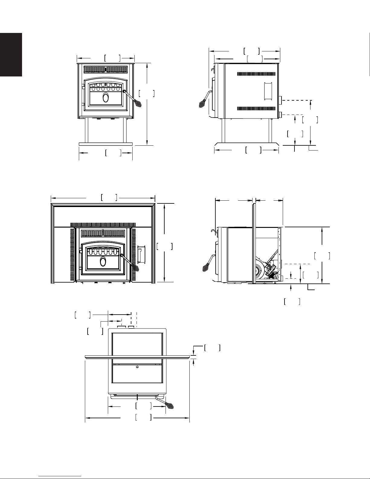
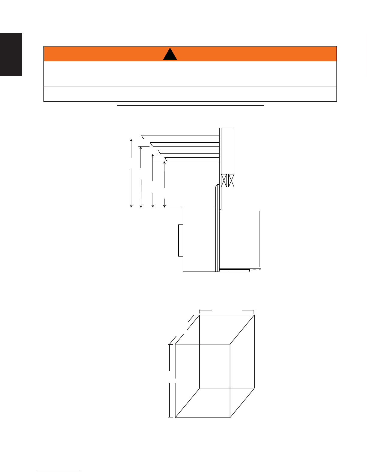
2.1 DIMENSIONS
2.1.1 STOVE
21 1/4"
540mm
30 5/16"
770mm
25 7/8"
24 1/4"
657mm
616mm
17"
432mm
11 5/8"
295mm
19 11/16"
500mm
2.1.2 INSERT (COMPLETE WITH FLASHING)
38 3/8"
975mm
29 3/8"
746mm
8 1/2"
220mm
CENTRE OF AIR INTAKE
5 5/8"
143mm
CENTRE OF EXHAUST
1 1/4"
32mm
23 1/2"
A
*
597mm
B
*
CENTRE OF
AIR INTAKE
7 1/8"
181mm
1 7/8"
47mm
CENTRE OF
AIR INTAKE
CENTRE OF
EXHAUST
20 13/16"
529mm
CENTRE OF
EXHAUST
21 1/4
38 3/8"
* A and B are adjustable, see "SPECIFICATIONS" section.
W415-1477 / A / 10.19.16
540mm
975mm
Page 7

2.2 SPECIFICATIONS
AB
Adjustable Flashing 11" (279mm) to
13" (330mm)
Electrical Rating 115 Volts, 3.6 Amps, 60Hz
Watts During Ignition Sequence 400 (approximately)
Watts During Operation 180 (approximately)
Weight Stove 158 lbs (1003kg) / Insert 140 lbs (889kg)
Exhaust Collar 3" (76mm)
Intake Collar 2" (51mm)
Hopper Capacity 45 Pounds (20kg)
Burn Rate 1.5 to 4.5 (Pounds Per Hour) / 0.7 to 2 (Kilograms Per Hour)
BTU/Hr 12750 to 38250
Approximate Maximum Heating Capacity (in square feet)* 800 to 2000 Sq. Feet / 74 to 186 Sq. Meters
Maximum Burn Time on Low Burn** 30 Hours
* Heating capacity will vary depending on the home's fl oor plan, degree of insulation, and the outside temperature. It is
also affected by the fuel size, quality, and moisture level.
** Small pellets will increase or decrease the stated burn rates and burn times. Differences of plus or minus 20%
depending on fuel quality may occur.
10 1/2" (267mm) to
12 1/2" (317mm)
7
EN
2.3 GENERAL INSTRUCTIONS
!
WARNING
ALL WIRING SHOULD BE DONE BY A QUALIFIED ELECTRICIAN AND SHALL BE IN COMPLIANCE
WITH LOCAL CODES. IN THE ABSENCE OF LOCAL CODES, USE THE CURRENT CSA C22.1
CANADIAN ELECTRIC CODE (IN CANADA) OR THE ANSI/NFPA NO. 70 NATIONAL ELECTRIC CODE
IN THE UNITED STATES.
DO NOT CONNECT THIS APPLIANCE TO A CHIMNEY FLUE SERVING ANOTHER APPLIANCE. DO
NOT CONNECT TO ANY AIR DISTRIBUTION DUCT OR SYSTEM.
PROVIDE ADEQUATE CLEARANCE FOR SERVICING AND OPERATING THE APPLIANCE.
PROVIDE ADEQUA TE VENTILA TION.
NEVER OBSTRUCT THE FRONT OPENING OF THE APPLIANCE.
OBJECTS PLACED IN FRONT OF THE APPLIANCE MUST BE KEPT A MINIMUM OF 48” (1219.2mm)
FROM THE FRONT FACE OF THE APPLIANCE.
W415-1477 / A / 10.19.16
Page 8

8
Thank you for purchasing a Wolf Steel Ltd. Pellet Appliance. This appliance is designed for use with Pelletized
Wood Only.
EN
Please read this entire manual before installation and use of this pellet fuel-burning room appliance. Failure to
follow these instructions could result in property damage, bodily injury or even death.
Keep this manual handy for future reference.
This Pellet Appliance, when installed, must be electrically grounded in accordance with the local codes, or in
the absence of local codes, use the current CSA C22.1 Canadian Electrical Code in Canada or the ANSI/NFPA
70 National Electrical Code in the United States.
This appliance will not operate using natural draft or without a power source for the blower systems and fuel
feed system.
These appliances are equipped with levelling screws that penetrate the front corners of the fi rebox. If these
screws are missing it will have a negative infl uence on the performance of this appliance. Ensure that the
levelling screws are tightened into position.
The protective wrap on plated parts is best removed when the assembly is at room temperature but this can be
improved if the assembly is warmed, using a hair dryer or similar heat source.
If the appliance is installed directly on carpeting, vinyl tile or other combustible material other than wood
fl ooring, the appliance shall be installed on a non-combustible hearth pad extending the full width and depth.
2.4 GENERAL INFORMATION
2.4.1 FUEL
4.5B
This appliance is designed to burn wood pellet fuel. In addition, a corn/wood pellet mixture with a maximum
50% corn can be burned. Burning any other fuel, that is not approved for use with this appliance, will void the
warranty.
Important: The corn/wood pellet mixture needs to be mixed evenly before being put into the hopper.
W415-1477 / A / 10.19.16
Page 9
2.4.2 PELLET SPECIFICATIONS
9
!
WARNING
IT IS IMPORTANT TO SELECT AND USE ONLY PELLETS THAT ARE DRY AND FREE OF DIRT
OR ANY IMPURITIES SUCH AS HIGH SALT CONTENT. DIRTY FUEL WILL ADVERSELY AFFECT
THE OPERATION AND PERFORMANCE OF THE APPLIANCE AND WILL VOID THE WARRANTY.
THE PELLET FUEL INSTITUTE (P.F.I.) HAS ESTABLISHED STANDARDS FOR WOOD PELLET
MANUFACTURERS. WE RECOMMEND THE USE OF PELLETS THAT MEET OR EXCEED THESE
STANDARDS. ASK YOUR DEALER FOR A RECOMMENDED PELLET TYPE.
Pellet quality is important, please read the following:
Your Wolf Steel Ltd. Pellet Appliance has been designed to burn premium hard or soft wood pellets only. Do
not use any other type of fuel such as fi re logs or fi re starting pellets, as this will void the warranties stated in
this manual.
The performance and heat output of the pellet appliance is directly related to the quality and moisture of the
pellets. Store pellets in a cool dry area to prevent moisture absorption.
P.F.I. PELLET STANDARDS:
Inorganic Fines (fi ne
particles)
Bulk Density 38 pound per cubic foot minimum
Size 1/4" (6.4mm) to 5/16" (8mm) diameter, 1/2" - 1 1/2" (13mm
Ash Content No more than 2%
Moisture Content 8% maximum
Chlorides 300 parts per million by weight
Trace Metals Less than 100mg/kg
Heat Content Approximately 8200 BTU/Hr per pound minimum
Construction Waste Not to contain any waste materials
1% maximum through a 1/8" (3.2mm) screen
- 38mm) long maximum
64.1
If the fuel does not comply to
this standard the appliance
may not operate as designed.
We recommend the use of
premium grade (1% ash
content) for longer appliance
life and less frequent cleaning.
EN
2.4.3 CORN SPECIFICATIONS
Use only clean-shelled corn with a moisture content less than 15% and approximate fuel value of 7,000 BTU/
lb (16,200 kJ/kg). Do not attempt to burn corn with higher moisture content or burn lesser grade fuels. Do not
burn other types of agricultural pellets or by-products (alfalfa, cherry pits, olive pits, nut shells, etc.) as they
are not permitted to be burned in this appliance.
Corn must be clean and free of debris. Never burn corn right from the fi eld. Damage caused by dirty corn is
not covered by the Lifetime Limited Warranty. Ask for screened corn only. Stalk parts, excessive fi nes and
cob remnants will clog the air fl ow holes in the burn plate. Check the corn for foreign objects.
Use only a maximum 50% corn to pellet mixture.
W415-1477 / A / 10.19.16
Page 10
10
U.S. Environmental Protection Agency:
Certifié conforme à la norme d’ émanation de particles de
2015.Non approuvé pour la vente après le 15 mai, 2020
: 40 CFR Part 60, Subpart AAA.
3.3 Grammes par heure.
to comply with 2015 particulate emissions standards.
0, Subpart AAA.
3.3 Grams Per Hour
CorneCo
CORNER 2”CORNE
M
RMIN 1.5 LB/HR
M
MAX 4.5 LB/HR
on
D.D.
DÉGAGEMENTS MINIMDÉGAGEMENT
CÔTÉ 6” CÔTÉ 6”
ARRIÈRE 3” ARRIÈRE 3”
oor
Protection
Protection de Ptti d
plancherplancher
3”
3”
”
CertifieCertif
40 CFR PartCFR Pa
820120192019
22334
66
8
HOT WHILE IN OPERATION. DO NOT TOUCH. KEE HOT WHILE IN OPERATION. DO NOT TOUCH. KE
RMÉES DURANT LE MÉE
SEULEMENT.
I
tInterior
Through Wall Ventsgh Wall Ven
Installations à Travers leInstallations à Travers
Protection deProtection de
Protection deProtection d
Protection d
plancherplancherpl
rplancher
plancher
CHAUFFAGE D’UNE MANIÈRE ALLANT À AUFFAGE D’UNE MANIÈR
2.4.4 SAFETY FEATURES
HIGH LIMIT SWITCH: Your appliance is equipped with a high limit switch. In the event that the temperature
EN
2.4.5 EPA COMPLIANCE
of the appliance approaches an unsafe operating temperature, this switch will shut down the pellet feed,
which will eventually shut down the unit. If this happens, it is important to fi nd out why the unit overheated.
Contact your local dealer.
LOW LIMIT SWITCH: This switch will automatically shut down the appliance if the fi re goes out or fails to
light within 15 minutes.
HOPPER DOOR INTERLOCK: Your appliance is equipped with a micro switch in the hopper assembly that
shuts-off the auger when the hopper door is opened. Closing the door switches the auger back on, allowing
pellets to feed again.
VACUUM SWITCH: This switch will sense lack of air fl ow through the appliance and shut down the pellet
feed. This lack of fl ow could be caused by a blocked vent.
POWER FAILURE: In the event of a power failure, the appliance will shut down. Once power is restored, the
appliance will re-start, unless the convection air temperature has gone above the high limit switch setting. If
this happens, contact your local dealer.
We suggest that our woodburning hearth products
be installed and serviced by professionals who are
certified in the U.S. by the National Fireplace
Institute® (NFI) as NFI Woodburning Specialists or
who are certified in Canada by
Wood Energy Technical
Training (WETT).
2.5 RATING PLATE INFORMATION
For rating plate location, see
“INSTALLATION OVERVIEW”
section.
This illustration is for reference
only. Refer to the rating plate
on the appliance for accurate
information.
NOTE: The rating plate must
remain with the appliance
at all times. It must not be
removed.
- INSTALL AND USE ONLY IN ACCORDANCE WITH THE
MANUFACTURER’S INSTRUCTIONS AND LOCAL
BUILDING CODES.
- MINIMUM CEILING HEIGHT: 7FT (2.13M) HEARTH
9700539 (WSL)
4001657 (NGZ)
4001658 (NAC)
4001659 (WUSA)
- KEEP VIEWING AND ASH REMOVAL DOORS TIGHTLY CLOSED DURING OPERATION.
- CONTACT LOCAL BUILDING AND FIRE OFFICIALS ABOUT RESTRICTIONS AND
INSTALLATION INSPECTION IN YOUR LOCAL AREA.
- SUITABLE FOR USE IN MOBILE HOMES WHEN USED WITH OUTSIDE AIR
INSTALLATION KIT.
- REFER TO INSTALLATION INSTRUCTIONS OR LOCAL BUILDING CODES WHEN
PASSING EXHAUST SYSTEM THROUGH COMBUSTIBLE WALL OR CEILING.
- FUEL: FOR USE WITH PELLET FUEL ONLY.
THIS WOOD APPLIANCE NEEDS PERIODIC INSPECTION AND REPAIR FOR PROPER OPERATION.
CONSULT THE OWNER’S MANUAL FOR FURTHER INFORMATION. IT IS AGAINST UNITED STATE
FEDERAL REGULATIONS TO OPERATE THIS WOOD APPLIANCE IN A MANNER INCONSISTENT
WITH THE OPERATING INSTRUCTIONS IN THE OWNER’S MANUAL.
- INSTALLER ET UTILISER CONFORMÉMENT AUX INSTRUCTIONS DU FABRICANT ET AUX CODES
DU BÂTIMENT LOCAUX.
- HAUTEUR DE PLAFOND MINIMALE 7 PI. (2,13 m)
BASE DE PROTECTION/PROTECTION DE PLANCHER COMBUSTIBLE : SI INSTALLÉ SUR UN
PLANCHER COMBUSTIBLE, L’APPAREIL DOIT ÊTRE PLACÉ SUR UNE PLAQUE PROTECTRICE
INCOMBUSTIBLE S’ÉTENDANT SUR 6” À L’AVANT.
- NE PAS RACCORDER CET APPAREIL À LA CHEMINÉE D’UN AUTRE APPAREIL.
- REMPLACER LA VITRE PAR UNE VITRE EN CÉRAMIQUE SEULEMENT.
DANGER : RISQUE DE SECOUSSE ÉLECTRIQUE. DÉBRANCHER L’ALIMENTATION ÉLECTRIQUE
AVANT DE PROCÉDER À L’ENTRETIEN.
- GARDER LA PORTE VITRÉE ET LA PORTE DU TIROIR À CENDRES BIEN FERMÉES DURANT LE
FONCTIONNEMENT.
- CONTACTER LES AUTORITÉS LOCALES DU BÂTIMENT ET DU SERVICE DES INCENDIES AU
SUJET DES RESTRICTIONS ET DES INSPECTIONS D’INSTALLATION DANS VOTRE RÉGION.
- PEUT ÊTRE INSTALLÉ DANS UNE MAISON MOBILE SI INSTALLÉ CONJOINTEMENT AVEC UNE
PRISE D’AIR EXTÉRIEUR.
- SE RÉFÉRER AUX INSTRUCTIONS D’INSTALLATION OU AUX CODES DU BÂTIMENT LOCAUX
LORSQUE LE SYSTÈME D’ÉVACUATION TRAVERSE UN MUR OU UN PLAFOND COMBUSTIBLES.
- COMBUSTIBLE : POUR USAGE AVEC DES GRANULES SEULEMENT.
CET APPAREIL AU BOIS DOIT FAIRE L’OBJECT D’UNE INSPECTION ET D’UN ENTRETIEN
PÉRIODIQUES POUR UN FONCTIONNEMENT ADÉQUAT. CONSULTEZ LE MANUEL
D’INSTRUCTIONS POUR PLUS D’INFORMATION. LES RÈGLEMENTS FÉDÉRAUX DE L’ÉTATS-UNIS
INTERDISENT D’UTILISER CET APPAREIL DE CHAUFFAGE D’UNE MANIÈRE ALLANT À
L’ENCONTRE DES INSTRUCTIONS DE FONCTIONNEMENT CONTENUES DANS CE MANUEL.
YEAR:
MONTH:
WOLF STEEL LTD.
24 NAPOLEON ROAD, BARRIE, ON, L4M 0G8 CANADA
MODEL TPS35 LISTED PELLET FUEL BURNING ROOM HEATER TESTED TO: ASTM E 1509, ULC/ORD C1482-M90, ULC S627
EXTENSION / COMBUSTIBLE FLOOR PROTECTION:
IF INSTALLED ON A COMBUSTIBLE FLOOR, UNIT MUST
BE PLACED ON A NON-COMBUSTIBLE FLOOR PROTECTOR
EXTENDING 6” IN FRONT.
- DO NOT CONNECT THIS UNIT TO A CHIMNEY FLUE
SERVING ANOTHER APPLIANCE.
- REPLACE GLASS WITH ONLY CERAMIC GLASS.
DANGER: RISK OF ELECTRICAL SHOCK. DISCONNECT
POWER BEFORE SERVICING UNIT.
MANUFACTURE DATE: / DATE DE FABRICATION:
2016
243658710912111
2017 2018
2017201
2019 2020
Straight Installation Corner Installation
3”
Floor
6”
Protection
Through Wall Installation
MINIMUM CLEARANCES TO COMBUSTIBLE
SIDE 6” CORNER 2”
U.S. ENVIROMENTAL PROTECTION AGENCY Certified to comply with July 1992 Particulate Emission Standards
HOT WHILE IN OPERATION. DO NOT TOUCH. KEEP CHILDREN,CLOTHING AND FURNITURE AWAY.
3”
Protection de
Protection de
anche
plancher
plancher
Installations à Travers le Mur
DÉGAGEMENTS MINIMAUX AUX MATÉRIAUX COMBUSTIBLES
CÔTÉ 6” COIN 2”
ARRIÈRE 3” PLAFOND 48”
ATTENTION :
LES ENFANTS, LES VÊTEMENTS ET LES MEUBLES À L’ÉCART. LE CONTACT PEUT CAUSER
DES BRÛLEURS DE PEAU.
U.S. Environmental Protection Agency:
2015.Non approuvé pour la vente après le 15 mai, 2020
3.3 Grammes par heure.
3”
2”
Tee
6”
Floor
Fl
Protection
Interior Vertical Vent
nterior Vertical Ven
3”
2”
2
Protection de
plancher
Évents Verticaux Intérieurst
L'APPAREIL EST CHAUD LORSQU’IL FONCTIONNE. NE PAS TOUCHER. TENIR
Through Wall Vents Interior Vertical Vent
ELECTRICAL RATING
MIN 1.5 LB/HR
IN 1.5 LB/H
MAX 4.5 LB/HR
AX 4.5 LB/HR
40 CFR Part 60, Subpart AAA.
6”
6”
TPS35
120V 3.6A 60HZ
Certified to comply with 2015 particulate emissions standards.
3.3 Grams Per Hour
Installation en Coin
Installation de coin
2”
45°
Coude
45°
2”
6”
6”
Protection de
plancher
Évents à Travers le Mur
IDÉBIT D’ALIMENTATION
MIN. 1.5 LB/H
MAX. 4.5 LB/H
Certifié conforme à la norme d’ émanation de particles de
CARACTÉRISTIQUES ÉLECTRIQUES
120 V 60 Hz
: 40 CFR Part 60, Subpart AAA.
2”
6”
Té
2”
6”
Protection de
plancher
Évents Verticaux Intérieurs
W385-2035 / A
6”
Floor Protection
6”
Tee
2”
2”
W415-1477 / A / 10.19.16
Page 11

3.0 INSTALLATION PLANNING
11
!
WARNING
READ ENTIRE MANUAL BEFORE YOU INSTALL OR USE THIS APPLIANCE. FAILURE TO FOLLOW THE
INSTRUCTIONS MAY RESULT IN PROPERTY DAMAGE, BODILY INJURY OR EVEN DEATH.
USE ONLY WOLF STEEL APPROVED OPTIONAL ACCESSORIES AND REPLACEMENT PARTS WITH
THIS APPLIANCE. USING NON-LISTED ACCESSORIES AND REPLACEMENT PARTS (BLOWERS,
DOORS, LOUVRES, TRIMS, GAS COMPONENTS, VENT COMPONENTS, ETC.) COULD RESULT IN A
SAFETY HAZARD AND WILL VOID THE LIMITED LIFETIME WARRANTY.
Check with local building offi cials for any permits required for installation of this pellet appliance and notify your
insurance company before proceeding with installation.
Before installing we recommend placing the appliance outside and load 5 lbs (2.3k) of pellets inside the hopper. Plug the appliance in and let it run on HIGH until the pellets run out. This will cure the paint and burn off
most of the oils on the steel, thereby minimizing any smell inside the home.
68.1A
3.1 INSTALLATION OPTIONS
Stove model:
To install in a Residential or Mobile Home see "MOBILE HOME INSTALLATION" section. For alcove
installations see "ALCOVE INSTALLATION REQUIREMENTS" section. For horizontal vent or vertical vent see
"VENTING" section. Outside air, see "OUTSIDE AIR" section.
Insert model:
To install as an insert into an existing masonry appliance or factory built appliance see "VENTING" section. To
install into a combustible enclosure, see "INSTALLATION INTO A COMBUSTIBLE ENCLOSURE" section.
EN
3.2 APPLIANCE PLACEMENT
Have an authorized dealer install the appliance. If you install the appliance yourself, have your dealer review
your installation plans and/or installation.
Draw out a detailed plan of the installation including dimensions and verify the dimensions with the
requirements listed in this manual.
You may wish to adjust the appliance position slightly to ensure the vent does not intersect with a framing
member. Appliance must be positioned so that no combustibles are within, or can swing within (e.g. drapes,
doors), 4 feet (1.2m) of the front of the appliance.
67.1B
3.3 LEVELLING THE APPLIANCE
Move the appliance close to its fi nal position. This appliance is equipped with levelling screws located on the
base. Level using the levelling screws. Levelling the appliance will eliminate rocking or excessive noise when
the fan is in operation. Once the appliance is level, move it partially into place to allow for all connections to be
made. It is not practical to level the appliance once it has been installed. Determine the required depth prior to
installing the appliance and adjust the levelling screws accordingly.
67.2
W415-1477 / A / 10.19.16
Page 12
12
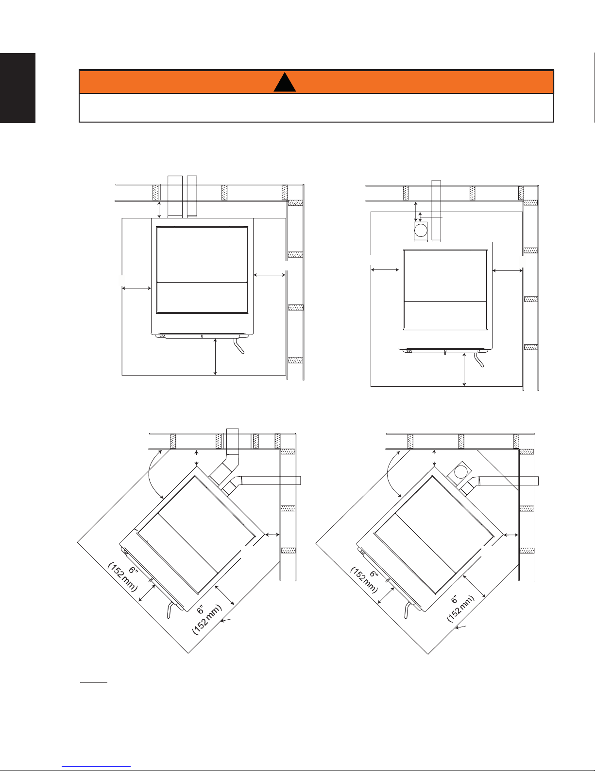
3.4 MINIMUM CLEARANCE TO COMBUSTIBLES
EN
DO NOT INSTALL INTO ANY AREA HAVING LESS THAN 48" (1219mm) (CEILING TO APPLIANCE
BOTTOM, EXCLUDING HEARTH HEIGHT).
3.4.1 STRAIGHT INSTALLATION
Through the Wall Installations complete
with outside air
3”(76mm)
6”
(152mm)
Floor
Protection
6”
(152mm)
!
6”
(152mm)
WARNING
3”(76mm)
(152mm)
Interior Vertical Vents
2” (51mm)
6”
Floor
Protection
6”
(152mm)
6”
(152mm)
3.4.2 CORNER INSTALLATION
Through the Wall Vents complete with outside air Interior Vertical Vents
2” (51mm)
45°
NOTE: If interior vertical pellet vent is used, the clearance to the back wall is determined by the
upward-turning elbow or "Tee". It will vary in depth depending on the brand of pellet vent used [it is
approximately 5" (127mm)]. Before placing the appliance, connect the elbow or "Tee" and allow for the
minimum 3" (76mm) clearance to the combustible wall.
45°
Elbow
2”
(51mm)
Floor Protection
45°
2” (51mm)
2”
(51mm)
Floor Protection
W415-1477 / A / 10.19.16
Page 13

3.5 FLOOR PROTECTION REQUIREMENTS INSTALLATION
13
The appliance must be installed on a non-combustible fl oor protector extending the full depth of the
appliance and extending a minimum 6" (152mm) in front and on either side (minimum .018" thick - 26 gauge)
of the fuel loading and ash removal openings.
The fl oor protector must extend under and 2" (51mm) beyond each side and back of a "Tee" (if used).
NOTE: Floor protection is required for spark and ash shielding, but not for limiting fl oor temperatures
from the radiant heat of the appliance. The appliance was designed and safety tested so that without
any protection, the fl oor would not overheat.
Refer to local building codes for suitable fl oor protection materials.
3.6 OUTSIDE AIR
Available from your Authorized Dealer (114KT)
Outside air must not be drawn from an enclosed space (garage, unventilated crawl space).
NOTE: Wolf Steel Ltd. strongly suggests using outside air for all residential installations, especially for
those that are energy effi cient, air-tight homes.
Outside air supply must not be over 15' (4.6m) long.
Outside air vents must be made with 1 3/4" (45mm) diameter or larger metal or aluminum duct with a metal
screen attached to the end to keep out rodents (P.V.C. or other materials may not be used).
The outside air inlet must not be above or within 12" (305mm) of the chimney termination, must have a rain
cap or down-turned elbow to prevent the water from entering and be located so that it will not become
plugged by snow or other material.
EN
Outside air is required for all combustible built-in enclosure installations.
3.7 MOBILE HOME
THE STRUCTURAL INTEGRITY OF THE MANUFACTURED HOME FLOOR, WALL, AND CEILING ROOF
Installation into a manufactured home or mobile home should be installed in
accordance with the Manufactured Home Construction and Safety Standard,
Title 24 CFR, Part 3280, in the United States or the Mobile Home Standard,
CAN/CSA Z240 MH Series, in Canada.
The appliance must be grounded to the steel chassis of the mobile home
(Some states do not require this; check with your local building department).
!
WARNING
DO NOT INSTALL IN A SLEEPING ROOM.
MUST BE MAINTAINED.
STOVE
ILLUSTRATED
29.4A
W415-1477 / A / 10.19.16
Page 14
14
4.0 VENTING
EN
4.1 TYPE OF VENT
Must be an approved 3" (76.2mm) or 4" (102mm) diameter Type "L" or "PL" vent, vented to the outside or
connect the vent to a factory built type "A" chimney using an adaptor; and/or stainless steel chimney liner for
masonry appliance installations. Use 4" (102mm) diameter vent if vent or liner height is over 15' (4.6m) or if
installation is over 4,000' (1219m) above sea level.
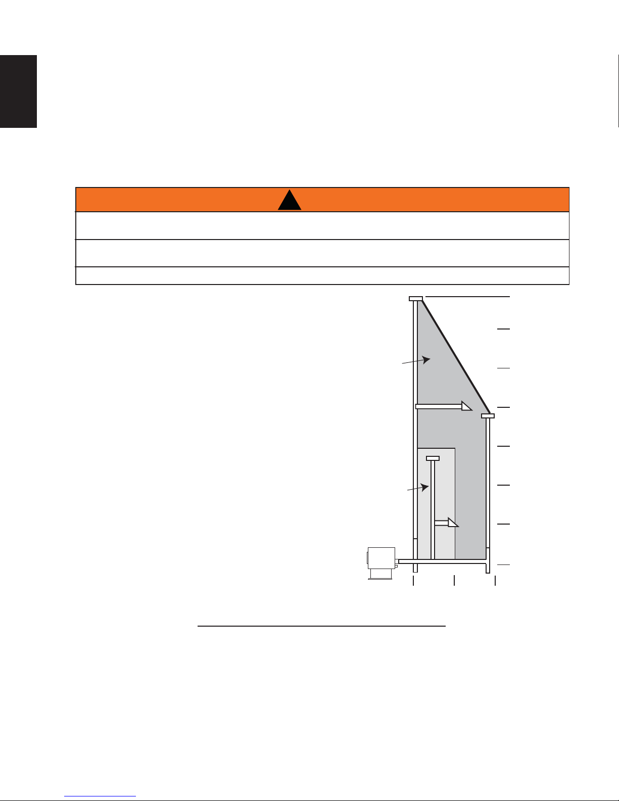
4.2 PELLET VENT INSTALLATION
PELLET VENT MUST MAINT AIN A MINIMUM 3" (76.2mm) CLEARANCE TO ANY COMBUSTIBLE (INSTALL
VENT AT CLEARANCES SPECIFIED BY THE VENT MANUFACTURER, CHIMNEY LINER EXCLUDED).
DO NOT CONNECT THE PELLET VENT TO A VENT OR CHIMNEY SERVING ANY OTHER APPLIANCE OR
DO NOT INST ALL A FLUE DAMPER IN THE EXHAUST VENTING SYSTEM OF THIS UNIT.
The vent must have a support bracket every 5’ (1.5m)when on
the exterior wall. To achieve optimum performance, keep vent
runs as short as possible, especially on horizontal installations.
MAXIMUM VENTING: Maximum venting height is 33’ (10.1m)
Maximum horizontal without vertical rise is 5’ (1.5m) straight
off the back of the appliance. Use no more than 180° of
elbows (two 90° elbows, or two 45° elbows and one 90°
elbow, etc), excluding the tee and the termination.
VENT INST ALLATION: Termination must exhaust above
the air inlet elevation, and parallel or above the exhaust
output of the pellet appliance. It is recommended that at
least 3’ (0.9m) of vertical pipe be installed to create some
natural draft. This is to help prevent the possibility of smoke
or odour entering the home during the appliance shut down
or in the event of a power outage. Horizontal sections must
have a 1/4” (6.4mm) rise every 12” (304.8mm) of travel if
longer than 3’ (0.9m).
The pellet vent connections must be sealed with HI-Temp
RTV Silicone and screwed together with at least 3 3/8”
(85.7mm) long stainless steel screws. Seal each vent
section by injecting a liberal amount of 500°F (260°C) RTV
silicone sealant into the gap. We recommend sealing the
outside of the vent connections to permit easier access
when servicing.
!
WARNING
HEATER.
diameter “L”
vent if venting
in this shaded
Use 3” (76.2mm)
or 4” (101.6mm)
diameter “L”
vent if venting
in this shaded
Use 4”
(101.6mm)
region.
region.
33’ (10.1m)
30’ (9.1m)
25’ (7.6m)
20’ (6.1m)
15’ (4.6m)
10’ (3.1m)
5’ (1.5m)
0
0
5’
(1.5m)
10’
(3.1m)
4.3 VENTING THE PELLET APPLIANCE
Use an approved wall thimble when passing the vent through walls and a ceiling support / fi restop spacer
when passing the vent through ceilings (maintain a 3" (76mm) clearance to any combustibles).
W415-1477 / A / 10.19.16
7.5D
Page 15
4.4 PELLET VENT TERMINATION
15
The vent termination must have an approved cap (to prevent water from entering) or a 45° downturn.
If the termination is located on a windy side of the house, a shield is recommended to prevent soot from
building up on the side of the house.
Horizontal terminations must protrude 12" (305mm) from the wall, vertical terminations require a minimum 24"
(610mm) above the highest point that it penetrates through the roof.
Depending on pellet quality, vent confi guration and air settings, black soot may occur on the terminal wall.
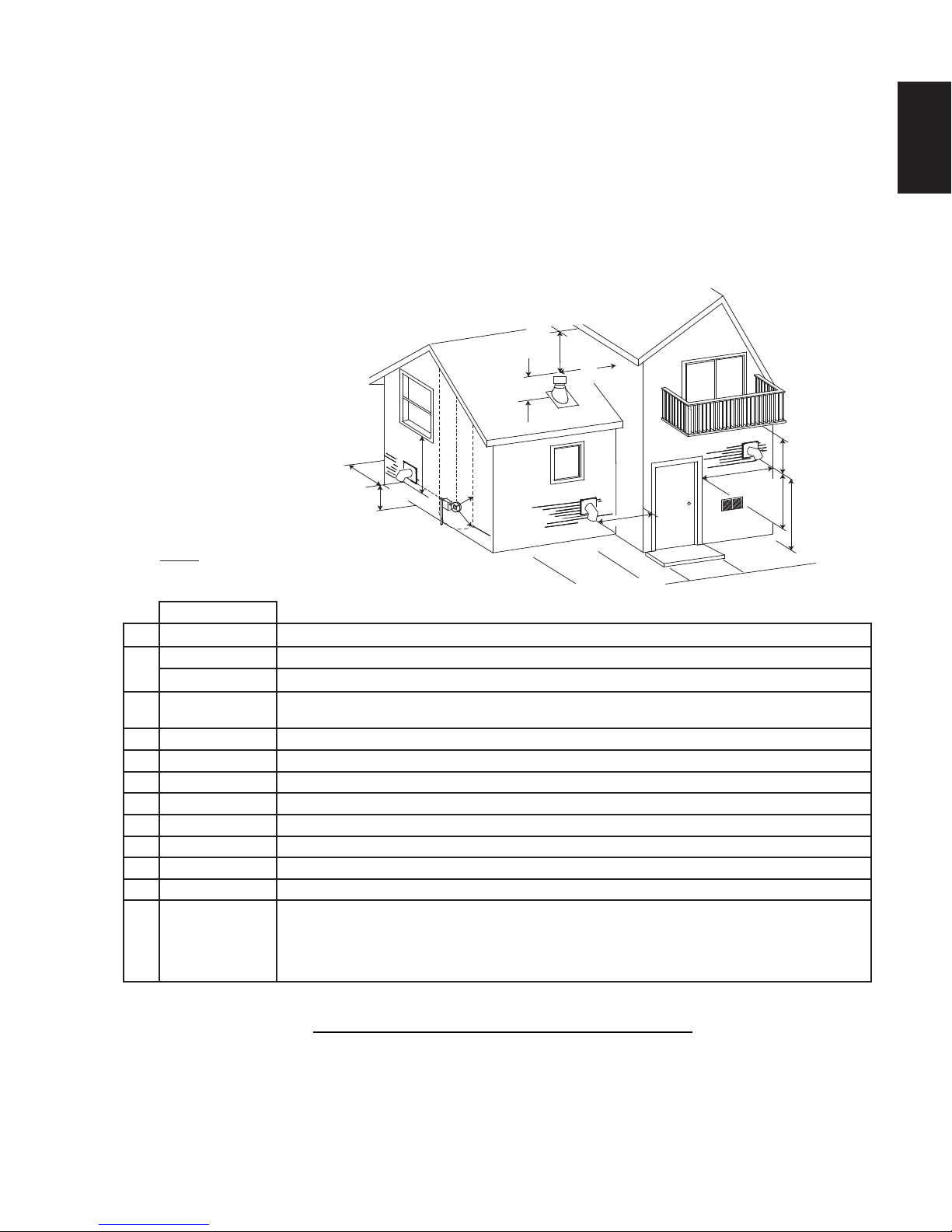
4.5 VENT TERMINAL CLEARANCES
D
A
NOTE: Illustration dimensions are to the center of
the exhaust exit point of the vent.
EN
E
C
K
J
G
I
F
H
B
B
L
E
CLEARANCES
A 12” (30.5cm) Clearance above grade, veranda porch, deck or balcony. (Including vegetation and mulch)
B
C
D 0” (0mm) Clearance to an outside corner wall.
E 3” (75mm) Clearance to an inside combustible corner wall or protruding combustible obstructions (vent chase, etc.)
F 9” (22.9cm) Clearance to a non-mechanical air supply inlet to the building or a combustion air inlet to any other appliance.
G 3’ (0.9m) Clearance to a mechanical air supply inlet.
H 7’ (2.1m) ** Clearance above a paved sidewalk or paved driveway located on public property.
J 24” (61cm) Clearance above the roof.
K 2’ (0.6m) Clearance from an adjacent wall including neighbouring buildings.
L
** This is a recommended distance. For additional requirements check local codes.
9” (22.9cm)* Clearance beside or below any windows or doors that open.
12” (30.5cm)* Clearance above any window or door that opens.
18”
(45.7cm)
I 12” (30.5cm)** Clearance under a veranda, porch, deck or balcony.
3’ (0.9m) within a
height of 15 feet
(13.7m) above the
meter / regulator
assembly
* Recommended to prevent condensation on windows and thermal breakage
Vertical clearance to ventilated soffi t located above the terminal within a horizontal distance of 2 feet
(0.6m) from the center line of the terminal.
Clearance to each side of center line extended above natural gas or propane meter / regulator assembly or
mechanical vent.
12.7C
W415-1477 / A / 10.19.16
Page 16
16
4.6 STOVE VENTING INSTALLATION EXAMPLES
EN
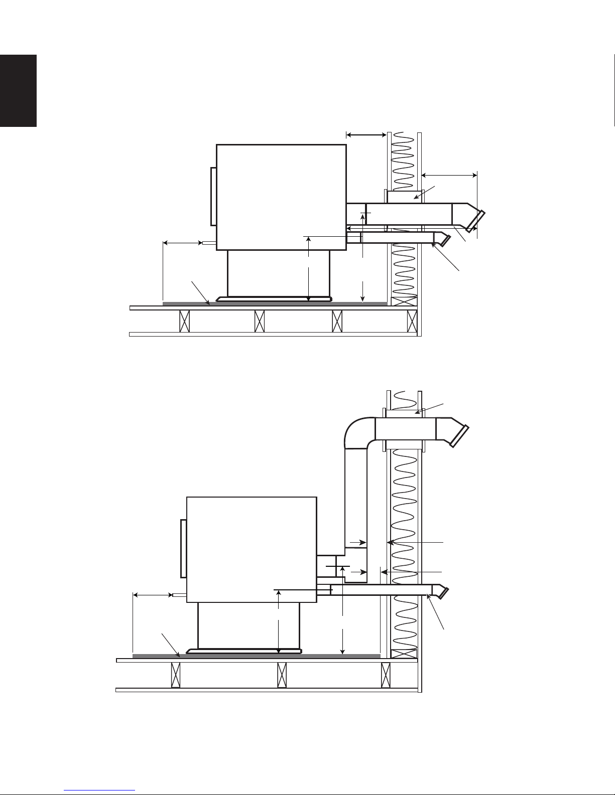
4.6.1 HORIZONTAL TERMINATION (THROUGH WALL)
6”(152mm)
Minimum
Floor
Protection
11 5/8”(295mm)
3”(76mm)
Minimum
17”
(432mm)
12”(305mm)
Minimum
Wall
Thimble
5’(1.5m)
Maximum
Outside Air
(Recommended)
4.6.2 VERTICAL RISE HORIZONTAL TERMINATION (THROUGH WALL)
6”(152mm)
Minimum
Floor
Protection
11 5/8”(295mm)
17”(432mm)
(Recommended)
Wall Thimble
3”(76mm)
2”(51mm)
Outside Air
W415-1477 / A / 10.19.16
Page 17
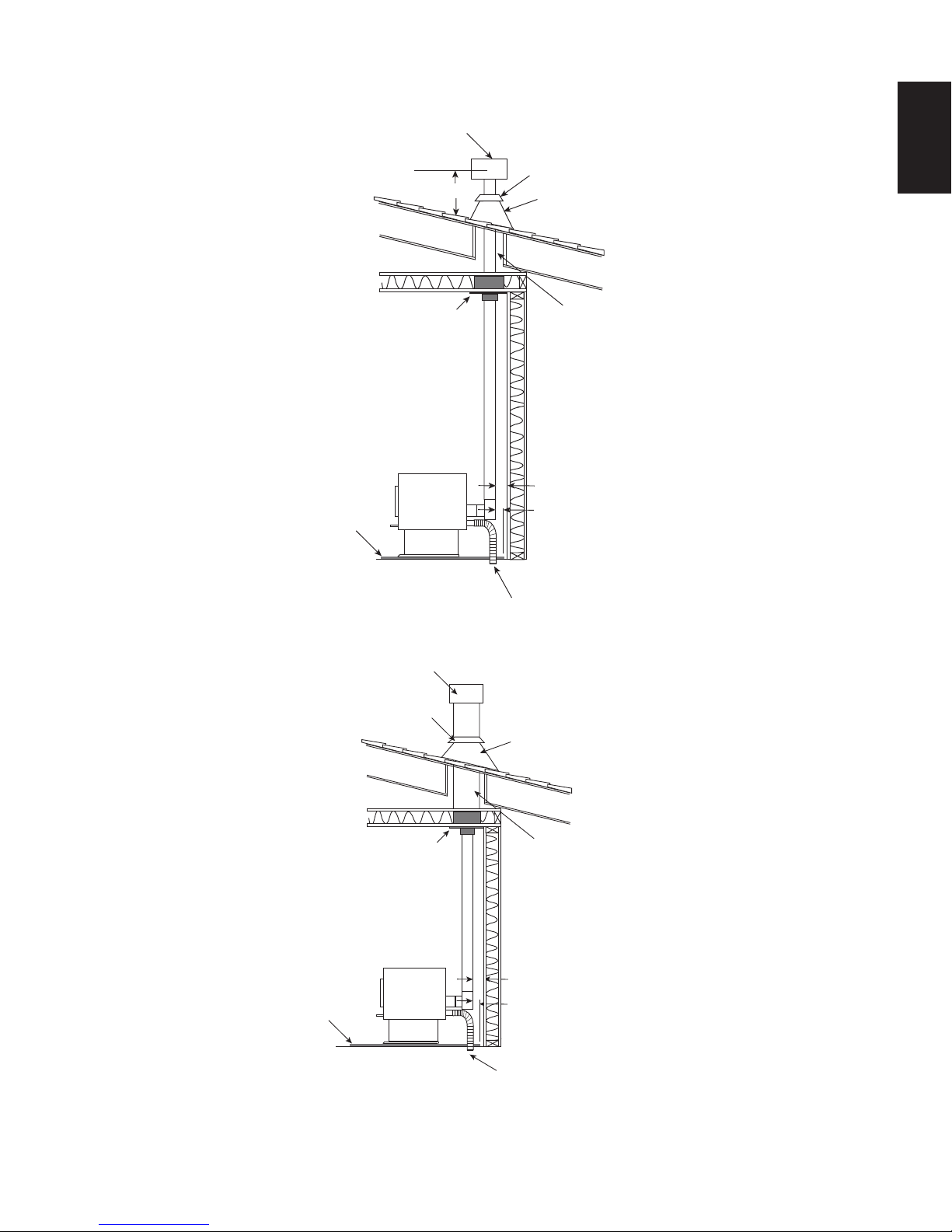
4.6.3 VERTICAL TERMINATION
17
Floor Protection
Vertical Cap
24”(610mm)
Ceiling Support
EN
Storm Collar
Roof Flashing
Vent must maintain
3”(76mm) clearance to
combustibles.
3”(76mm)
2”(51mm)
Outside air (Recommended)
(Installation showing inlet of out-
side air in ventilated crawl space)
4.6.4 CLASS A CHIMNEY RETROFIT
Vertical Cap
Storm Collar
Class A Chimney
Ceiling Support
Floor Protection
Roof Flashing
Vent must maintain
3”(76mm) clearance to
combustibles.
3”(76mm)
2”(51mm)
Outside air
(Recommended)
(Installation showing inlet of outside
air in ventilated
crawl space)
W415-1477 / A / 10.19.16
Page 18
EN
on
S
18
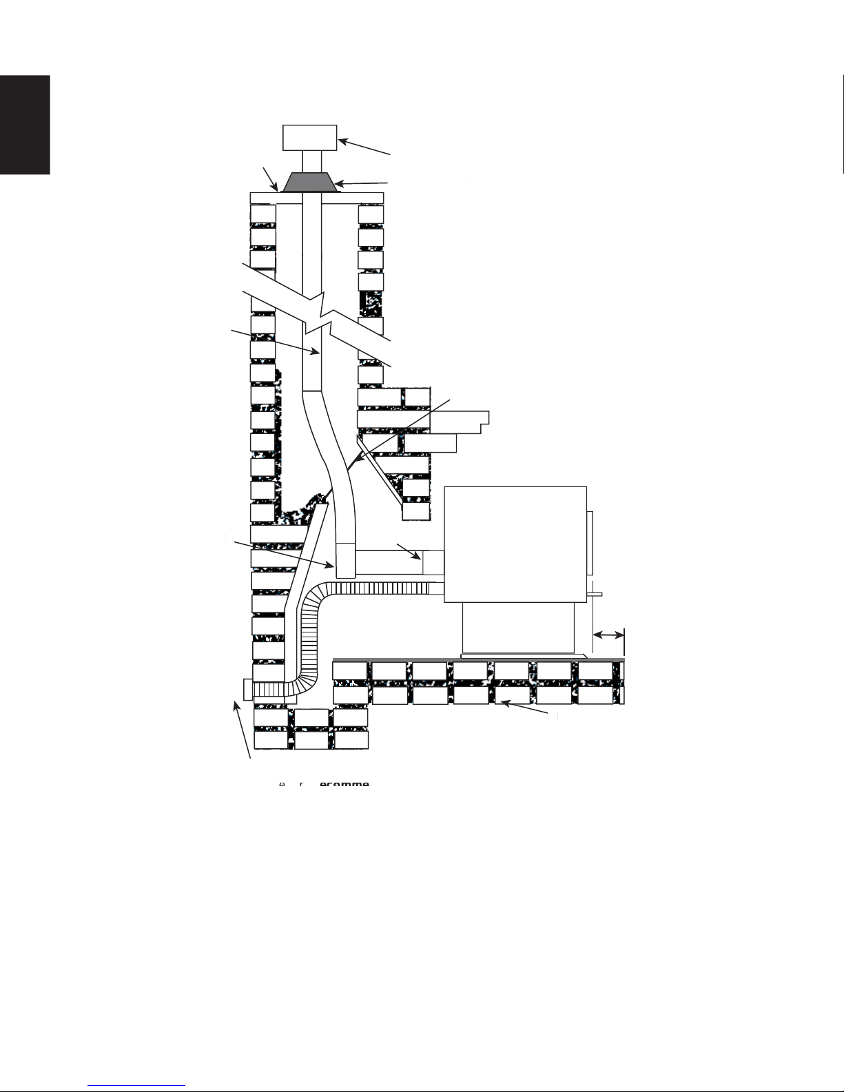
4.6.5 HEARTH MOUNT INSTALLATION
Chimney Cap
Pellet
Liner
Clean-out
ut
tee
Vertical Cap
Pellet
Vent
Storm Collar
torm Collar
Flue Cover
Bring outside air to the stove
Outside Air (Recommended)
For installation instructions See "TYPICAL EXISTING MASONRY" section.
6”(152mm)
MIN
Floor Protection
Floor Protecti
W415-1477 / A / 10.19.16
Page 19
4.7 INSERT VENTING INSTALLATION EXAMPLES
l
e
r
o
Cap
Ver
19
4.7.1 TYPICAL EXISTING MASONRY INSTALLATION
!
WARNING
DO NOT REMOVE BRICKS OR MORTAR FROM THE FIREPLACE.
Prior to installation:
When installing the insert into a masonry fi replace, do not
remove any bricks or masonry. Do not weaken the structure,
or reduce the protection for combustible materials to less then
that required by the National Building Code. Bolted or screwed
together pieces (smoke shelf / defl ectors) may be removed,
but must be able to be re-installed if the appliance is removed.
External trim pieces, which do not affect the operation of the
fi replace, may be removed provided they are available to be reinstalled in event the appliance is removed.
A warning label must be attached to the back wall of the fi replace
stating that “This fi replace has been altered to accommodate a
fi replace insert and must be re-inspected by a qualifi ed person
prior to re-use as a fi replace”.
Non-combustible fl oor protection must cover the fl ooring
underneath, as well as extend a minimum of 6” (152.4mm) in
front and to both sides of the appliance.
Cover Plate
Vertical Cap
Storm Collar
rm Colla
t
Pellet
Liner
Cover
Flue
EN
Clean all ashes out of the inside of the fi replace. Make sure
that the chimney and fi replace are free of cracks, loose mortar,
creosote deposits, blockage or other signs of deterioration.
If necessary, have any repair work done by a qualifi ed
professional before installing the appliance.
A. Remove the fi replace damper or fasten it permanently open.
B. Measure the throat of the fi replace and mark this shape on a piece of 24 (0.511mm) gauge sheet meta
(fl ue cover). Cut a hole sized for the pellet liner to lie directly below the fi replace fl ue opening. Allow 2”
(50.8mm) of material for a fl ange on all sides and cut to these measurements. Bend down the fl anges.
If you have never done this before, it might be a good idea to make a cardboard pattern and test it fi rst.
Fasten this fl ue cover in position as high as possible with two masonry screws per side through the
fl anges into the fi replace.
C. If you plan on connecting outside air it is recommended to do so at this time.
D. Install fl oor protection if necessary.
E. Connect the pellet vent with a clean out tee to the back of the insert. Refer to manufacturer’s
installation instructions to see “REAR TO TOP VENT CONVERSION INSTRUCTIONS” section and th
“GENERAL VENTING” section.
F. Run a liner down the chimney and connect to tee.
Outside Air
(Recommended)
G. Position the insert in it’s fi nal location.
H. Pull the excess length of liner out through the top of the chimney. Trim the excess liner, install the cap
and cap the chimney.
62.3B
W415-1477 / A / 10.19.16
Page 20
20
l
e
4.7.2 FACTORY BUILT FIREPLACE
EN
Prior to installation:
Do not weaken the structure or reduce the protection for
combustible materials to less then that required by the National
Building Code. Bolted or screwed together pieces (smoke shelf /
defl ectors) may be removed, but must be able to be re-installed
if the appliance is removed.
External trim pieces, which do not affect the operation of the
fi replace, may be removed provided they are available to be reinstalled in event the appliance is removed.
A warning label must be attached to the back wall of the
fi replace stating that “This heater has been altered to
accommodate a fi replace insert and must be re-inspected by a
qualifi ed person prior to re-use as a factory built fi replace”.
Non-combustible fl oor protection must cover the fl ooring
underneath, as well as extend a minimum of 6” (152.4mm) in
front and to both sides of the appliance.
Clean all ashes out of the inside of the fi replace. Make sure
that the chimney and fi replace are free of cracks, loose mortar,
creosote deposits, blockage or other signs of deterioration.
Storm
Collar
The smoke
shelf, damper
and baffles may
be removed
Vertical
Cap
Roof
Flashing
If necessary, have any repair work done by a qualifi ed
professional before installing the appliance.
A. Remove the fi replace damper or fasten it permanently
open.
B. Measure the throat of the fi replace and mark this shape on a piece of 24 (0.511mm) gauge sheet meta
(fl ue cover). Cut a hole sized for the pellet liner to lie directly below the fi replace fl ue opening. Allow 2”
(50.8mm) of material for a fl ange on all sides and cut to these measurements. Bend down the fl anges.
If you have never done this before, it might be a good idea to make a cardboard pattern and test it fi rst.
Fasten this fl ue cover in position as high as possible with two masonry screws per side through the
fl anges into the appliance.
C. If you plan on connecting outside air it is recommended to do so at this time.
D. Install fl oor protection if necessary.
E. Connect the pellet vent with a clean out tee to the back of the insert. Refer to manufacturer’s
installation instructions to see “REAR TO TOP VENT CONVERSION INSTRUCTIONS” section and th
“GENERAL VENTING” section.
F. Run a liner down the chimney and connect to tee.
G. Position the insert in it’s fi nal location.
Do not remove any part that would
alter the integrity in any way.
Floor Protection
H. Pull the excess length of liner out through the top of the chimney. Trim the excess liner, install the cap
and cap the chimney.
W415-1477 / A / 10.19.16
80.1A
Page 21

5.0 FRAMING (INSERT ONLY)
21
!
WARNING
RISK OF FIRE!
IN ORDER TO AVOID THE POSSIBILITY OF EXPOSED INSULATION OR VAPOUR BARRIER COMING
IN CONTACT WITH THE APPLIANCE BODY, IT IS RECOMMENDED THAT THE WALLS OF THE
APPLIANCE ENCLOSURE BE “FINISHED” (IE: DRYWALL / SHEETROCK), AS YOU WOULD FINISH
ANY OTHER OUTSIDE WALL OF A HOME. THIS WILL ENSURE THAT CLEARANCE TO
DO NOT NOTCH THE FRAMING AROUND THE APPLIANCE STAND-OFFS. FAILURE TO MAINTAIN
AIR SPACE CLEARANCE MAY CAUSE OVER HEATING AND FIRE. PREVENT CONTACT WITH
SAGGING OR LOOSE INSULATION OR FRAMING AND OTHER COMBUSTIBLE MATERIALS. BLOCK
OPENING INTO THE CHASE TO PREVENT ENTRY OF BLOWN-IN INSULATION. MAKE SURE
WHEN CONSTRUCTING THE ENCLOSURE ALLOW FOR FINISHING MATERIAL THICKNESS TO
MAINTAIN CLEARANCES. FRAMING OR FINISHING MATERIAL CLOSER THAN THE MINIMUMS
LISTED MUST BE CONSTRUCTED ENTIRELY OF NON-COMBUSTIBLE MATERIALS. MATERIALS
CONSISTING ENTIRELY OF STEEL, IRON, BRICK, TILE, CONCRETE, SLATE, GLASS OR PLASTERS,
OR ANY COMBINATION THEREOF ARE SUITABLE. MATERIALS THAT ARE REPORTED AS PASSING
ASTM E 136, STANDARD TEST METHOD FOR BEHAVIOUR OF MATERIALS IN A VERTICAL TUBE
FURNACE AT 1382°F (750°C) AND UL763 SHALL BE CONSIDERED NON-COMBUSTIBLE
MINIMUM CLEARANCE TO COMBUSTIBLES MUST BE MAINTAINED OR A SERIOUS FIRE HAZARD
THE APPLIANCE REQUIRES A MINIMUM ENCLOSURE HEIGHT. MEASURE FROM THE APPLIANCE
IF STEEL STUD FRAMING KITS WITH CEMENT BOARD ARE PROVIDED, OR SPECIFIED IN THE
IF SPECIFIED IN THE INSTALLATION INSTRUCTION FINISHING MUST BE DONE USING A NON-
COMBUSTIBLE MATERIAL SUCH AS NON-COMBUSTIBLE BOARD, CERAMIC TILE, MARBLE, ETC.
DO NOT USE WOOD OR DRYWALL. ANY FIRE RATED DRYWALL IS NOT ACCEPTABLE
COMBUSTIBLES IS MAINTAINED WITHIN THE CAVITY.
INSULATION AND OTHER MATERIALS ARE SECURED.
MATERIALS.
COULD RESULT.
BASE.
INSTALLATION INSTRUCTIONS, THEY MUST BE INSTALLED.
71.1C
EN
W415-1477 / A / 10.19.16
Page 22
22
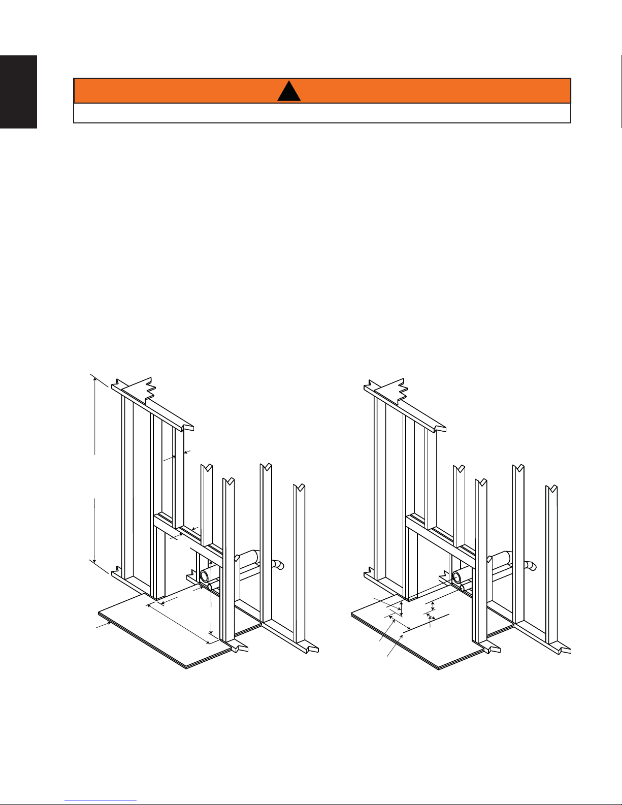
5.1 INSTALLATION INTO A COMBUSTIBLE ENCLOSURE
EN
!
WARNING
OUTSIDE AIR IS MANDATORY FOR A COMBUSTIBLE BUILT-IN ENCLOSURE INSTALL.
When installing the insert as a "built-in" appliance, it is important to maintain the clearances to combustibles,
see "MINIMUM CLEARANCE TO COMBUSTIBLES" section.
A non-combustible hearth must cover the fl ooring underneath, as well as, a minimum of six inches in front
and to both sides of the appliance.
A. Install fl oor protection.
B. Frame structure maintaining minimum clearances. Locate and frame openings for both the exhaust
and outside air. Outside air is mandatory for enclosure installations. See "OUTSIDE AIR" section.
C. Refer to vent manufacturer's installation instructions and to "GENERAL VENTING" section. Connect
the vent. Install fl ashing, see "FLASHING INSTALLATION" section.
D. Consideration must be taken during installation that removal of the insert is necessary for inspection
and annual maintenance. Install the vent cap.
3 1/2” (89mm)
MAX
40” (1016 mm)
MINIMUM
ENCLOSURE
HEIGHT
3 1/2”
(89mm)
MAX
17”
(432mm)
Non
combustible
floor protection.
This protection must
offer an R value of 0.4 (two
layers of 1/2” (13mm) thick cement board, total 1” (25mm) with each
layer rated with an R value of 0.2).
For temperature requirements, the enclosure space around and
33”
(838mm)
27”
(686mm)
7 1/8” (181mm)
4 7/8”
(124mm)
Centerline of
heater opening
1 7/8”
(48mm)
2” (51mm)
W415-1477 / A / 10.19.16
Page 23
5.2 MINIMUM ENCLOSURE CLEARANCES
(162mm)
40”
(1016mm)
MIN.
27”
(686mm)
MIN.
23
EN
6 3/8”
MIN.
2”
(51mm)
MIN.
3” (76mm) all around (Refer to
vent manufacturer’s instructions)
6”
(152mm)
Non-combustible
floor protection
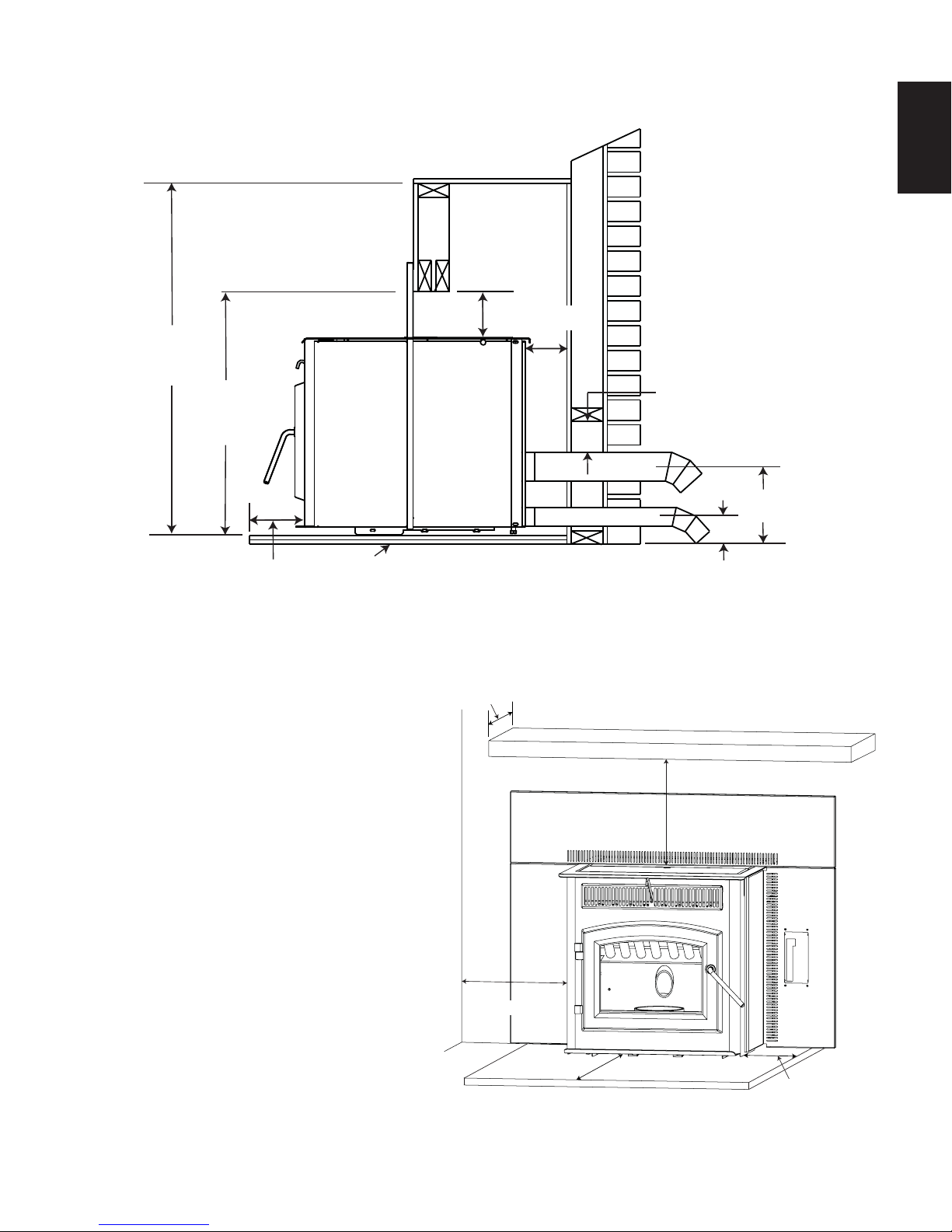
5.3 MINIMUM CLEARANCE TO COMBUSTIBLES
Side wall to appliance 8" (203mm)
Mantel to top of appliance 8" (203mm)
Top facing to appliance 6 3/8" (162mm)
Side facing to appliance 6" (152mm)
Floor protection* 6"* (152mm)
Mantel Depth / Length 10 (254mm)
* Floor Protection: Minimum 6" (152mm) in
front of door and to either side.
10”
(254mm)
Side Wall
10” (254mm)
8”(203mm)
7 1/8” (181mm)
1 7/8”
(48mm)
Mantel
MIN
8” (203mm)
MIN
6” (152mm)
6” (152mm)
W415-1477 / A / 10.19.16
Page 24
24
5.4 INSERT MINIMUM MANTEL CLEARANCES
EN
!
WARNING
RISK OF FIRE, MAINTAIN ALL SPECIFIED AIR SPACE CLEARANCES TO COMBUSTIBLES. FAILURE
TO COMPLY WITH THESE INSTRUCTIONS MAY CAUSE A FIRE OR CAUSE THE APPLIANCE TO
OVERHEAT. ENSURE ALL CLEARANCES (I.E. BACK, SIDE, TOP, VENT, MANTEL, FRONT, ETC.) ARE
CLEARLY MAINTAINED.
WHEN USING PAINT OR LACQUER TO FINISH THE MANTEL, THE PAINT OR LACQUER MUST BE
HEAT RESISTANT TO PREVENT DISCOLOURATION.
73.1
16” (406mm)MANTEL
14” (356mm)
12” (305mm)
10”
(254mm)
10” (254mm)
8”
(203mm)
14”
(356mm)
12”
(305mm)
5.5 MINIMUM STOVE ALCOVE INSTALLATION REQUIREMENTS
W415-1477 / A / 10.19.16
35”(889mm)
30”
(762mm)
48”
(1219mm)
STOVE
Minimum Alcove Dimensions
Page 25
6.0 FINISHING
25
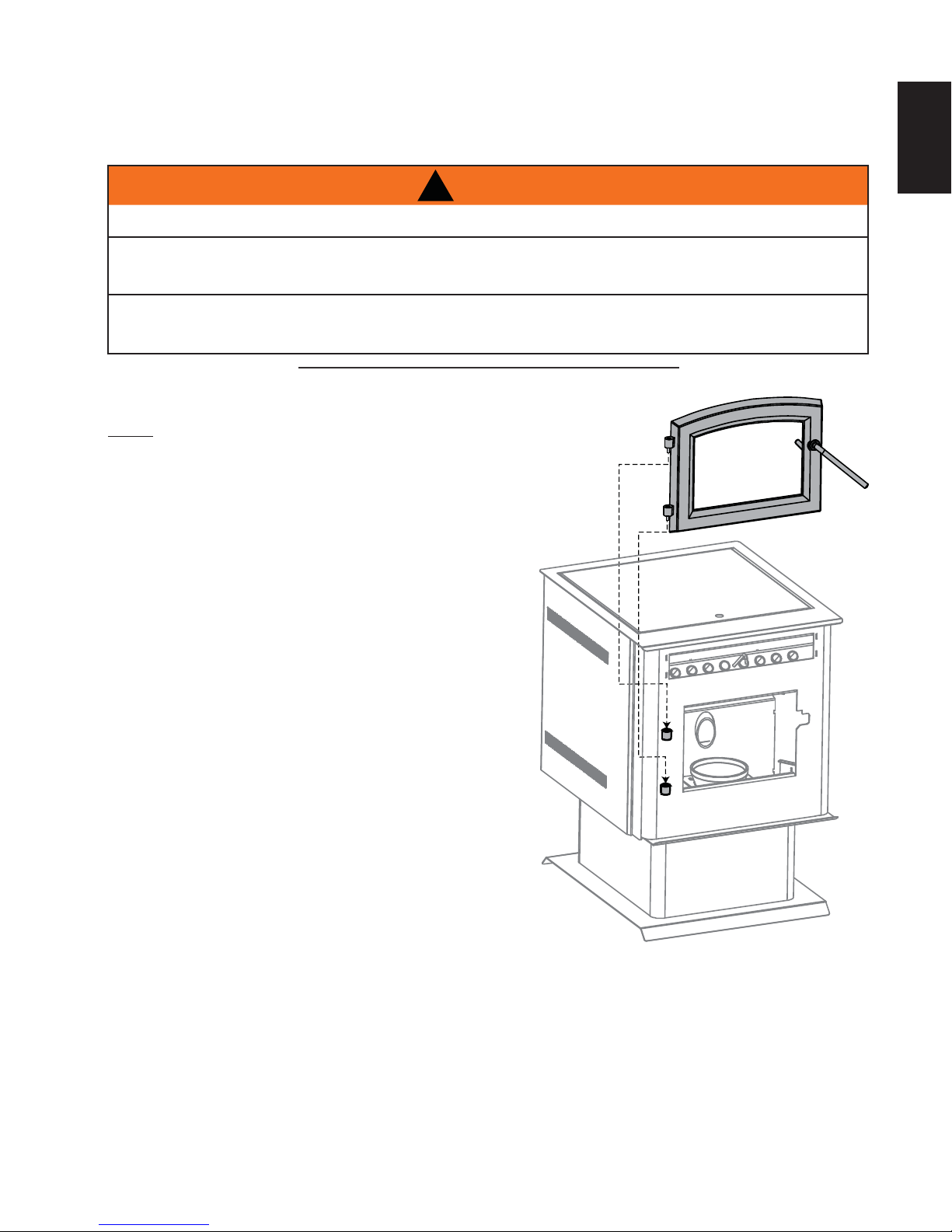
6.1 VIEWING DOOR INSTALLATION
!
WARNING
GLASS MAY BE HOT, DO NOT TOUCH GLASS UNTIL COOLED.
THE DOOR LATCHES ARE PART OF A SAFETY SYSTEM AND MUST BE PROPERLY ENGAGED. DO
NOT OPERATE THE APPLIANCE WITH LATCHES DISENGAGED.
BEFORE DOOR IS REMOVED TURN THE APPLIANCE OFF AND WAIT UNTIL APPLIANCE IS COOL TO
THE TOUCH. DOORS ARE HEAVY AND FRAGILE SO HANDLE WITH CARE.
75.2
The main viewing door has been boxed separate from the appliance, but
MUST be installed before burning the appliance.
A. Align the pins on the door to the bushing on the left side of the
appliance. Lower into place until both bushings touch.
EN
W415-1477 / A / 10.19.16
Page 26

EN
26
6.2 DOOR HANDLE INSTALLATION
NOTE: DOOR MAY NOT BE AS
ILLUSTRATED
FRONT VIEW
DOOR
SPRING
WASHER
DOOR HANDLE
LATCH
LOCK
NUT
DOOR
HANDLE
6.3 DECORATIVE INSET
SPACER
NOTE: Position of
door handle latch.
98.1
W415-1477 / A / 10.19.16
Page 27
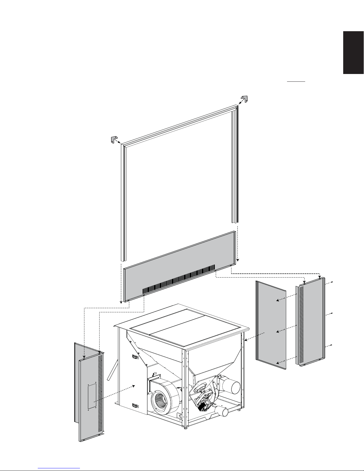
6.4 FLASHING INSTALLATION
A. Secure the left fl ashing to the left side with the three screws provided. Repeat for the right side.
B. Side panels are attached to the fi rebox by the three magnets per side.
C. Lower the top panel, aligning the slots in the top panel with the holes in the side panel.
D. Secure the top panel by to the side panels with the screws and washers provided. NOTE: Make sure
the side panels are tight to the fi rebox before securing the screws.
E. The fl ashing can be adjusted forward and
backward by re-adjusting the
fl ashing along the
27
EN
magnets.
F. Slide trim over
fl ashing.
TRIM
TOP
PANEL
RIGHT
SIDE
RIGHT
FLASHING
LEFT
SIDE
LEFT
FLASHING
W415-1477 / A / 10.19.16
Page 28
EN
28
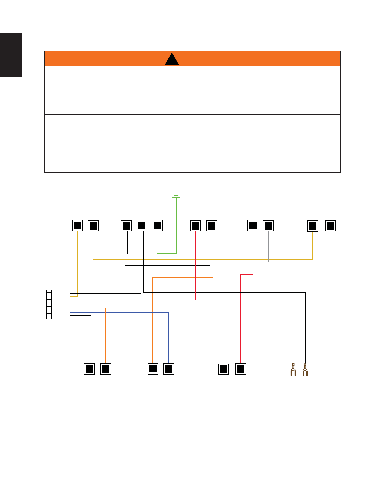
7.0 WIRING DIAGRAM
DO NOT USE THIS APPLIANCE IF ANY PART HAS BEEN UNDER WATER. CALL A QUALIFIED
SERVICE TECHNICIAN IMMEDIATELY TO HAVE THE APPLIANCE INSPECTED FOR DAMAGE TO THE
RISK OF ELECTRICAL SHOCK OR EXPLOSION. DO NOT WIRE 110V TO THE VALVE OR TO THE
APPLIANCE WALL SWITCH. INCORRECT WIRING WILL DAMAGE CONTROLS.
ALL WIRING SHOULD BE DONE BY A QUALIFIED ELECTRICIAN AND SHALL BE IN COMPLIANCE
WITH LOCAL CODES. IN THE ABSENCE OF LOCAL CODES, USE THE CURRENT CSA22.1 CANADIAN
ELECTRIC CODE IN CANADA OR THE CURRENT NATIONAL ELECTRIC CODE ANSI/NFPA NO. 70 IN
ALWAYS LIGHT THE PILOT WHETHER FOR THE FIRST TIME OR IF THE GAS SUPPLY HAS RUN OUT,
WITH THE GLASS DOOR OPENED OR REMOVED.
!
WARNING
ELECTRICAL CIRCUIT.
THE UNITED STATES.
69.2_2
HIGH
LIMIT
YELLOW
YELLOW
WHITE
WHITE
CONVECTION
BLOWER
ORANGE
WHITE
POWER
CORD
BLACK
BLACK
WHITE
COMBUSTION
BLOWER
RED
ORANGE
GREEN
BLUE
IGNITOR
RED
WHITE
ORANGE
RED
HOPPER
SWITCH
RED
AUGER
MOTOR
RED
GREY
PURPLE
LOW LIMIT
VACUUM
SWITCH
YELLOW
BLACK
GREY
W415-1477 / A / 10.19.16
Page 29
8.0 OPERATING INSTRUCTIONS
29
8.1 PROPER PELLET LOADING
Before loading pellets into the hopper fi rst transfer the pellets from it’s original plastic bag to a metal bucket.
Keep in mind that the auger stops when the lid is opened. If the lid is opened for several minutes, the fi re may
extinguish.
NOTE: If the pellets are kept in the plastic bag, the bag may come in contact with the appliance causing
the bag to melt and the pellets to spill.
DO NOT load pellets into the hopper if they have been exposed to moisture. Moisture can cause pellets
to swell and cause blockage in the feed system. Thoroughly dry pellets before placing into hopper.
47.10
8.2 PRE-START CHECK
Before installing this appliance we recommend a “PRE-BURN” inspection to help burn off the odours that are
associated with the fi rst burn. If possible, move the appliance outside and add approximately 5 lbs (2.3kg) of
pellets into the hopper. Plug the power cord into a typical wall receptacle.
The appliance is equipped with a control board that has been shipped in manual mode.
When fi rst starting a new pellet appliance, or when you completely empty the hopper of pellets you can press
and hold the prime button to get the pellets into the burn pot quicker.
Slide the "ON/OFF" button to "ON":
This starts the ignition cycle.
The auger comes on and runs for approximately 3 minutes.
EN
The igniter comes on and will stay on until proof of fi re determined by the appliance temperature.
At anytime during the ignition cycle, once proof of fi re is met, the appliance goes into normal
operating mode.
NOTE: Flame should appear in the burn pot within 3 to 7 minutes from commencing the ignition cycle.
The ignition cycle should end in approximately 12 to 15 minutes. At this point adjustments to feed rate
can be made or the appliance will revert to the previous setting. If proof of fi re is not established in 15
minutes, the appliance will shut down and will need to be turned back on again. If the appliance shuts
down, empty the pellets from the burn pot into an empty non-combustible container and restart. Never
empty pellets from burn pot back into hopper.
8.3 MANUAL APPLIANCE LIGHTING
APPLIANCE MAY BE HOT.
OTHER THAN PLACING A HANDFUL OF PELLETS IN THE BURN POT FOR LIGHTING MANUALLY,
NEVER FEED PELLETS THROUGH THE GLASS VIEWING DOOR. AN "OVERFIRE" CONDITION
COULD OCCUR, IF MORE PELLETS ENTER THE FIREBOX THAN WHAT THE FEED TUBE CAN
DELIVER. PELLETS MUST ONLY BE BURNED WITHIN THE BURN POT.
NEVER USE GASOLINE TYPE LANTERN FUEL, KEROSENE, CHARCOAL LIGHTER FLUID, OR
SIMILAR LIQUIDS TO START OR ‘FRESHEN UP’ A FIRE IN THIS APPLIANCE. KEEP ALL SUCH
LIQUIDS WELL AWAY FROM THE APPLIANCE WHILE IT IS IN USE.
Your appliance can be lit manually without using the automatic igniter by following the procedure below.
!
WARNING
• Press the ON / OFF button.
• Place a “handful” of pellets into the burn pot.
• Cover with a small amount of approved (non-volatile) fi re starter gel.
• Light fi re starter with a match and close the viewing door.
47.11
W415-1477 / A / 10.19.16
Page 30

30
8.4 LIGHTING INSTRUCTIONS
After fi lling the hopper with pellets, switch the control to manual so that you have full control of the appliance
EN
until you have familiarized yourself with its functions.
Do not try to operate your appliance with the viewing door or hopper lid open. Safety switches will disable the
pellet feed auger.
A. Press the "ON/OFF" button "ON" to initiate the ignition cycle.
B. Once the ignition cycle has ended (approximately 12 to 15 minutes) adjustments can be made to the
control.
8.5 REMOTE CONTROL
INDICATOR LIGHTS
Solid
- Indicates set feed rates.
Flashing
- Indicates an operation failure.
HEAT ADJUSTMENT
Increases or decreases the heat
level.
PRIME
Speed feeding of pellets into the burn
pot.
OPERATING MODE
Sets the appliances operating
mode.
ON / OFF
Used to turn the appliance on or
off.
W385-0500
AUTO / MANUAL
This switch is used to select the operating mode.
MANUAL: Sliding the switch down to manual will allow you to manually select the heat level. In
manual mode the appliance will run at your desired settings indefi nitely, until you manually turn the
appliance off or the appliance runs out of pellets.
AUTO: Slide the switch to the top position (AUTO). The auto mode operates using either a wall or a
remote control thermostat. If the thermostat does not call for heat in a 60 minute period the appliance
will turn off completely. When the thermostat does call for heat, it will initiate an ignition cycle.
ON / OFF
Use this button to turn the appliance on and off.
HEAT LEVEL
Pressing the heat level button will increase the heat level one setting. Pressing the heat level button down will
decrease the heat level one setting. The red lights at the top left of the control will indicate the heat setting 1
through 3.
PRIME
Pressing and holding this button will turn the auger continuously which increases the feed of pellets into the
burn pot. This is convenient when using the appliance for the fi rst time or when you have completely emptied
the hopper and need to restart the appliance.
W415-1477 / A / 10.19.16
Page 31

8.6 CONTROL ADJUSTMENT
FEED TRIM
Both the combustion fan speed and the feed rate have been factory set but may need to be adjusted
(trimmed) on site. Due to the variables (i.e. vent size, length and pellet quality), the factory settings may not be
ideal for every installation. To help keep the fl ame from extinguishing on the minimum heat level, the feed rate
can be trimmed when in normal operation (after the 15 minute ignition cycle).
31
EN
HEAT
LEVEL
PRIME
HEAT
LEVEL
PRIME
HEAT
LEVEL
PRIME
FACTORY SET MORE FUEL LESS FUEL
Pushing the "PRIME" button when in the lowest heat setting will indicate the current trim.
To slightly increase the amount of fuel being fed into the burn pot, hold the prime button down while you
toggle the heat level button so that the top light goes out.
To slightly decrease the amount of fuel being fed into the burn pot, hold the prime button down while you
toggle the heat level button so that the bottom light goes out.
BLOWER TRIM
Similar to the feed rate, it may be necessary to trim the speed of the
combustion blower. Due to specifi c installations, it may be necessary
to increase or decrease the amount of air moving through the burn pot
to achieve maximum effi ciency. In order to adjust the blower trim you
need access to the back of the control panel. Start by either removing
the side panel (pedestal) or behind the fl ashing (insert), using a small
screw driver turn the screw to adjust the blower (clockwise to increase/
counter-clockwise to decrease) and reinstall the panel / fl ashing that
was removed.
NOTE: The blower voltage is factory set for 92.5 V, it must not be
turned lower than 90 V. Every 180° degree turn of the trim screw
will increase or decrease the voltage by 0.2 V. Increasing the blower
speed beyond 95 V is not recommended as this will increase the
pellet consumption, reduce the heat output and may also damage
some of the components.
BLOWER
TRIM
SCREW
TERMINALS
W415-1477 / A / 10.19.16
Page 32

32
8.7 THERMOSTAT INSTALLATION
EN
An optional millivolt thermostat is available to help keep the room temperature constant.
NOTE: The thermostat must be installed by a qualifi ed installer.
• Disconnect the power supply.
• Remove the right side panel to gain access to the rear of the control panel.
• Strip and connect the two thermostat wires to the two screw terminals on the back of the control
panel.
NOTE: The control must be in AUTO to control the appliance with a thermostat.
8.8 SHUTDOWN INSTRUCTIONS
Slide the "ON/OFF" button to "OFF". Your appliance will cycle down and the blower will remain operating until
your appliance has cooled.
9.0 NORMAL OPERATING SOUNDS
EXHAUST BLOWER
The flow of exhaust gases may
create a low-pitched hum. As
the pellet feed rate is altered
this sound will change.
CONVECTION BLOWER
A low hum might be heard due to the high
efficiency fan, especially on high.
AUGER MOTOR
An irregular buzz of the motor
running might be heard when
pellets are being fed.
Expansion / contraction noises during heating up and cooling down cycles are normal and are to be expected.
W415-1477 / A / 10.19.16
BURN POT
A light clicking sound
might be heard as the
pellets are fed into
the burn pot.
Page 33

10.0 MAINTENANCE
33
10.1 DAILY MAINTENANCE
THE FRONT OF THE APPLIANCE BECOMES VERY HOT DURING OPERATION. LET THE APPLIANCE
COOL COMPLETELY BEFORE CONDUCTING SERVICE.
10.1.1 ASH DISPOSAL
Ashes should be placed in a metal container with a tight fi tting lid. The container should be placed on a non-
combustible fl oor, well away from combustible materials, pending fi nal disposal. If ashes are disposed of by burial
in soil or otherwise locally dispersed, they should be retained in the closed container until all cinders are thoroughly
cooled.
10.1.2 BURN POT INSPECTION
When burning, the fl ames should be bright orange with embers jumping from the
burn pot. If not see “MAKE SURE PELLETS ARE NOT PILING UP” or “CLEANING
THE BURNPOT” sections.
!
WARNING
EN
40.2
10.1.3 CARE OF GLASS
If the glass is not kept clean permanent discolouration and / or
blemishes may result. Normal operation of your pellet appliance
will produce a build-up on the glass that should be wiped off
daily. However, poor quality pellets or extended burning on the
low setting will cause the glass to “smoke up” faster.
Refer to “REPLACEMENT PARTS” section to fi nd out what this
product is equipped with. Use only replacement glass available
from your Authorized dealer.
DO NOT CLEAN GLASS WHEN HOT!
If necessary, clean the glass with a soft cloth or paper towel. You could use “wood stove” glass cleaner to
remove heavy build-up.
Do not operate the appliance with broken glass, as leakage of fl ue gases may result.
40.3A
!
WARNING
HOT GLASS WILL
CAUSE BURNS.
DO NOT TOUCH GLASS
UNTIL COOLED.
NEVER ALLOW CHILDREN
TO TOUCH GLASS.
5.2
W415-1477 / A / 10.19.16
Page 34

EN
34
10.1.4 HEAT EXCHANGER TUBES CLEANING
!
WARNING
THE FRONT EDGE OF THE HOPPER LID BECOMES VERY HOT, DO NOT TOUCH THE AREA BELOW
THE HANDLE.
THIS ROD BECOMES VERY HOT DURING OPERATION. WAIT UNTIL APPLIANCE HAS COOLED
COMPLETELY OR WEAR HEAT RESISTANT GLOVES WHEN CLEANING OR HANDLING THIS
APPLIANCE.
With the appliance cool (or wearing heat resistant gloves),
slide the heat exchange cleaner rod up and down several
times to prevent the build up of ash on the heat exchange
tubes.
Keep the viewing door closed so the fl y ash does not enter the
room.
NOTE: More frequent cleaning may be required depending
upon pellet quality.
HEAT
EXCHANGE
CLEANER
ROD
10.1.5 PELLET PILE UP MAINTENANCE
If the fl ames seem to be coming only from the sides, are orange/black, turn
the appliance off and check for a build up of pellets. If the pellets build up over
the burn pot, turn the pellet feed switch to “OFF”.
The most likely causes are:
A. Feed rate has been set to maximum for an extended period of time.
Reduce feed rate.
B. The door, glass, or ash pan is open or has an air leak.
C. The burn pot requires cleaning.
D. The exhaust system requires cleaning.
E. The appliance requires adjustment (trim feed rate and blower).
F. Poor pellet quality.
E. Ensure the leveling bolts are installed in the front corners of the
The door or glass is open or has an air leak.
fi rebox base (TP35 series only).
40.4A
40.5D
W415-1477 / A / 10.19.16
Page 35

10.1.6 BURN POT CLEANING
35
!
WARNING
MAKE CERTAIN THE HEATER HAS FULLY COOLED (APPROXIMATELY 25 MINUTES) BEFORE
OPENING THE DOOR AND CONDUCTING SERVICE.
To clean the burn pot, open the door and knock away any debris on the
burn pot. If severely clogged, remove the burn pot to gain better access.
If removing the burn pot set aside on a non-combustible surface. Once
removed, discard all material that has accumulated in the burn pot.
Make certain that all openings are clear of any build up of ash from the
ledge below the burn pot.
Re-install the burn pot ensuring it sits level in the
appliance. Also must ensure the ignitor and the burn
pot locating notch line up when reinstalling the burn
pot.
LOCATING
NOTCH
NOTE: Fuel and ash build up along with a lazy dark
orange fl ame may indicate that openings in the
burn pot are blocked.
IGNITOR
40.6A
EN
10.2 BI-WEEKLY (OR EVERY 10 BAGS OF PELLETS)
10.2.1 VACUUM FIREBOX
!
WARNING
THE FIREBOX BECOMES VERY HOT DURING OPERATION. LET THE APPLIANCE COOL COM-
PLETELY BEFORE CONDUCTING SERVICE.
NEVER VACUUM HOT EMBERS.
The more frequently you clean out the fl y ash, the more effi cient your appliance
will burn.
A. Open the viewing door.
B. Lift the burn pot out and set aside on a non-combustible
surface.
FIREBOX
C. Vacuum out the fi rebox. Do not use a household
vacuum to clean the appliance. We recommend that
you use a shop vacuum that is equipped with a fi ne dust fi lter or
a vacuum specifi cally made for ashes and soot. Using a vacuum
which is not equipped with a fi ne dust fi lter may clog and disperse
fl y ash and soot into the room. NOTE: The appliance must be
completely extinguished before you vacuum the appliance.
Burning pellets, if sucked into the vacuum will light the
vacuum on fi re and may ultimately cause a house fi re.
AIR
HOUSING
Re-install the burn pot ensuring it sits level in the appliance. Also must ensure the ignitor and the burn pot
locating notch line up when reinstalling the burn pot.
40.18
W415-1477 / A / 10.19.16
Page 36

36
10.3 SEMI-ANNUALLY (OR EVERY TON OF PELLET)
EN
THE FIREBOX BECOMES VERY HOT DURING OPERATION. LET THE APPLIANCE COOL COMPLETELY BEFORE
DISCONNECT THE POWER CORD PRIOR TO CONDUCTING SERVICE.
THE FOLLOWING SECTION DETAILS EXTENSIVE MAINTENANCE PROCEDURES. WE STRONGLY SUGGEST
THESE ITEMS BE CARRIED OUT BY A TRAINED SERVICE TECHNICIAN, POSSIBLY BY A SERVICE AGREEMENT
NOTE: More frequent cleaning may be required depending on pellet quality.
10.3.1 HOPPER CLEANING
The more frequently you clean out the fl y ash, the more effi cient your
appliance will burn.
A. Operate the appliance until the pellets run out, then open the hopper
and vacuum out the entire hopper.
The dust and any other debris near the bottom should be removed to
prevent excessive build-up.
!
WARNING
CONDUCTING SERVICE.
SET UP WITH YOUR DEALER.
40.15
10.3.2 SOOT AND FLY ASH FORMATION
The products of combustion will contain small particles of fl y ash. The fl y ash will collect in the exhaust venting
system and restrict the fl ow of the fl ue gases. Incomplete combustion occuring during startup, shutdown, or
incorrect operation of the room appliance will lead to some soot formation which will collect in the exhaust
venting system. The exhaust venting system should be inspected at least once every year to determine if
cleaning is necessary.
10.3.3 VERTICAL EXHAUST DUCT CLEANING
A. Pivot the viewing door wide open.
B. Remove the one screw on each exhaust port located
on either side of the fi re box. Remove the exhaust port
doors and set aside on a non-combustible surface.
Insert a vacuum into the exhaust port holes and remove as
much fl y ash as possible from behind the left and right exhaust
manifolds. Do not use a household vacuum to clean the
appliance. We recommend that you use a shop vacuum that is
equipped with a fi ne dust fi lter or a vacuum specifi cally made
for ashes and soot. Using a vacuum which is not equipped with
a fi ne dust fi lter may clog and disperse fl y ash and soot into
the room. NOTE: The appliance must be completely extinguished before you vacuum the appliance.
Burning pellets, if sucked into the vacuum will light the vacuum on fi re and may ultimately cause a
house fi re.
40.8B
40.9
EXHAUST
PORT
Once clean, replace the exhaust port doors and secure with the screws.
W415-1477 / A / 10.19.16
Page 37

10.3.4 EXHAUST BLOWER CLEANING
37
NOTE: Do not attempt this maintenance without a
replacement exhaust blower motor mounting gasket.
A. Remove the six nuts holding the exhaust blower motor
in place.
B. Pull the motor out being careful not to damage the
wiring, unplug the two wires that are connecting the
motor and gently set aside. (The pieces of gasket may
be discarded.
C. Start by cleaning the exhaust tube by feeding a brush
or rag through the inside of the tube and out the
exhaust blower housing.
EXHAUST
D. Vacuum out the exhaust ports and the blower housing.
E. With a bristle brush vacuum, clean the blades of the
motor.
F. Place the new exhaust blower mounting gasket around
the screw holes being very careful not to tear it.
G. Re-attach the wiring to the motor and place it back on to the housing, taking care that the side of the
motor does not tear the gasket and then re-attach the nuts.
BLOWER
EXHAUST
HOUSING
40.11
NUTS
EN
10.3.5 SEAL CHECK
Check for air leaks around the door, glass, and ash pan and replace gaskets as required.
Air leaks into the fi rebox will decrease the appliance’s performance greatly, leading to excessive soot,
ineffi cient burning, and may even cause a malfunction.
Test the door seal by shutting the door on a piece of paper in various locations. If the paper can be easily slid
out, air may be leaking around the door seal. Carefully inspect the door gasket and door catch.
Inspect the door gasket to make sure it is fully attached. Appliance gasket cement can be used to re-attach if
necessary. If the door gasket is worn or fl attened, replace.
Check the door to make sure it latches correctly. The latch should engage with a slight amount of resistance,
yet not be too diffi cult.
If the glass is cracked, replace.
40.12
W415-1477 / A / 10.19.16
Page 38

38
10.3.6 VENT CLEANING
EN
!
WARNING
WHENEVER ANY PORTION OF THE PELLET VENT IS DISCONNECTED, THE JOINTS MUST BE
RE-SEALED WITH RTV 500°F / 260°C SILICONE SEALANT.
Vent system should be cleaned
using chimney sweep brushes. We
recommend this be done by a qualifi ed
chimney sweep.
Fly ash will deposit
along sections that
are horizontal
Make sure the cap is free of
debris (especially if it has a
screen that could become
blocked).
Check the vent sections for
creosote accumulation
(indicating a poorly burning
stove). Accumulation
greater than 1/4" (6.4mm)
must be removed.
On vertically vented
systems, the dirtiest portion
is often the point where the
vent turns upwards (ex. the
"Tee"). Remove the clean
vent cover and inspect and
clean if necessary.
40.13A
10.4 JAMMED AUGER
DISCONNECT THE POWER CORD PRIOR TO CONDUCTING SERVICE.
Occasionally damp fuel or foreign objects could get jammed in the auger screw. When this occurs it will be
necessary to empty the hopper and/or remove the auger screw from the hopper assembly .
Start by emptying the pellets from the hopper. If it is necessary to remove the auger cotter pin, start by removing
both of the side panels and the rear panel. Locate the auger motor, remove the cotter pin that secures the motor
to the auger. Remove the two hex bolts from the auger housing which will allow the cotter pin to slide out. After
you have removed the shaft, inspect it for bent fl ights, burrs, or broken welds. Remove any foreign material
that might have caused the jam. Also, check the auger tube for signs of damage such as burrs, rough spots, or
grooves cut into the metal that could have caused a jam.
!
WARNING
40.14B
W415-1477 / A / 10.19.16
Page 39

11.0 REPLACEMENT PARTS
Contact your dealer or the factory for questions concerning prices and
policies on replacement parts. Normally all parts can be ordered through
your Authorized dealer / distributor.
FOR WARRANTY REPLACEMENT PARTS, A PHOTOCOPY OF THE
ORIGINAL INVOICE WILL BE REQUIRED TO HONOUR THE CLAIM.
When ordering replacement parts always give the following information:
• Model and serial number of appliance
• Installation date of appliance
• Part number
• Description of part
• Finish
FOR FURTHER INFORMATION, CONTACT YOUR AUTHORIZED DEALER.
* PARTS, PART NUMBERS AND AVAILABILITY ARE SUBJECT TO CHANGE WITHOUT NOTICE.
* parts with an asterisk are not illustrated.
COMMON COMPONENTS
REF PART NO. DESCRIPTION
1 W660-0052 LOW LIMIT SWITCH 140°F (60°C)
2 W660-0055 HIGH LIMIT SWITCH 200°F (93°C)
3 W660-0056 VACUUM SWITCH
4 W325-0043 HANDLE, SPRING
5* W195-0004 POWER CORD
6 W435-0019 AUGER MOTOR
7 PSCB CONVECTION BLOWER (TPS35)
7
8 W062-0027-SER COMBUSTION BLOWER
9
10 W290-0120 COMBUSTION BLOWER MOTOR MOUNTING GASKET
11 W290-0113 CONVECTION BLOWER GASKET
12 W570-0107 AUGER SCREW
13 W190-0035 CONTROL
14 W105-0012 NYLON BUSHING
15 W500-0501 AUGER RETAINER C/W SCREW
16 W555-0061 SCRAPER ROD
17* W750-0384 WIRE HARNESS
18* W385-0487 TIMBERWOLF® LOGO
19* W562-0004-SER GLASS GASKET (3/4" CHANNEL) / (19mm CHANNEL)
20 W720-0139 EXHAUST TUBE
21 W010-2297-SER IGNITER KIT
22
23
24*
25
26*
27*
28
29
30* W430-0013 DOOR MAGNET ASSEMBLY
31 W325-0018-SER DOOR HANDLE
32 W320-0002 DOOR HANDLE LATCH
33* W285-0002-SER FUSE, 2 AMP
34* W285-0001 FUSE, 5 AMP AUGER IGNITION
PICB CONVECTION BLOWER (TPI35)
W290-0111 COMBUSTION BLOWER MOUNTING GASKET
W135-0320 CAST, BURN POT
W290-0119 IGNITION GASKET
W460-0004 RECEPTACLE
W010-2316 GLASS
W562-0002 DOOR GASKET (1/2" ROPE) / (13mm ROPE)
W660-0176 SWITCH, HOPPER
W715-0843-SER DECORATIVE INSET
W225-0258 DOOR, BLACK
FAILURE TO POSITION THE PARTS
IN ACCORDANCE WITH THIS
MANUAL OR FAILURE TO USE ONLY
PARTS SPECIFICALLY APPROVED
WITH THIS APPLIANCE MAY
RESULT IN PROPERTY DAMAGE OR
!
WARNING
PERSONAL INJURY.
41.1A
W415-1477 / A / 10.19.16
39
EN
Page 40

EN
40
ACCESSORIES
REF PART NO. DESCRIPTION
34* 114KT OUTSIDE AIR KIT - 5 FT / 1.5m (2" DIA. / 51mm)
35 TPHE HOPPER EXTENSION (INCREASES HOPPER CAPACITY FROM 45 LBS (20.4KG) TO
100 LBS (45.4KG) PELLETS) STOVE ONLY
36 TI800 FLASHING KIT (INCLUDES FLASHING/SURROUND, SMALL HOPPER DOOR)
37* F50 THERMOSTATIC REMOTE
38* F50-6 BULK THERMOSTATIC REMOTE
39* 270 PAINT, THURMALOX - BLACK
40* F45 ON/OFF REMOTE
41* F45-6 BULK ON/OFF REMOTE
31
4
32
13
25
29
7
11
2
31
28
35
22
16
12
14
15
25
20
23
9
1
8
10
23
6
3
21
36
W415-1477 / A / 10.19.16
Page 41

12.0 TROUBLESHOOTING
41
!
WARNING
TURN OFF THE ELECTRICAL POWER BEFORE SERVICING THE APPLIANCE.
APPLIANCE MAY BE HOT, DO NOT SERVICE UNTIL APPLIANCE HAS COOLED.
DO NOT USE ABRASIVE CLEANERS.
WHEN CHECKING CONNECTIONS, INSTALLING JUMPER WIRES (FOR TEST PURPOSES ONLY) OR
REPLACING COMPONENTS, UNPLUG APPLIANCE FROM THE RECEPTACLE TO PREVENT
ELECTRICAL SHOCK OR DAMAGE TO THE COMPONENT.
NOTE: Many of the following tests will require that the side panels are removed from the appliance or
the insert be removed from its cavity to access the components. Before troubleshooting always confi rm that all components are clean and free of ash build up.
SYMPTOM PROBLEM
Appliance will not
start
Appliance is unplugged /
power outlet is faulty
High limit switch tripped
Hopper lid is open
Ensure appliance is plugged in and/or power outlet does
not have any issues.
Manually reset high limit switch.
Close hopper lid.
SOLUTION
EN
Ingiter will not
light the fuel
Appliance will not
turn off
Appliance ran out of fuel
Circuit Shortage
Wiring connection
problems
Burn pot is not placed
properly
Jammed auger shaft
Poor pellet quality / damp
pellets
Burn pot not positioned
properly
Defective temperature
sensor
Turn off the appliance and load fuel. Set desired setting
and press the prime button until fuel drops into the burn
pot. Turn on unit.
Check and ensure there are no wiring damages.
Using the wiring diagaram (Section 7), ensure wires are not
disconnected, frayed, or damaged.
Position burn pot properly.
Refer to "JAMMED AUGER" Section.
Poor quality pellets or damp pellets take longer to light or
may not light at all. It is recommended to use high quality
pellets.
Push the burn pot back against the igniter tube. Ensure
the igniter lines up to the holes in the burn pot.
Disconnect one of the brown wires from the exhaust
temperature sensor. If the appliance continues to operate,
contact your local dealer for service.
W415-1477 / A / 10.19.16
Page 42

42
EN
SYMPTOM PROBLEM
Appliance won't
ignite
Igniter tube blockage
Defective igniter
Defective control board
SOLUTION
Find the igniter housing on the back side of the fi re wall.
The air intake hole is a small hole location on the side of
the housing.
Ensure the air intake hole is clear of any material or
blockage.
Also, look from the front of the appliance to ensure there
are no debris around the igniter element inside of the
igniter housing.
Put power directly to the igniter. Watch the tip of the igniter
form the front of the appliance. After two minutes, the tip
should glow. If it does not, replace the igniter.
Check the voltage going to the igniter during startup. The
voltage should be running a full current (115V). If the
voltage is lower than the full current, check the wiring. If
the wiring is fully functional, replace the control board.
Smoke in the
room
Auger motor not
functioning
Worn out gaskets
Improper venting sealing
Exhaust blower is not
operating
Fuel lid is open
Vacuum hose is damaged
High limit switch issues
Replace affected gaskets.
Check if there are any holes or damages in the venting
system. If there is an issue, seal the vents properly.
Replace venting if needed.
Remove the left side access panel and check all
connections against the wiring diagram (for the insert,
remove from cavity).
Apply 115V AC directly to the exhaust blower.
If the motor does not run, replace the blower. If the motor
runs, have a service technician check the wire harness.
See section "APPLIANCE WILL NOT OPERATE WHEN
HOT"
Close fuel lid.
Replace vacuum hose.
Manually reset the high limit switch.
Auger set screw is loose
Defective auger
W415-1477 / A / 10.19.16
Tighten the screw. Replace if needed.
Directly run the power to the auger. If the auger is functional check and replace the wire harness. If the auger is
still not functioning, replace the auger.
Page 43

43
SYMPTOM PROBLEM
Jammed auger shaft
Lack of vacuum pressure
Excessive carbon
build up in the
fi rebox or low
heat output
Poor pellet quality
High moisture content of
pellets
Venting system not
suitable for house setup
SOLUTION
Refer to section "JAMMED AUGER"
EN
Check the vacuum sensor by placing a jumper wire
between the grey wire and the red wire that are attached
to the sensor. If the auger works, test to see if the exhaust
blower is producing enough vacuum (may require
cleaning). If not, replace the vacuum sensor.
Check quality of pellets. Even pellets from the same manufacturer can vary in quality since the materials they use to
form pellets may also vary. Use high quality pellets.
Use dry pellets. Pellets must be stored in a dry place.
Different vent confi gurations may cause excessive air to
consume the fi re too quickly before the next drop of fuel
therefore, leaving the fuel completely unburned in the burn
pot. This will cause the fuel to burn cold and very slowly.
Fuel also may build up and smother the fi re.
Low limit
temperature
sensor has
tripped
Appliance does
not operate when
hot
Defective low limit temp
switch
Combustion blower failure
NOTE: The appliance may require a change to the vent
system or installation of fresh air to correct air to fuel ratio
problems.
Temporarily by pass the low limit switch by disconnecting
the two wires and connecting them together with a short
piece of wire. Plug the appliance back in. If the appliance
comes back on and functions properly, replace the low
limit switch.
NOTE: This step is for testing only. DO NOT LEAVE THE
SWITCH BYPASSED. If you leave the switch bypassed,
the blowers will never shut off and if the fi re went out,
the auger will continue to feed pellets until the hopper is
empty.
Ensure combustion blower is turning and the blower
blades are clean.
Check vacuum levels in the exhaust channel by bypassing the vacuum switch. Remove the vacuum hose from
the vacuum switch. When checking the vacuum exhaust,
place the open end of the vacuum hose on the gauge
(readings must be above 0.10" W.C (0.25mb) on low fi re).
Exhaust temperature
sensor failure
Bypass the sensor located on the exhaust blower. If the
appliance operates properly, the appliance may require
cleaning or a new sensor. Contact your local dealer for
service.
W415-1477 / A / 10.19.16
Page 44

44
EN
SYMPTOM PROBLEM
Vacuum switch
has tripped
Blocked vacuum hose or
fi ttings
blocked by foreign material
(air inlet, burn pot, interior
combustion air chambers,
combustion blower, or
exhaust pipe)
Firebox not properly sealed
Vacuum switch wire connections might be damaged
Combustion blower failure
Defective control board
SOLUTION
Unhook the hose form the vacuum switch and blow
through it. If air will not fl ow through the hose, use a wire
coat hanger to clear blockage.
Follow all the cleaning procedures in the maintenance
section.
Ensure the door is closed and gaskets are in good shape.
If not, replace gaskets.
Check the connectors that attach the blue wires to the
vacuum switch.
Check power going to the combustion blower. It should
read 115V. If there is power, the blower is defective.
Replace blower.
Control board is not sending power to combustion blower
or vacuum switch. Replace the defective control board.
Appliance is burning dirty and lazy.
NOTE: When the green light fl ashes it is indicating it is in pilot mode, or low burn. The Heat level setting
light will not change, and will still display the current manual setting of heat level. The only way to
indicate that they are in pilot or low burn is when the power light is fl ashing green.
Blocked exhaust, venting,
and/or intake pathways
Burn pot is dirty
Damp pellets
Trim setting could be too
low
Dark colour build up on
glass
Clear the affected areas of any obstructions.
Ensure burn pot is clean.
Ensure to use dry pellets.
Press and hold the prime button and advance it to the next
trim setting.
It is normal for the glass to accumulate a tan colour buildup of fl y ash. Burning on low settings will produce a dark
colour build up. A heavy dark build-up could indicate a
problem. See "CARE OF GLASS" section.
W415-1477 / A / 10.19.16
Page 45

13.0 WARRANTY
TIMBERWOLF products are manufactured under the strict Standard of the World Recognized
ISO 9001 : 2008 Quality Assurance Certifi cate.
TIMBERWOLF products are designed with superior components and materials, assembled by trained craftsmen who
take great pride in their work. The complete appliance is thoroughly inspected by a qualifi ed technician before packaging
to ensure that you, the customer, receives the quality product that you expect from TIMBERWOLF.
TIMBERWOLF WOOD APPLIANCE LIMITED WARRANTY
The following materials and workmanship in your new TIMBERWOLF appliance are warranted against defects as
defi ned below:
The combustion chamber is warranted against defects for a period of 25 years.
The secondary air tubes are warranted against defects for a period of fi ve years.
Electrical (110V) components and wearable parts are covered and CONTINENTAL® will provide replacement parts free of
charge during the fi rst year of the limited warranty. This covers:
fi rebrick, ceramic glass (thermal breakage only), fi bre baffl es and gasketing.*
Any labour related to warranty repair is not covered.
* Construction of models vary. Warranty applies only to components included with your specifi c appliance.
CONDITIONS AND LIMITATIONS
Wolf Steel warrants its TIMBERWOLF products against manufacturing defects to the original purchaser only. Registering your warranty is not
necessary. Simply provide your proof of purchase along with the model and serial number to make a warranty claim. Provided that the purchase
was made through an authorized TIMBERWOLF dealer your appliance is subject to the following conditions and limitations:
Warranty coverage begins on the date of original installation.
This factory warranty is non-transferable and may not be extended whatsoever by any of our representatives.
The appliance must be installed by an authorized service technician or contractor. Installation must be done in accordance with the installation
instructions included with the product and all local and national building and fi re codes.
This limited warranty does not cover damages caused by misuse, lack of maintenance, accident, alterations, abuse or neglect. Operating the
appliance on high for extended periods of time, is neglect. Parts installed from other manufacturers will nullify this warranty.
This limited warranty further does not cover any scratches, dents, corrosion or discoloring caused by excessive heat, abrasive and chemical
cleaners nor chipping on porcelain enamel parts, nor any venting components used in the installation of the appliance.
In the fi rst year only, this warranty extends to the repair or replacement of warranted parts which are defective in material or workmanship provided
that the product has been operated in accordance with the operation instructions and under normal conditions.
After the fi rst year, with respect to the TIMBERWOLF’S Limited Warranty, Wolf Steel may, at its discretion, fully discharge all obligations with
respect to this warranty by refunding to the original warranted purchaser the wholesale price of any warranted but defective parts.
After the fi rst year, Wolf Steel Ltd. will not be responsible for installation, labour or any other costs or expenses related to the reinstallation of a
warranted part, and such expenses are not covered by this warranty.
Notwithstanding any provisions contained in the TIMBERWOLF’S Limited Warranty, Wolf Steel’s responsibility under this warranty is defi ned as
above and it shall not in any event extend to any incidental, consequential or indirect damages.
This warranty defi nes the obligations and liability of Wolf Steel with respect to the TIMBERWOLF appliance and any other warranties expressed or
implied with respect to this product, its components or accessories are excluded.
Wolf Steel neither assumes, nor authorizes any third party to assume, on its behalf, any other liabilities with respect to the sale of this product.
Wolf Steel will not be responsible for: over-fi ring, downdrafts, spillage caused by environmental conditions such as rooftops, buildings, nearby
trees, hills, mountains, inadequate vents or ventilation, excessive venting confi gurations, insuffi cient makeup air, or negative air pressures which
may or may not be caused by mechanical systems such as exhaust blowers, furnaces, clothes dryers, etc.
Any damages to appliance, combustion chamber, heat exchanger or other components due to water, weather damage, long periods of dampness,
condensation, damaging chemicals or cleaners will not be the responsibility of Wolf Steel.
Regular cleaning of the fi ne ash generated during the operation of this appliance is a necessary part of maintaining your appliance. Failure of any
components, which is attributed to poor maintenance, is not warrantable and will not be covered by this policy.
Wolf Steel reserves the right to have its representative inspect any TIMBERWOLF product or part thereof prior to honouring any warranty claim.
All parts replaced under the Limited Warranty Policy are subject to a single claim.
During the fi rst 10 years Wolf Steel Ltd. will replace or repair the defective parts covered by the lifetime warranty at our discretion free of charge.
From 10 years to life, Wolf Steel Ltd. will provide replacement parts at 50% of the current retail price.
All parts replaced under the warranty will be covered for a period of 90 days from the date of their installation.
The manufacturer may require that defective parts or products be returned or that digital pictures be provided to support the claim. Returned
products are to be shipped prepaid to the manufacturer for investigation. If a product is found to be defective, the manufacturer will repair or
replace such defect.
Before shipping your appliance or defective components, your dealer must obtain an authorization number. Any merchandise shipped without
authorization will be refused and returned to sender.
Shipping costs are not covered under this warranty.
Additional service fees may apply if you are seeking warranty service from a dealer.
Labour, travel, diagnostic tests, shipping and other related charges are not covered by this warranty.
ALL SPECIFICATIONS AND DESIGNS ARE SUBJECT TO CHANGE WITHOUT PRIOR NOTICE DUE TO ON-GOING PRODUCT IMPROVEMENTS.
blowers, thermal switches, switches, wiring, rheostats,
2.11B
45
EN
W415-1477 / A / 10.19.16
Page 46

EN
46
14.0 SERVICE HISTORY
W415-1477 / A / 10.19.16
43.1
Page 47

15.0 NOTES
47
EN
44.1
W415-1477 / A / 10.19.16
Page 48

Products
®
Other Napoleon
'JSFQMBDF*OTFSUTt$IBSDPBM(SJMMT t(BT'JSFQMBDFTt8BUFSGBMMTt8PPE4UPWFT
)FBUJOH$PPMJOHt&MFDUSJD'JSFQMBDFTt0VUEPPS'JSFQMBDFTt(BT(SJMMT
/BQPMFPO3PBE#BSSJF0OUBSJP$BOBEB-.(
#BZWJFX%SJWF#BSSJF0OUBSJP$BOBEB-/:
.JMMFS%SJWF$SJUUFOEFO,FOUVDLZ64"
5SBOT$BOBEB)JHIXBZ.POUSFBM2VFCFD$BOBEB)5"
'JSFQMBDFT)FBUJOH$PPMJOHDBMMt(SJMMTDBMM
napoleonproducts.com
Page 49

INSTALLATEUR : LAISSEZ CE MANUEL AVEC L’APPAREIL.
PROPRIÉTAIRE : CONSERVEZ CE MANUEL POUR CONSULTATION ULTÉRIEURE.
NE LAISSEZ PAS LES ENFANTS OU AUTRES INDIVIDUS À RISQUE SEULS À PROXIMITÉ DE L’APPAREIL.
INSTRUCTIONS
D’INSTALLATION ET
49
D’OPÉRATION
LE MODÈLE TPS35/TPI35 RESPECTE L’AGENCE DE PROTECTION DE L’ENVIRONNEMENT AMÉRICAINE (E.P.A) 2015 ES LIMITES D’ÉMISSIONS
DEGRANULÉS CARBURANT STANDARD POUR LES POÊLE AUX GRANULES APRÈS LE 15 MAI 2015, 40 C.F. R. SECTION 60. CES POÊLES ONT ÉTÉ
TESTÉS ET HOMOLOGUÉS PAR INTER TEK TESTING SERVICES SELON LES NORMES:ASTM E 1509, ULC/ORD C1482M-90, ULC S627 ET ULC S628.
TPS35
POÊLE AUX GRANULES
TPI35
ENCASTRÉ AUX GRANULES
CERTIFIÉ POUR LE CANADA ET LES ÉT ATS-UNIS SELON LES MÉTHODES ANSI/CSA.
CONSIGNES DE SÉCURITÉ
AVERTISSEMENT
!
VEUILLEZ LIRE TOUT LE MANUEL AVANT
D’INSTALLER OU D’UTILISER LE POÊLE AUX
GRANULES. Si le poêle n’est pas installé
correctement, un incendie pourrait s’ensuivre
causant des blessures ou même la mort.
- Contacter les autorités locales du bâtiment
ou du service des incendies au sujet des
restrictions et des exigences d’inspections de
l’installation dans votre région.
- L’appareil est chaud lorsqu’il fonctionne. Tenir
les enfants, les vêtements et les meubles à
l’écart. Le contact peut causer des brûlures.
- N’allumez pas votre feu avec des produits
chimiques ou des liquides tels que de
l’essence, de l’huile à moteur, etc.
- Ne brûlez pas de déchets, des résidus
de tonte de pelouse, de caoutchouc, des
produits pétroliers résiduels, de la peinture
ou du diluant / de solvants, de plastique, des
matériaux contenant de l’amiante, des débris
de construction, des traverses de chemin
de fer ou de bois traités, du fumier ou des
restes d’animaux, du bois de grève imprégné
de sel ou des matériaux salés, du bois non
séché, de papiers de couleur, de cartons, des
contreplaqués ou des panneaux de particules.
POUR UNE UTILISATION EN INTÉRIEUR UNIQUEMENT
!
AVERTISSEMENT
LA VITRE CHAUDE CAUSERA
DES BRÛLURES.
NE PAS TOUCHER LA VITRE
AVANT QU’ELLE AIT REFROIDI.
NE JAMAIS LAISSER LES
ENFANTS TOUCHER LA VITRE.
FR
Wolf Steel Ltd., 24 Napoleon Rd., Barrie, ON, L4M 0G8 Canada /
103 Miller Drive, Crittenden, Kentucky, USA, 41030
Téléphone 705-721-1212 • Télécopieur 705-720-9081 • www.timberwolffi replaces.com • ask@timberwolffi replaces.com
10,00 $
1.18E
W415-1477 / A / 10.19.16
Page 50

FR
50
TABLE DES MATIÈRES
1.0 VUE D’ENSEMBLE DE L’INSTALLATION 51
1.1 POÊLE 51
1.2 ENCASTRÉ 52
2.0 INTRODUCTION 53
2.1 DIMENSIONS 54
2.1.1 POÊLE 54
2.1.2 ENCASTRÉ (AVEC CONTOUR) 54
2.2 SPÉCIFICATIONS 55
2.3 INSTRUCTIONS GÉNÉRALES 55
2.4 INFORMATION GÉNÉRALE 56
2.4.1 COMBUSTIBLE 56
2.4.2 QUALITÉ DES GRANULES 57
2.4.3 SPÉCIFICATIONS DU MAÏS 57
2.4.4 CARACTÉRISTIQUES DE SÉCURITÉ 58
2.4.5 CONFORMITÉ AUX NORMES EPA 58
2.5 INFORMATION SUR LA PLAQUE D'HOMOLOGATION 58
3.0 PLANIFICATION DE L'INSTALLATION 59
3.1 OPTIONS D'INSTALLATION 59
3.2 INSTALLATION DE L’APPAREIL 59
3.3 MISE À NIVEAU DE L’ENCASTRÉ 59
3.4 DÉGAGEMENTS MINIMAUX AUX MATÉRIAUX COMBUSTIBLES 60
3.4.1 INSTALLATION DROITE 60
3.4.2 INSTALLATION DE COIN 60
3.5 PROTECTION DE PLANCHER 61
3.6 PRISE D'AIR EXTÉRIEUR 61
3.7 MAISON MOBILE INSTALLATION 61
4.0 ÉVACUATION 62
4.1 TYPE D'ÉVACUATION 62
4.2 INSTALLATION DU SYSTÈME D'ÉVACUATION 62
4.3 ÉVACUATION DE L’APPAREIL AUX GRANULES 62
4.4 TERMINAISON 63
4.5 EMPLACEMENTS ET DÉGAGEMENTS MINIMAUX DE LA TERMINAISON 63
4.6 EXEMPLES D'INSTALLATION D'ÉVACUATION 64
4.6.1 TERMINAISON HORIZONTALE (À TRAVERS UN MUR) 64
4.6.2 COURSE VERTICALE ET TERMINAISON HORIZONTALE (À TRAVERS UN MUR) 64
4.6.3 TERMINAISON VERTICALE 65
4.6.4 INSTALLATION AVEC UNE CHEMINÉE DE TYPE A 65
4.6.5 INSTALLATION DANS UNE CHEMINÉE DE MAÇONNERIE 66
4.7 EXEMPLES D’INSTALLATION D’ÉVACUATION DE L’ENCASTRÉ 67
4.7.1 INSTALLATION TYPIQUE DANS UN FOYER DE MAÇONNERIE EXISTANT 67
4.7.2 FOYER PRÉFABRIQUÉ 68
5.0 OSSATURE (ENCASTRÉ SEULEMENT) 69
5.1 INSTALLATION DANS UNE ENCEINTE COMBUSTIBLE 70
5.2 DÉGAGEMENTS MINIMAUX DE L'ENCEINTE 71
5.3 DÉGAGEMENTS MINIMAUX AUX MATÉRIAUX COMBUSTIBLES 71
5.4 DÉGAGEMENTS MINIMAUX DE LA TABLETTE 72
5.5 EXIGENCES MINIMALES DE L’INSTALLATION DANS UNE ALCÔVE 72
6.0 FINITIONS 73
6.1 INSTALLATION DE LA PORTE VITRÉE 73
6.2 INSTALLATION DE LA POIGNÉE DE PORTE 74
6.3 PANNEAU DÉCORATIF 74
6.4 INSTALLATION DU CONTOUR 75
7.0 SCHÉMA DE CÂBLAGE 76
8.0 INSTRUCTIONS DE FONCTIONNEMENT 77
8.1 CHARGEMENT ADÉQUAT DES GRANULES 77
8.2 VÉRIFICATION PRÉ-DÉMARRAGE 77
8.3 ALLUMAGE MANUEL DE L’APPAREIL. 77
8.4 INSTRUCTIONS D'ALLUMAGE 78
8.5 COMMANDES 78
8.6 RÉGLAGES DES COMMANDES 79
9.2 INSTALLATION D'UN THERMOSTAT 80
9.1 DIRECTIVES D’ARRÊT 80
9.0 BRUITS DE FONCTIONNEMENT NORMAUX 80
10.0 ENTRETIEN 81
10.1 QUOTIDIEN (LORSQUE L’APPAREIL EST UTILISÉ) 81
10.1.1 ENLÈVEMENT DES CENDRES 81
10.1.2 INSPECTION DU BRÛLEUR 81
10.1.3 SOINS DE LA VITRE 81
10.1.4 NETTOYAGE DES TUBES D'ÉCHANGEUR DE CHALEUR 82
10.1.5 ASSUREZ-VOUS QUE LES GRANULES NE S'ACCUMULENT PAS 82
10.1.6 NETTOYAGE DU BRÛLEUR 83
10.2 TOUTES LES DEUX SEMAINES (OU À TOUS LES 10 SACS DE GRANULES) 83
10.2.1 NETTOYER LE CAISSON À L'ASPIRATEUR 83
10.3 TOUS LES SIX MOIS (OU À CHAQUE DEUX TONNES DE GRANULES) 84
10.3.1 NETTOYAGE DU RÉSERVOIR AVEC UN ASPIRATEUR 84
10.3.2 FORMATION DE SUIE ET DE CENDRES FINES 84
10.3.3 NETTOYAGE DU CONDUIT D'ÉVACUATION VERTICAL 84
10.3.4 NETTOYAGE DU VENTILATEUR D'ÉVACUATION 85
NOTE : Les changements autres que de nature éditoriale sont dénotés par une ligne verticale dans la marge.
W415-1477 A / 10.19.16
Page 51

10.3.5 VÉRIFICATION DE L'ÉTANCHÉITÉ 85
10.3.6 NETTOYAGE DE L'ÉVACUATION 86
10.4 DANS L'ÉVENTUALITÉ OÙ LA VIS SANS FIN BLOQUE 86
11.0 RECHANGES 87
12.0 GUIDE DE DÉPANNAGE 89
13.0 GARANTIE 92
14.0 HISTORIQUE D'ENTRETIEN 93
1.0 VUE D’ENSEMBLE DE L’INSTALLATION
51
FR
1.1 POÊLE
Porte, voir la section « FINITION –
INSTALLATION DE LA PORTE
VITRÉE ».
Plaque
d'homologation, voir la
section
« INFORMA TION SUR
LA PLAQUE
D’HOMOLOGA TION ».
Évacuation, voir les sections
« ÉVACUATION GÉNÉRALE »
et « INSTALLATION ».
Voir la section
« PRISE D’AIR
EXTÉRIEUR ».
Plancher, voir la section
« PLANIFICATION DE L’INSTALLATION
– PROTECTION DU PLANCHER ».
Poignée, voir la section
« INSTALLATION DE LA
POIGNÉE DE PORTE ».
W415-1477 / A / 10.19.16
Page 52

52
1.2 ENCASTRÉ
FR
Porte, voir la section
« FINITION – INST ALLATION
DE LA PORTE VITRÉE ».
Contour, voir la section
« INSTALLATION DU
CONTOUR ».
Évacuation, voir les sections
« ÉVACUATION » et
« INSTALLATION ».
Plaque
d'homologation, voir la
section
« INFORMATION SUR
LA PLAQUE
D’HOMOLOGATION ».
W415-1477 A / 10.19.16
Poignée, voir la section
« INSTALLATION DE LA
POIGNÉE DE PORTE ».
Page 53

2.0 INTRODUCTION
• CET APPAREIL EST CHAUD LORSQU’IL FONCTIONNE ET PEUT CAUSER DE GRAVES BRÛLURES EN CAS DE CONTACT.
• Ne faites pas fonctionner l’appareil avant d’avoir lu et compris les instructions d’opération. Omettre d’utiliser l’appareil selon les
instructions d’opération pourrait causer un incendie ou des blessures.
• N’essayez jamais de réparer ou de remplacer les pièces de cet appareil à moins que des instructions soient fournies à cet effet dans ce
manuel. Tout autre travail devrait être effectué par un technicien qualifi é.
• Risque de brûlures. L’appareil doit être éteint et refroidi avant d’effectuer un entretien.
• Ne faites pas fonctionner tant que tous les composants ne sont pas complètement installés.
• N’installez pas de composants endommagés ou incomplets ni des composants substituts.
• Risque de coupures et d’érafl ures. Portez des gants protecteurs et des lunettes de sécurité lors de l’installation. Les bordures des pièces
de métal peuvent être coupantes.
• Les adultes et particulièrement les enfants doivent être sensibilisés aux risques que représentent les surfaces exposées à des
températures élevées. Ils doivent s’en tenir éloignés pour éviter de se brûler ou que leurs vêtements ne prennent feu. Les jeunes
enfants et autres personnes sont sujets aux brûlures accidentelles. Une barrière de protection est recommandée si des individus à
risque se trouvent dans la maison. Afi n de restreindre l’accès à l’appareil, installez une barrière de protection ajustable pour garder
les jeunes enfants ou autres personnes à risque hors de la pièce et loin des surfaces chaudes.
• Les vêtements et autres matériaux combustibles ne doivent pas être posés sur l’appareil ou à proximité.
• En raison des températures élevées, l’appareil devrait être placé loin des endroits passants et loin des meubles et des rideaux.
• Assurez-vous de disposer de mesures de sécurité adéquates pour empêcher les jeunes enfants de toucher aux surfaces chaudes.
• Même une fois que l’appareil est éteint, la vitre et/ou le pare-étincelles demeureront chauds pendant un temps prolongé.
• Consultez votre détaillant local d’appareil pour connaître les grillages de sécurité et les écrans offerts pour protéger les enfants des
surfaces chaudes. Ces grillages de sécurité et ces écrans doivent être fi xés au plancher.
• Les grillages de sécurité ou écrans enlevés pour faire l’entretien devront être remis en place avant d’utiliser l’appareil.
• Il est primordial de garder propres les compartiments de contrôle, les brûleurs, la souffl erie et les bouches d’air de l’appareil. L’appareil
doit être inspecté avant la première utilisation et au moins une fois l’an par un spécialiste en entretien. Un entretien plus fréquent
pourrait être nécessaire en raison des peluches provenant des tapis, literie, etc. L’emplacement de l’appareil doit être gardé libre de tous
matériaux combustibles, essence ou autres liquides et vapeurs infl ammables.
• Cet appareil ne devra être modifi é en aucun cas.
• N’utilisez pas cet appareil si une partie quelconque a été submergée. Contactez immédiatement un technicien de service qualifi é pour
inspecter l’appareil et pour remplacer toute pièce du système de contrôle qui aurait été submergée.
• Ne pas opérer l’appareil lorsque la porte vitrée est enlevée, fi ssurée ou brisée. Le remplacement de la vitre devra être effectué par
un technicien de service certifi é ou qualifi é.
fonctionnement.
• Ne frappez pas et ne claquez pas la porte vitrée de l’appareil.
• Seules les portes/façades certifi ées pour cet appareil peuvent être utilisées avec cet appareil.
• Gardez les matériaux d’emballage hors de la portée des enfants et mettez ces matériaux au rebut de façon sécuritaire. Comme
tous les emballages de plastique, ces matériaux ne sont pas des jouets et doivent demeurer hors de la portée des enfants et des
bébés.
• Si cet appareil n’est pas installé de façon adéquate, un incendie pourrait s’ensuivre. N’exposez pas l’appareil aux éléments (c.à-d. la pluie, etc.) et gardez-le au sec en tout temps. Des matériaux isolants mouillés dégageront une odeur lors du fonctionnement de l’appareil.
• La cheminée doit être en bon état et ne pas être fêlée. Nettoyez la cheminée au moins deux fois par année et lorsque nécessaire.
• Cet appareil est conçu et approuvé pour brûler des granules de bois seulement. L’utilisation de tout autre type de combustible
annulera votre garantie ainsi que les caractéristiques de sécurité.
caoutchouc, des produits pétroliers résiduels, de la peinture ou du diluant /
de l’amiante, des débris de construction, des traverses de chemin de fer ou
du bois de grève imprégné de sel ou des matériaux salés, du bois non séché,
contreplaqués ou des panneaux de particules.
• N’allumez pas votre feu avec des produits chimiques ou des liquides tels que de l’essence, de l’huile à moteur, etc.
• Les cendres doivent être mises dans un contenant métallique avec un couvercle hermétique et déposées sur une surface
incombustible suffi samment éloignée de la maison ou de toute structure.
• Votre appareil nécessite un entretien et un nettoyage périodique. Négliger cet entretien peut causer des refoulements de fumée.
• Le système d’évacuation doit être installé correctement et parfaitement droit. Nous vous conseillons de sceller les joints du
système d’évacuation avec un scellant de silicone de 500 °F (260 °C) minimum. Installez-le conformément aux instructions du
fabricant du système d’évacuation.
• Assurez-vous de respecter les dégagements aux matériaux combustibles lorsque vous installez un manteau ou des tablettes audessus de l’appareil. Les téléviseurs et autres composants électroniques soumis à des températures élevées peuvent fondre, se
déformer, se décolorer et entraîner des défaillances prématurées de ces appareils.
• Cet appareil ne fonctionnera pas lors d’une panne électrique. Si une panne survient, vérifi ez si de la fumée s’échappe de l’appareil et
ouvrez une fenêtre au besoin.
• Gardez tout objet hors du réservoir.
• Débranchez le cordon d’alimentation avant d’effectuer un entretien.NOTE: Mettre le bouton d’alimentation en granules à « OFF »
ne coupe pas le courant à l’appareil.
• Ne jetez pas ce manuel. Ce manuel contient des instructions de fonctionnement et d’entretien importantes dont vous aurez besoin
ultérieurement. Suivez toujours les instructions de ce manuel.
• En aucun cas, vous ne devez utiliser du bois de chauffage ou des bûches artifi cielles dans cet appareil. Leur usage pourrait causer
un incendie.
• Cet appareil doit être branché dans une prise standard de 115 V, 50 Hz avec mise à la terre. N’utilisez pas d’adaptateur de prise et
ne coupez pas la pointe de mise à la terre. Ne faites pas passer le cordon d’alimentation au devant, au-dessus, ou en dessous de
l’appareil.
• Si cet appareil est installé dans une maison mobile, il doit être fi xé au plancher, raccordé à une prise d’air extérieur et NE DOIT PAS
ÊTRE INSTALLÉ DANS UNE CHAMBRE À COUCHER (selon les exigences du H.U.D.). Vérifi ez auprès des autorités locales du
bâtiment.
• Le système d’évacuation devrait être inspecté et nettoyé au moins une fois par année pour prévenir toute accumulation de suie ou
de créosote.
• Cet appareil peut devenir très chaud. Vous DEVEZ porter des gants antichaleur lorsque vous nettoyez ou manipulez cet appareil.
!
AVERTISSEMENT
La porte vitrée et le tiroir à cendres doivent demeurer fermés et verrouillés durant le
Ne brûlez pas de déchets
de solvants
de bois traités
de charbon, de papiers de couleur, de cartons
, des résidus de tonte de pelouse, de
, de plastique, des matériaux contenant
, du fumier ou des restes d’animaux,
, des
3.8C
53
FR
W415-1477 / A / 10.19.16
Page 54

54
2.1 DIMENSIONS
2.1.1 POÊLE
FR
21 1/4"
540mm
19 11/16"
500mm
2.1.2 ENCASTRÉ (AVEC CONTOUR)
38 3/8"
975mm
30 5/16"
770mm
24 1/4"
23 1/2"
A
*
616mm
597mm
B
*
432mm
11 5/8"
295mm
CENTRE DE
LA PRISE D’AIR
17"
CENTRE DU
CONDUIT
D’ÉVACUATION
8 1/2"
220mm
CENTRE DE LA PRISE D’AIR
5 5/8"
143mm
CENTRE DU CONDUIT
D’ÉVACUATION
21 1/4
540mm
29 3/8"
746mm
1 1/4"
32mm
1 7/8"
47mm
CENTRE DE
LA PRISE D’AIR
20 13/16"
529mm
7 1/8"
181mm
CENTRE DU
CONDUIT
D’ÉVACUATION
38 3/8"
* A et B sont réglables, voir la section « SPÉCIFICATIONS ».
W415-1477 A / 10.19.16
975mm
Page 55

2.2 SPÉCIFICATIONS
AB
Contour ajustable 11" (279mm) à 13" (330mm) 10 1/2" (267mm) à 12 1/2" (318mm)
Spécifi cations électriques 115 Volts, 3.6 Amps, 60Hz
Watts durant la séquence d’allumage 400 (approximativement)
Watts durant le fonctionnement 180 (approximativement)
Poids Poêle 158 lb
Collet d'évacuation 3" (76mm)
Collet de prise d'air 2" (51mm)
Capacité du réservoir 45 livres (20kg)
Taux de combustion 1,5 à 4,5 (livres par heure)
BTU/Hr 12 750 à 38 250
Surface chauffée maximale approximative (en
pieds carrés)*
Durée de combustion maximale à combustion
lente**
* La surface chauffée variera selon le plan d'étage de la maison, le degré d'isolation et la température extérieure. Elle
variera aussi selon la taille des granules, leur qualité et leur taux d'humidité.
** Des petits granules auront pour effet d’augmenter ou de diminuer les taux de combustion et les durées de combustion
spécifi és. Selon la qualité des granules, des variations de plus ou moins 20% peuvent être observées.
800 à 2 000 Pi. carrés /
30 Heures
(1003kg) / Encastré 140 lb (889kg)
74m à 186m carrés
55
FR
2.3 INSTRUCTIONS GÉNÉRALES
CET APPAREIL DOIT ÊTRE RACCORDÉ ÉLECTRIQUEMENT PAR UN ÉLECTRICIEN QUALIFIÉ
CONFORMÉMENT AUX CODES LOCAUX. EN L’ABSENCE DE CODES LOCAUX, UTILISEZ LA VERSION
COURANTE DU CODE CANADIEN DE L'ÉLECTRICITÉ CSA C22.1 (AU CANADA) OU LE NATIONAL
ELECTRICAL CODE ANSI/NFPA 70 AUX ÉTATS-UNIS.
CET APPAREIL NE DOIT PAS ÊTRE RACCORDÉ AU CONDUIT D’UNE CHEMINÉE DESSERVANT UN
AUTRE APPAREIL. NE BRANCHEZ À AUCUN AUTRE CONDUIT OU SYSTÈME DE DISTRIBUTION D’AIR.
PRÉVOYEZ UN ACCÈS SUFFISANT POUR ENTRETENIR ET OPÉRER L’APPAREIL.
ASSUREZ-VOUS D’UNE QUANTITÉ SUFFISANTE D’AIR DE CIRCULATION.
N’OBSTRUEZ JAMAIS L’OUVERTURE SUR LE DEVANT DE L’APPAREIL.
LES OBJETS PLACÉS DEVANT L’APPAREIL DOIVENT ÊTRE GARDÉS À UNE DISTANCE D’AU MOINS
48” (1219.2mm) DE L’AVANT DE L’APPAREIL.
!
AVERTISSEMENT
W415-1477 / A / 10.19.16
Page 56

FR
56
Nous vous remercions d’avoir choisi le poêle aux granules Wolf Steel ltée. Cet appareil est conçu pour brûler
des granules de bois seulement.
Veuillez lire le manuel en entier avant d’installer et d’utiliser ce poêle aux granules. Omettre de suivre ces
instructions peut entraîner des dommages matériels, des blessures corporelles ou des pertes de vie.
Gardez ce manuel à portée de main pour consultation ultérieure.
Lorsque ce poêle aux granules est installé, il doit être mis à la terre conformément aux codes locaux. En
l’absence de codes locaux, utilisez la version courante du Code canadien de l’électricité CSA C22.1 au
Canada ou le National Electrical Code ANSI/NFPA 70 aux États-Unis.
Cet appareil ne fonctionne pas par tirage naturel et requiert de l’électricité pour faire fonctionner les
ventilateurs et le système d’alimentation en granules.
Ces appareils sont équipés avec les vis nivelant qui pénètrent les coins de l’avant du foyer. Si ces vis
manquent il aura une infl uence négative sur le fonctionnement de cet appareil.
nivelant sont resserrées en place.
L’emballage de protection sur les pièces plaquées s’enlève mieux lorsque l’assemblage est à température
ambiante ou lorsqu’il est chauffé avec un séchoir à cheveux ou une autre source de chaleur similaire.
Si l’appareil est installé directement sur un tapis, sur une surface de vinyle ou tout autre revêtement de
plancher combustible autre que le bois, l’appareil devra être monté sur un panneau continu de métal ou de
bois se prolongeant sur toute la largeur et la profondeur.
Assurez-vous que les vis
4.5A
2.4 INFORMATION GÉNÉRALE
2.4.1 COMBUSTIBLE
Cet appareil a été conçu pour brûler des granules de bois uniquement. Vous pouvez aussi brûler un
mélange de maïs/granules de bois qui contient 50% de maïs au maximum. L’utilisation de tout autre type de
combustible qui n'est pas approuvé pour cet appareil annulera votre garantie.
Important : Le mélange de maïs/granules de bois doit être mélangé de façon uniforme avant de le
charger dans le réservoir.
W415-1477 A / 10.19.16
Page 57

V
2.4.2 QUALITÉ DES GRANULES
IL EST IMPORTANT DE CHOISIR ET D’UTILISER UNIQUEMENT DES GRANULES SECS, SANS TERRE
NI IMPURETÉ TELLE QU’UN CONTENU ÉLEVÉ EN SEL. UN COMBUSTIBLE AVEC DES SALETÉS
NUIRA AU BON FONCTIONNEMENT ET À LA PERFORMANCE DE L’APPAREIL ET ANNULERA LA
GARANTIE. LE PELLET FUEL INSTITUTE (P.F.I.) A ÉTABLI DES NORMES POUR LES FABRICANTS
DE GRANULES. NOUS RECOMMANDONS DES GRANULES QUI RENCONTRENT OU SURPASSENT
CES NORMES. CONSULTEZ VOTRE DÉTAILLANT POUR CONNAÎTRE LE TYPE DE GRANULES
La qualité des granules est un facteur important. Veuillez lire ce qui suit :
otre appareil aux granules Wolf Steel ltée a été conçu pour brûler des granules de bois dur ou de bois mou
de première qualité seulement. N’utilisez aucun autre type de combustible tel que du bois de chauffage ou des
granules auto-allumantes puisqu’ils annuleront les garanties énoncées dans ce manuel.
La performance et le rendement calorifi que de votre appareil dépendent grandement de la qualité des gra-
ules utilisés et de leur degré d’humidité. Entreposez les granules dans un endroit sec et frais pour empêcher
l’absorption d’humidité.
NORMES P.F.I. POUR LES GRANULES :
57
FR
RECOMMANDÉS.
64.1
Taux de particules fi nes
inorganique
Densité 38 livres par pieds cubes minimum / 17 kg par mètre cube
Taille 1/4" (6,4mm) à 5/16" (8mm) de diamètre, longueur maximale de 1/2" (13mm) - 1 1/2"
Taux de cendres Pas plus de 2%
Taux d'humidité 8 % maximum
Chlorures 300 pièces par million en poids
Métaux traces Moins de 100mg/kg
Pouvoir calorifi que Environ 8200 BTU/Hr par livre minimum
Déchets de construction Pour ne pas contenir tous les déchets
Si le combustible ne respecte pas cette norme, l'appareil risque de ne pas fonctionner comme prévu.
Nous conseillons l'utilisation de granules de première qualité (taux de cendres de 1 %) afi n d'assurer une plus
grande durée de vie du poêle et des nettoyages moins fréquents.
1 % maximum à travers un tamis de 1/8" (3,2mm)
(38mm)
2.4.3 SPÉCIFICATIONS DU MAÏS
Utilisez seulement du maïs propre décortiqué avec une teneur en humidité inférieure à 15 % et une valeur
combustible approximative de 7 000 BTU/lb (16 200 kJ/kg). Ne tentez pas de brûler du maïs avec une teneur
en humidité plus élevée ou de brûler des combustibles de moins bonne qualité. Ne brûlez pas d'autres types
de granules agricoles ou sous-produits (luzerne, noyaux de cerise, noyaux d'olive, coquilles de noix, etc.)
puisqu'il est interdit de les brûler dans cet appareil.
Le maïs ne doit pas contenir de saletés ni de débris. Ne brûlez jamais du maïs fraîchement récolté. Les
dommages causés par du maïs avec des saletés ne sont pas couverts par la garantie à vie limitée. Demandez
pour du maïs tamisé seulement. Des morceaux de tige, des particules fi nes et des morceaux de rafl e
obstrueront les trous de circulation d'air du brûleur. Assurez-vous que le maïs ne contient pas de corps
étrangers.
Utilisez seulement un mélange de maïs/granules qui contient 50% de maïs au maximum.
W415-1477 / A / 10.19.16
Page 58

58
2.4.4 CARACTÉRISTIQUES DE SÉCURITÉ
INTERRUPTEUR DE SURCHAUFFE: Votre appareil est équipé d'un interrupteur de surchauffe. Dans
l'éventualité où la température de l’appareil atteindrait un niveau dangereux pour le fonctionnement, cet
interrupteur arrêtera l'alimentation en granules, ce qui éteindra ultimement l’appareil. Si ce problème survient,
il est important d'identifi er la raison de la surchauffe. Contactez votre détaillant local.
INTERRUPTEUR DE BASSE TEMPÉRATURE: Cet interrupteur éteindra automatiquement l’appareil dans
l'éventualité où le feu s'éteindrait ou que l’appareil ne s’allumerait pas en moins de 15 minutes.
FR
VERROUILLAGE DE PORTE DU RÉSERVOIR: Votre appareil est muni d'un micro-interrupteur, situé dans
l'assemblage du réservoir, qui arrête la vis sans fi n quand la porte du réservoir est ouverte. Fermer la porte
redémarre la vis sans fi n et permet l'alimentation en granules.
INTERRUPTEUR DE PRESSION: Cet interrupteur détectera un manque de circulation d'air dans l’appareil,
puis arrêtera l'alimentation en granules. Ce manque de circulation d'air peut être causé par un évent bloqué.
SYSTÈME DE FERMETURE EN CAS DE PANNE ÉLECTRIQUE: Dans l'éventualité d'une panne de courant,
l’appareil s'éteindra. Une fois le courant rétabli, l’appareil redémarrera, à moins que la température de l'air de
convection ait dépassé le réglage de l'interrupteur de surchauffe. Si cela se produit, contactez votre détaillant
local.
2.4.5 CONFORMITÉ AUX NORMES EPA
Nous suggérons que nos
Nous suggérons que nos
appareils au bois soient installés
appareils au gaz soient installés
et entretenus par des
et que l'entretien soit effectué
professionnels certifi és aux États
par des professionnels certi-
-Unis par le National Fireplace
fiés par le National Fireplace
Institute® (NFI) et au Canada
Institute® (NFI) comme
par le Wood Energy Technical
spécialiste du gaz NFI.
Training (WETT).
2.5 INFORMATION SUR LA PLAQUE D'HOMOLOGATION
Plaque d’homologation du poêle
illustrée
Pour l’emplacement de la plaque
d’homologation, voir la section « VUE D’ENSEMBLE DE
L’INSTALLATION ».
Cette illustration est à titre de
référence seulement. Consultez
la plaque d’homologation pour
obtenir l’information précise.
- INSTALL AND USE ONLY IN ACCORDANCE WITH THE
MANUFACTURER’S INSTRUCTIONS AND LOCAL
BUILDING CODES.
- MINIMUM CEILING HEIGHT: 7FT (2.13M) HEARTH
9700539 (WSL)
4001657 (NGZ)
4001658 (NAC)
4001659 (WUSA)
- KEEP VIEWING AND ASH REMOVAL DOORS TIGHTLY CLOSED DURING OPERATION.
- CONTACT LOCAL BUILDING AND FIRE OFFICIALS ABOUT RESTRICTIONS AND
INSTALLATION INSPECTION IN YOUR LOCAL AREA.
- SUITABLE FOR USE IN MOBILE HOMES WHEN USED WITH OUTSIDE AIR
INSTALLATION KIT.
- REFER TO INSTALLATION INSTRUCTIONS OR LOCAL BUILDING CODES WHEN
PASSING EXHAUST SYSTEM THROUGH COMBUSTIBLE WALL OR CEILING.
- FUEL: FOR USE WITH PELLET FUEL ONLY.
THIS WOOD APPLIANCE NEEDS PERIODIC INSPECTION AND REPAIR FOR PROPER OPERATION.
CONSULT THE OWNER’S MANUAL FOR FURTHER INFORMATION. IT IS AGAINST UNITED STATE
FEDERAL REGULATIONS TO OPERATE THIS WOOD APPLIANCE IN A MANNER INCONSISTENT
WITH THE OPERATING INSTRUCTIONS IN THE OWNER’S MANUAL.
- INSTALLER ET UTILISER CONFORMÉMENT AUX INSTRUCTIONS DU FABRICANT ET AUX CODES
DU BÂTIMENT LOCAUX.
- HAUTEUR DE PLAFOND MINIMALE 7 PI. (2,13 m)
BASE DE PROTECTION/PROTECTION DE PLANCHER COMBUSTIBLE : SI INSTALLÉ SUR UN
PLANCHER COMBUSTIBLE, L’APPAREIL DOIT ÊTRE PLACÉ SUR UNE PLAQUE PROTECTRICE
INCOMBUSTIBLE S’ÉTENDANT SUR 6” À L’AVANT.
- NE PAS RACCORDER CET APPAREIL À LA CHEMINÉE D’UN AUTRE APPAREIL.
- REMPLACER LA VITRE PAR UNE VITRE EN CÉRAMIQUE SEULEMENT.
DANGER : RISQUE DE SECOUSSE ÉLECTRIQUE. DÉBRANCHER L’ALIMENTATION ÉLECTRIQUE
AVANT DE PROCÉDER À L’ENTRETIEN.
- GARDER LA PORTE VITRÉE ET LA PORTE DU TIROIR À CENDRES BIEN FERMÉES DURANT LE
FONCTIONNEMENT.
- CONTACTER LES AUTORITÉS LOCALES DU BÂTIMENT ET DU SERVICE DES INCENDIES AU
SUJET DES RESTRICTIONS ET DES INSPECTIONS D’INSTALLATION DANS VOTRE RÉGION.
- PEUT ÊTRE INSTALLÉ DANS UNE MAISON MOBILE SI INSTALLÉ CONJOINTEMENT AVEC UNE
PRISE D’AIR EXTÉRIEUR.
- SE RÉFÉRER AUX INSTRUCTIONS D’INSTALLATION OU AUX CODES DU BÂTIMENT LOCAUX
LORSQUE LE SYSTÈME D’ÉVACUATION TRAVERSE UN MUR OU UN PLAFOND COMBUSTIBLES.
- COMBUSTIBLE : POUR USAGE AVEC DES GRANULES SEULEMENT.
CET APPAREIL AU BOIS DOIT FAIRE L’OBJECT D’UNE INSPECTION ET D’UN ENTRETIEN
PÉRIODIQUES POUR UN FONCTIONNEMENT ADÉQUAT. CONSULTEZ LE MANUEL
D’INSTRUCTIONS POUR PLUS D’INFORMATION. LES RÈGLEMENTS FÉDÉRAUX DE L’ÉTATS-UNIS
INTERDISENT D’UTILISER CET APPAREIL DE CHAUFFAGE D’UNE MANIÈRE ALLANT À
L’ENCONTRE DES INSTRUCTIONS DE FONCTIONNEMENT CONTENUES DANS CE MANUEL.
YEAR:
MONTH:
WOLF STEEL LTD.
24 NAPOLEON ROAD, BARRIE, ON, L4M 0G8 CANADA
MODEL TPS35 LISTED PELLET FUEL BURNING ROOM HEATER TESTED TO: ASTM E 1509, ULC/ORD C1482-M90, ULC S627
EXTENSION / COMBUSTIBLE FLOOR PROTECTION:
IF INSTALLED ON A COMBUSTIBLE FLOOR, UNIT MUST
BE PLACED ON A NON-COMBUSTIBLE FLOOR PROTECTOR
EXTENDING 6” IN FRONT.
- DO NOT CONNECT THIS UNIT TO A CHIMNEY FLUE
SERVING ANOTHER APPLIANCE.
- REPLACE GLASS WITH ONLY CERAMIC GLASS.
DANGER: RISK OF ELECTRICAL SHOCK. DISCONNECT
POWER BEFORE SERVICING UNIT.
MANUFACTURE DATE: / DATE DE FABRICATION:
2016
2017 2018
243658710912111
2019 2020
Straight Installation
6”
6”
Installation Droite
6”
Protection de
plancher
Tee
Floor
Protection
Interior Vertical Vent
Té
Évents Verticaux Intérieurst
3”
2”
3”
2”
6”
6”
INPUT RATING
MIN 1.5 LB/HR
MAX 4.5 LB/HR
Certified to comply with 2015 particulate emissions standards.
40 CFR Part 60, Subpart AAA.
6”
6”
TPS35
3”
Floor
Protection
Through Wall Installation
MINIMUM CLEARANCES TO COMBUSTIBLE
SIDE 6” CORNER 2”
REAR 3” CEILING 48”
U.S. ENVIROMENTAL PROTECTION AGENCY Certified to comply with July 1992 Particulate Emission Standards
CAUTION: HOT WHILE IN OPERATION. DO NOT TOUCH. KEEP CHILDREN,CLOTHING AND FURNITURE AWAY.
CONTACT MAY CAUSE SKIN BURNS.
U.S. ENVIRONMENTAL PROTECTION AGENCY
Not approved for sale after May 15, 2020.
3”
6”
Protection de
Protection de
plancher
plancher
Installations à Travers le Mur
DÉGAGEMENTS MINIMAUX AUX MATÉRIAUX COMBUSTIBLES
CÔTÉ 6” COIN 2”
ARRIÈRE 3” PLAFOND 48”
ATTENTION : L'APPAREIL EST CHAUD LORSQU’IL FONCTIONNE. NE PAS TOUCHER. TENIR
LES ENFANTS, LES VÊTEMENTS ET LES MEUBLES À L’ÉCART. LE CONTACT PEUT CAUSER
DES BRÛLEURS DE PEAU.
U.S. Environmental Protection Agency:
2015.Non approuvé pour la vente après le 15 mai, 2020
3.3 Grammes par heure.
Corner Installation
2”
45°
Elbow
45°
2”
6”
Through Wall Vents Interior Vertical Vent
Installation de coin
2”
45°
Coude
45°
6”
Protection de
plancher
Évents à Travers le Mur
IDÉBIT D’ALIMENTATION
MIN. 1.5 LB/H
MAX. 4.5 LB/H
Certifié conforme à la norme d’ émanation de particles de
: 40 CFR Part 60, Subpart AAA.
6”
Floor Protection
ELECTRICAL RATING
120V 3.6A 60HZ
3.3 Grams Per Hour
Installation en Coin
2”
6”
Évents Verticaux Intérieurs
CARACTÉRISTIQUES ÉLECTRIQUES
120 V 60 Hz
6”
6”
Protection de
plancher
2”
6”
Floor Protection
Té
2”
6”
W385-2035 / A
Tee
2”
2”
W415-1477 A / 10.19.16
Page 59

A
3.0 PLANIFICATION DE L'INSTALLATION
!
AVERTISSEMENT
NE FAITES PAS FONCTIONNER L’APPAREIL AVANT D’AVOIR LU ET COMPRIS LES INSTRUCTIONS
D’OPÉRATION. OMETTRE D’UTILISER L’APPAREIL SELON LES INSTRUCTIONS D’OPÉRATION
POURRAIT CAUSER UN INCENDIE OU DES BLESSURES.
59
N’UTILISEZ QUE LES ACCESSOIRES OPTIONNELS ET LES PIÈCES DE RECHANGE APPROUVÉS
PAR WOLF STEEL POUR CET APPAREIL. L’UTILISATION D’ACCESSOIRES ET DE PIÈCES DE
RECHANGE NON LISTÉS (SOUFFLERIE, PORTES, PERSIENNES, MOULURES, COMPOSANTS DE
GAZ, COMPOSANTS D’ÉVACUATION, ETC.) POURRAIT ÊTRE NON SÉCURITAIRE ET ANNULERA LA
Contactez les autorités locales du bâtiment pour déterminer si vous devez obtenir un permis pour l’installation de
votre poêle aux granules et avisez votre compagnie d’assurances avant de procéder à l’installation.
vant d’installer ce poêle, nous vous conseillons de le placer à l’extérieur et d’y charger 5 livres (2,3k) de granules
dans le réservoir. Branchez le poêle et laissez-le fonctionner à «HIGH» jusqu’à ce qu’il n’y ait plus de granules.
Ceci fera durcir la peinture et fera évaporer les huiles sur l’acier, minimisant ainsi les odeurs dans la maison.
3.1 OPTIONS D'INSTALLATION
Poêle :
Pour une installation dans une résidence ou une maison mobile, voir la section « INSTALLATION DANS
UNE MAISON MOBILE ». Pour une installation dans une alcôve, voir la section « INSTALLATION DANS UNE
ALCÔVE ». Pour l’évacuation horizontale ou verticale, voir la section « ÉVACUATION GÉNÉRALE ». Prise d’air
extérieur, voir la section « PRISE D’AIR EXTÉRIEUR ».
Encastré :
Pour une installation comme encastré dans un foyer de maçonnerie existant ou dans un foyer préfabriqué,
voir la section « ÉVACUATION ». Pour une installation dans une enceinte combustible, voir la section «
INSTALLATION DANS UNE ENCEINTE COMBUSTIBLE ».
FR
GARANTIE À VIE LIMITÉE.
68.1A
3.2 INSTALLATION DE L’APPAREIL
Faites installer votre poêle par un détaillant autorisé. Si vous l’installez vous-même, faites vérifi er vos plans
d’installation et/ou l’installation par votre détaillant.
Élaborez un plan détaillé de l’installation en y incluant les dimensions puis vérifi ez les dimensions avec les
exigences énoncées dans ce manuel.
Pour les enceintes d’encastré, lorsque vous déterminez l’emplacement du poêle, localisez les montants du
mur (pour des évacuations horizontales). Vous devrez possiblement ajuster la position du poêle afi n que
l’évent ne passe pas au même niveau qu’une pièce de charpente. Le poêle doit être positionné de façon à ce
qu’aucun article combustible soit placé, ou puisse pivoter (p. ex. rideaux, portes) à moins de 48” (1219,2mm)
de la face vitrée du poêle.
67.1B
3.3 MISE À NIVEAU DE L’ENCASTRÉ
Placez l’encastré le plus près possible de son emplacement défi nitif. Cet appareil est muni de vis de réglage
situées sur la base. Mettez à niveau, en vous servant des vis de réglage, afi n d’éliminer les balancements et
le bruit excessif lorsque la souffl erie est en marche. Une fois que l’appareil est à niveau, ne le mettez que
partiellement en place afi n d’effectuer tous les raccordements. Il est diffi cile de mettre à niveau l’encastré
une fois qu’il est installé. Déterminez la profondeur requise avant d’installer l’appareil, puis ajustez les vis de
réglage en conséquence.
67.2
W415-1477 / A / 10.19.16
Page 60

60
3.4 DÉGAGEMENTS MINIMAUX AUX MATÉRIAUX COMBUSTIBLES
!
AVERTISSEMENT
NE PAS INSTALLER DANS UN ENDROIT AYANT UNE HAUTEUR DE MOINS DE 48 POUCES (DU PLA-
FOND À LA BASE DE L'APPAREIL, EXCLUANT LA HAUTEUR DE L'ÂTRE).
3.4.1 INSTALLATION DROITE
FR
Installations à travers un mur avec prise d’air extérieur
3”(76mm)
6”
(152mm)
Protection de
plancher
3.4.2 INSTALLATION DE COIN
Installations à travers un mur avec prise d’air extérieur
6”
(152mm)
6”
(152mm)
Évents verticaux intérieurs
3”(76mm)
2” (51mm)
6”
(152mm)
Protection de
plancher
Évents verticaux intérieurs
6”
(152mm)
6”
(152mm)
2” (51mm)
45°
Coude
45°
2”
(51mm)
Protection de
plancher
45°
2” (51mm)
2”
(51mm)
Protection de
plancher
NOTE : Si vous utilisez des évents verticaux intérieurs, le dégagement au mur arrière est calculé à partir
du raccord en T. Le dégagement variera selon la marque du système d'évents (environ 5" (127mm)).
Avant de placer le poêle, branchez le coude ou le raccord en T et allouez un dégagement minimal de 3"
(76mm) au mur combustible.
W415-1477 A / 10.19.16
Page 61

3.5 PROTECTION DE PLANCHER
L’appareil doit être installé sur une protection de plancher incombustible se prolongeant sur toute la
profondeur de l’appareil et d’au moins 6" (152mm) sur le devant et de chaque côté (épaisseur minimale de
0,018" - calibre 26) des ouvertures d’approvisionnement en combustible et de la chute à cendres.
La protection de plancher doit se prolonger sous le raccord en T (si utilisé), de 2" (51mm) de chaque côté et à
l'arrière.
NOTE : Une protection de plancher est requise pour protéger des étincelles et de la cendre, mais non
pour limiter la température du plancher de la chaleur rayonnante de l’appareil. Cet appareil a été conçu
et testé de sorte que le plancher ne surchauffera pas, même sans protection.
Référez-vous aux codes du bâtiment locaux pour des matériaux de protection de plancher adéquats.
3.6 PRISE D'AIR EXTÉRIEUR
Disponible auprès de votre détaillant autorisé (114KT)
L'air extérieur ne doit pas provenir d'un endroit fermé tel qu'un garage ou un espace réduit non ventilé.
NOTE : Wolf Steel ltée suggère fortement d'utiliser une prise d'air extérieur dans toutes les installations
résidentielles, particulièrement dans les maisons bien isolées à haut rendement énergétique.
La prise d'air extérieur ne doit pas mesurer plus que 15 pieds (4,5m) de long.
Les prises d'air extérieur doivent être composées d'un conduit métallique ou d'aluminium de 1 3/4" (44mm)
de diamètre ou plus et d'un grillage métallique fi xé à l'extrémité afi n de bloquer l'entrée aux rongeurs (le PVC
ou les autres matériaux ne peuvent pas être utilisés).
La prise d'air extérieur ne doit pas être située au-dessus ou à moins de 12" (305mm) de la terminaison du
conduit d'évacuation, elle doit avoir un chapeau ou un coude vers le bas afi n d'empêcher l'eau de s'infi ltrer et
elle doit être située à un endroit de manière à ne pas être obstruée par de la neige ou tout autre élément.
61
FR
Dans le cas d'une installation dans une enceinte combustible, la prise d’air extérieur est obligatoire.
3.7 MAISON MOBILE INSTALLATION
NE PAS INSTALLER DANS UNE CHAMBRE À COUCHER.
L'INTÉGRITÉ STRUCTURALE DU PLANCHER, DES MURS ET DU PLAFOND DOIT ÊTRE
L’installation dans une maison préfabriquée ou une maison mobile doit se
conformer aux exigences du Manufactured Home Construction and Safety
Standard, Title 24 CFR, Part 3280, aux États-Unis ou aux normes des maisons mobiles CAN/CSA Z240 Série MM, au Canada.
Le poêle doit être mis à la terre au niveau du châssis d’acier de la maison
mobile (certains états ne l’exigent pas; consultez les autorités locales du
bâtiment).
!
AVERTISSEMENT
MAINTENUE.
POÊLE ILLUSTRÉE
29.4A
W415-1477 / A / 10.19.16
Page 62

m
62
4.0 ÉVACUATION
4.1 TYPE D'ÉVACUATION
4.2 INSTALLATION DU SYSTÈME D'ÉVACUATION
FR
Vous devez utiliser un évent approuvé de type « L » ou « PL » de 3" (76mm) ou 4" (102mm) de diamètre qui
évacue à l'extérieur ou raccorder l'évent à une cheminée préfabriquée de type A à l'aide d'un adaptateur et/
ou une gaine en acier inoxydable
(102mm) de diamètre si la hauteur de l'évent ou de la gaine est supérieure à 15' (4,6m) ou si l'installation se
trouve à une altitude de plus de 4000 pieds (1219m) au-dessus du niveau de la mer.
CONSERVEZ TOUJOURS UNE DISTANCE MINIMALE DE 3" (76.2mm) ENTRE LE SYSTÈME
D’ÉVACUATION ET LES MATÉRIAUX COMBUSTIBLES (INSTALLEZ LE SYSTÈME D'ÉVACUATION
SELON LES DÉGAGEMENTS PRESCRITS PAR LE FABRICANT DU SYSTÈME D'ÉVACUATION). LA
NE RACCODEZ PAS LE SYSTÈME D'ÉVACUATION DU POÊLE À TOUT AUTRE SYSTÈME
N'INSTALLEZ JAMAIS DE REGISTRE DANS LE SYSTÈME D’ÉVACUATION DE CET APPAREIL.
pour les installations dans un foyer en maçonnerie. Utilisez un conduit de 4"
!
AVERTISSEMENT
GAINE DE CHEMINÉE ÉTANT EXCLUE.
D’ÉVACUATION SERVANT UN AUTRE APPAREIL.
Le système d’évacuation doit être supporté à tous les
5 pieds (1,5m) de course avec un support lorsqu’il est
contre le mur extérieur. Pour une performance optimale,
gardez la longueur des courses aussi courte que possible,
particulièrement dans les installations horizontales.
ÉV ACUATION MAXIMALE : La hauteur maximale de
l’évacuation est de 33 pieds (10,1m). La course horizontale
maximale sans élévation verticale est de 5 pieds (1,5m),
depuis l’arrière de l’appareil. Un total de 180° de coudes
est permis (deux coudes de 90° ou deux coudes de 45°
et un coude de 90°, etc.), excluant le raccord en T et la
terminaison.
INST ALLATION DU SYSTÈME D’ÉVACUATION : La
terminaison de l’évacuation doit être située au-dessus
de la prise d’air et être parallèle ou au-dessus de la sortie
d’évacuation de l’appareil. Nous vous conseillons d’avoir au
moins 3 pieds (0,9m) de course verticale afi n de créer un
tirage naturel. Cela aidera à prévenir la possibilité que de la
fumée ou une odeur se produisent lors de l’arrêt de l’appareil
ou lors d’une panne de courant. Les courses horizontales
doivent avoir une élévation de 1/4” (6,4mm)pour chaque
12” (304,8mm) de parcours si elles excèdent 3’ (0,9m).
Tous les joints du système d’évacuation doivent être scellés avec de la silicone RTV à haute température et vissés
à l’aide de longues vis en acier inoxydable d’au moins 3 3/8” (85.7mm) . Scellez chaque joint en appliquant une
quantité généreuse de silicone RTV 500 °F (260 °C). Nous vous conseillons de sceller l’extérieur des connexions
du système d’évacuation afi n de faciliter l’accès lors de l’entretien.
Utilisez un évent de
type “L” de 4"
(102mm) de
diamétre lorsque
l’évacuation se situe
à cette hauteur.
Utilisez un évent
de type “L” de 3"
(76mm) ou de 4"
(102mm) de
diamétre lorsque
l'évacuation se
situe à cette
hauteur.
0
5’
(1.5m)
7.5D
33’ (10.1
30’ (9.1m)
25’ (7.6m)
20’ (6.1m)
15’ (4.6m)
10’ (3.1m)
5’ (1.5m)
0
10’
(3.1m)
4.3 ÉVACUATION DE L’APPAREIL AUX GRANULES
Utilisez un coupe-feu mural approuvé lorsque l'évacuation passe à travers un mur et un support à plafond/
espaceur coupe-feu lorsque l'évacuation passe à travers le plafond (conservez un dégagement de 3" (76mm)
aux matériaux combustibles).
W415-1477 A / 10.19.16
Page 63

4.4 TERMINAISON
La terminaison doit être munie d'un chapeau approuvé (pour empêcher l'eau de s'introduire) ou d'un coude
de 45° pointé vers le bas.
Si la terminaison est située du côté venteux de la maison, l’utilisation d’un écran protecteur est recommandée
pour empêcher la suie de s'accumuler sur le côté de la maison.
Les terminaisons horizontales nécessitent une projection de 12" (305mm) du mur, les terminaisons verticales
nécessitent un minimum de 24" (610mm) au-dessus du point le plus élevé où il pénètre à travers le toit.
Selon la qualité des granules, la confi guration de l'évacuation et les réglages d'air, de la suie peut se former
sur le mur de la terminaison.
4.5 EMPLACEMENTS ET DÉGAGEMENTS MINIMAUX DE LA TERMINAISON
E
C
K
J
63
FR
D
B
B
A
L
I
F
G
E
NOTE : Les dimensions de l’illustration font référence
à l’axe central et au point de sortie du système d’évacuation.
DÉGAGEMENT
A 12” (304.8mm)
B
C
D 0” (0mm) Dégagement des murs faisant coin extérieur.
E 3” (0.9m)
F 9” (228.6mm)
G 3’ (0.9m) Dégagement d’une prise d’air mécanique.
H 7’ (2.1m) ** Dégagement au-dessus d’un trottoir ou d’une entrée pavée situé sur une propriété publique.
J 24” (609.6mm) Dégagement au-dessus du toit.
K 2’ (0.6m) Dégagement des murs adjacents, incluant les maisons voisines.
L
** Ceci est une distance recommandée. Vériez les codes locaux pour connaître les contraintes additionnelles.
9” (228.6mm) Dégagement du côté ou en dessous des fenêtres ou des portes qui ouvrent.
12” (304.8mm)* Dégagement au-dessus des fenêtres ou des portes qui ouvrent.
18”
(457.2mm)
I 12” (304.8mm)** Dégagement sous une véranda, une terrasse en bois ou un balcon.
3’ (0.9m) pour une
distance verticale de
moins de 15 pieds
(13.7m) au-dessus
de l’ensemble de
régulateur/compteur
* Recommandé an de prévenir la formation de buée dans les fenêtres et les cassures thermiques.
Dégagement au-dessus du sol, d’une véranda, d’une terrasse en bois ou d’un balcon. (Incluant la
végétation et le paillis)
Dégagement vertical d’un soffi te ventilé situé au-dessus de la terminaison si la distance horizontale est
de moins 2 pieds (0.6m) de la ligne médiane de la terminaison.
Dégagement des murs extérieurs combustibles faisant coin intérieur ou aux obstructions combustibles
(habillage extérieur, etc.).
Dégagement d’une prise d’air de ventilation non mécanique de la maison ou d’une prise d’air de combustion de
tout autre appareil.
Dégagement horizontal de chaque côté depuis la ligne verticale tirée du centre d’un ensemble de
régulateur/compteur de gaz naturel ou de propane ou d’un système d’évacuation mécanique.
12.7C
H
W415-1477 / A / 10.19.16
Page 64

64
4.6 EXEMPLES D'INSTALLATION D'ÉVACUATION
4.6.1 TERMINAISON HORIZONTALE (À TRAVERS UN MUR)
3” Minimum
FR
6”
Minimum
Protection
de
plancher
11 5/8”
17”
4.6.2 COURSE VERTICALE ET TERMINAISON HORIZONTALE (À TRAVERS UN MUR)
12” Minimum
Coupe-feu
mural
5’ Maximum
Prise d’air extérieur
(Recommandée)
Coupe-feu
mural
6”
Minimum
Protection
de
plancher
W415-1477 A / 10.19.16
11 5/8”
17”
2”
3”
Prise d’air extérieur
(Recommandée)
Page 65

4.6.3 TERMINAISON VERTICALE
65
Chapeau
Support à plafond
Protection de
plancher
24”(610mm)
Collet de solin
Solin de toit
FR
L’évacuation doit con-
server un dégagement de
3”(76mm) aux matériaux
combustibles.
3”(76mm)
2”(51mm)
Prise d’air extérieur
(Recommandée)
(Illustré l’entrée d’air dans un
espace réduit ventilé)
4.6.4 INSTALLATION AVEC UNE CHEMINÉE DE TYPE A
Chapeau
Collet de solin
Solin de toit
Support à plafond
pour cheminée de
type A
Protection de
plancher
(Illustré l’entrée d’air dans un
L’évacuation doit con-
server un dégagement de
3”(76mm) aux matériaux
combustibles.
3”(76mm)
2”(51mm)
Prise d’air extérieur
(Recommandée)
espace réduit ventilé)
W415-1477 / A / 10.19.16
Page 66

p
66
4.6.5 INSTALLATION DANS UNE CHEMINÉE DE MAÇONNERIE
Chapeau
de cheminée
FR
Conduit
d’évacuation
Chapeau
Collet de solin
Couvercle du
carneau
Té de nettoyage
extérieur au poêle
Prise d’air extérieur
(Recommandée)
Évacuation
6”(152mm)
MIN
Protection de
plancher
Acheminez l’air
W415-1477 A / 10.19.16
Page 67

4.7 EXEMPLES D’INSTALLATION D’ÉVACUATION DE L’ENCASTRÉ
)
e
a
t
4.7.1 INSTALLATION TYPIQUE DANS UN FOYER DE MAÇONNERIE EXISTANT
!
AVERTISSEMENT
NE RETIREZ AUCUNE BRIQUE OU AUCUN MORTIER DU FOYER.
67
Avant l’installation :
Lorsque vous installez l’encastré dans un foyer en maçonnerie,
n’enlevez aucune brique ou aucun mortier. N’affaiblissez pas la
structure, ni ne réduisez la protection des matériaux combustibles en-deçà des exigences du Code national du bâtiment.
Des pièces boulonnées ou vissées ensemble (tablette à fumée/défl ecteur)
peuvent être enlevées, mais vous devez être en mesure de les réinstaller
dans le cas où l’encastré serait retiré.
Des pièces ornementales extérieures, qui n’ont aucun effet sur le fonctionnement du foyer, peuvent être enlevées en autant qu’elles puissent être
réinstallées dans le cas où l’encastré serait retiré.
Sur une étiquette de mise en garde, fi xée à la paroi arrière du foyer, il doit
être inscrit que « Ce foyer a été modifi é pour recevoir un encastré et il doit
être réinspecté par une personne compétente avant d’être à nouveau utilisé
comme foyer fabriqué en usine ».
Une base de protection incombustible doit recouvrir le plancher situé endessous; de même que dépasser d’au moins 6” (152,4mm) sur le devant et
de chaque côté du poêle.
Débarrassez l’intérieur du foyer de toutes ses cendres. Assurez-vous que la
cheminée et le foyer soient exempts de fi ssures, de mortier lâche, de dépôts
de créosote, de blocage ou d’autres signes de détérioration.
Chapeau de
cheminée
r
r
tre
it
it
lisé
t
l
ô
Chapeau
Collet de solin
Conduit
d'évacuation
Couvercle
du carneau
t
s
Prise d’air
extérieur
(Recommandée)
FR
Si nécessaire, faites effectuer toutes les réparations par un professionnel
avant d’installer l’encastré.
A. Retirez le registre du foyer ou attachez-le de façon permanente en position ouverte.
B. Mesurez la gorge du foyer, puis tracez sa forme sur un morceau de tôle de calibre 24 (couvercle de
carneau). Découpez un trou équivalant au diamètre du conduit d’évacuation de l’encastré afi n qu’il re-
pose directement sous l’ouverture du carneau du foyer. Allouez un surplus de 2” (50,8mm) de matériel
de tous les côtés pour les brides et découpez selon ces dimensions. Pliez les brides vers le bas. Si
c’est la première fois que vous faites ceci, il serait bon de faire d’abord un modèle en carton et de le
tester. À l’aide de deux vis de maçonnerie insérées de chaque côté dans les brides, fi xez ce couvercle
de carneau aussi haut que possible dans le foyer.
C. Si vous prévoyez raccorder une prise d’air extérieur, il est recommandé de le faire maintenant.
D. Si nécessaire, installez une protection de plancher.
E. Raccordez l’évacuation de l’encastré avec un té de nettoyage à l’arrière de l’appareil. Référez-vous
aux directives d’installation du fabricant et aux sections « INSTRUCTIONS DE CONVERSION DE
L’ÉVACUATION ARRIÈRE À L’ÉVACUATION SUR LE DESSUS » et « ÉVACUATION GÉNÉRALE ».
F. Insérez le conduit d’évacuation de l’encastré dans la cheminée de maçonnerie, puis raccordez-le au
té.
G. Placez le poêle dans son emplacement défi nitif.
H. Retirez l’excédent de conduit d’évacuation de l’encastré hors de la cheminée de maçonnerie. Taillez
l’excédent, installez le chapeau de cheminée et scellez la cheminée.
62.3B
W415-1477 / A / 10.19.16
Page 68

68
4.7.2 FOYER PRÉFABRIQUÉ
Avant l’installation :
N’affaiblissez pas la structure, ni ne réduisez la protection des matériaux combustibles en-deçà des exigences du Code national du
bâtiment. Des pièces boulonnées ou vissées ensemble (tablette à
fumée/défl ecteur) peuvent être enlevées, mais vous devez être en
mesure de les réinstaller dans le cas où l’encastré serait retiré.
Storm
Collet de
Collar
solin
Vertical
Chapeau
Cap
Roof
Solin
Flashing
de toit
FR
Des pièces ornementales extérieures, qui n’ont aucun effet sur le
fonctionnement du foyer, peuvent être enlevées en autant qu’elles
puissent être réinstallées dans le cas où l’encastré serait retiré.
Sur une étiquette de mise en garde, fi xée à la paroi arrière du foyer,
il doit être inscrit : « Ce foyer a été modifi é pour recevoir un encastré
et il doit être réinspecté par une personne compétente avant d’être à
nouveau utilisé comme foyer préfabriqué ».
Une base de protection incombustible doit recouvrir le plancher situé
en dessous; de même que dépasser d’au moins
devant et de chaque côté de l’encastré.
Débarrassez l’intérieur du foyer de toutes ses cendres. Assurez-vous
que la cheminée et le foyer soient exempts de fi ssures, de mortier
lâche, de dépôts de créosote, d’obstructions ou d’autres signes de
détérioration.
Si nécessaire, faites effectuer toutes les réparations par un professionnel avant d’installer l’encastré.
A. Retirez le registre du foyer ou attachez-le de façon permanente en position ouverte.
B. Mesurez la gorge du foyer, puis tracez sa forme sur un morceau de tôle de calibre 24 (couvercle de
carneau). Découpez un trou équivalant au diamètre du conduit d’évacuation de l’encastré afi n qu’il re-
pose directement sous l’ouverture du carneau du foyer. Allouez un surplus de 2” (50,8mm) de matériel
de tous les côtés pour les brides et découpez selon ces dimensions. Pliez les brides vers le bas. Si
c’est la première fois que vous faites ceci, il serait bon de faire d’abord un modèle en carton et de le
tester. À l’aide de deux vis de maçonnerie insérées de chaque côté dans les brides, fi xez ce couvercle
de carneau aussi haut que possible dans le foyer.
C. Si vous prévoyez raccorder une prise d’air extérieur, il est recommandé de le faire maintenant.
6” (152,4mm) sur le
N’enlevez aucune pièce qui pourrait altérer
l’intégrité de quelque façon que ce soit.
La tablette à
The smoke
fumée, le registre
shelf, damper
et les défl ecteurs
and baffles may
peuvent être
be removed
enlevés.
Protection de plancher
Do not remove any part that would
alter the integrity in any way.
Floor Protection
D. Si nécessaire, installez une protection de plancher.
E. Raccordez l’évacuation de l’encastré avec un té de nettoyage à l’arrière de l’encastré. Référez-vous
aux directives d’installation du fabricant et aux sections « INSTRUCTIONS DE CONVERSION DE
L’ÉVACUATION ARRIÈRE À L’ÉVACUATION SUR LE DESSUS » et « ÉVACUATION GÉNÉRALE ».
F. Insérez le conduit d’évacuation de l’encastré dans la cheminée de maçonnerie, puis raccordez-le au
té.
G. Placez l’encastré dans son emplacement défi nitif.
H. En tirant vers le haut de la cheminée de maçonnerie, retirez l’excédent de conduit d’évacuation de
l’encastré. Taillez l’excédent, installez le chapeau de cheminée et scellez la cheminée.
W415-1477 A / 10.19.16
80.1A
Page 69

5.0 OSSATURE (ENCASTRÉ SEULEMENT)
!
AVERTISSEMENT
RISQUE D’INCENDIE!
AFIN D’ÉVITER LA POSSIBILITÉ QUE DE L’ISOLATION OU UN COUPE-VAPEUR ENTRENT EN CON-
TACT AVEC L’EXTÉRIEUR DU CAISSON, IL EST CONSEILLÉ D’INSTALLER L’APPAREIL CONTRE DES
MURS FINIS (C.-À-D. PANNEAU DE GYPSE) COMME TOUT AUTRE MUR DE LA MAISON. CECI
ASSURERA QUE LE DÉGAGEMENT AUX MATÉRIAUX COMBUSTIBLES EST MAINTENU.
NE FAITES PAS D’ENTAILLES À L’OSSATURE AUTOUR DES ESPACEURS. NE PAS MAINTENIR LES
DÉGAGEMENTS PEUT CAUSER UNE SURCHAUFFE ET UN INCENDIE. EMPÊCHEZ TOUT CONTACT
AVEC DE L'ISOLANT QUI S'AFFAISSE, AVEC L’OSSATURE OU AVEC TOUT AUTRE MATÉRIAU COM-
BUSTIBLE. BLOQUEZ L’ENTRÉE DE L’ENCEINTE POUR EMPÊCHER L'INFILTRATION D'ISOLANT
SOUFFLÉ. ASSUREZ-VOUS QUE L’ISOLATION ET LES AUTRES MATÉRIAUX SONT BIEN FIXÉS.
LORSQUE VOUS CONSTRUISEZ L’ENCEINTE, PRÉVOYEZ L’ÉPAISSEUR DES MATÉRIAUX DE FINI-
TION POUR MAINTENIR LES DÉGAGEMENTS. SI L’OSSATURE OU LES MATÉRIAUX DE FINITION SE
TROUVENT À UNE DISTANCE INFÉRIEURE À CELLE INDIQUÉE, ILS DOIVENT ÊTRE FAITS ENTIÈRE-
MENT DE MATÉRIAUX NON COMBUSTIBLES. LES MATÉRIAUX FAITS ENTIÈREMENT D’ACIER, DE
FER, DE BRIQUE, DE TUILE, DE BÉTON, D’ARDOISE, DE VERRE OU DE PLÂTRE, OU D’UNE COMBI-
NAISON DE CES MATÉRIAUX, SONT APPROPRIÉS. LES MATÉRIAUX RÉPONDANT À LA NORME
ASTM E 136, MÉTHODE DE TEST STANDARD DU COMPORTEMENT DES MATÉRIAUX DANS UNE
FOURNAISE AVEC TUBE VERTICAL À 1382° F (750°C), ET À LA NORME UL763 SONT
CONSIDÉRÉS COMME ÉTANT DES MATÉRIAUX NON COMBUSTIBLES.
AFIN D'ÉVITER UN RISQUE D'INCENDIE, LES DÉGAGEMENTS MINIMAUX AUX MATÉRIAUX
COMBUSTIBLES DOIVENT ÊTRE MAINTENUS.
L’ENCEINTE DE L’APPAREIL DOIT RESPECTER LA HAUTEUR MINIMALE REQUISE. MESUREZ À
PARTIR DE LA BASE DE L’APPAREIL.
SI DES ENSEMBLES DE MONTANTS EN ACIER AVEC PANNEAU DE CIMENT SONT FOURNIS, OU
SPÉCIFIÉ DANS LES INSTRUCTIONS D’INSTALLATION, ILS DOIVENT ÊTRE INSTALLÉS.
SI SPÉCIFIÉ DANS LES INSTRUCTIONS D’INSTALLATION, LES MATÉRIAUX DE FINITION DOIVENT
ÊTRE NON-COMBUSTIBLES PLACER ÉCLAT AVEC LE FACE DE L’APPAREIL ÉTENDUE DU SOMMET
DE L’APPAREIL COMME LE CONSEIL DE CIMENT, LE CARREAU EN CERAMIQUE, LE MARBRE, ETC.
NE PAS UTILISÉ DES BÛCHES OU LE CLOISON SECHE. N’IMPORTE QUEL FEU A ÉVALUÉ DU
COLISON SÈCHE N’EST PAS ACCEPTABLE.
69
FR
71.1C
W415-1477 / A / 10.19.16
Page 70

u
70
5.1 INSTALLATION DANS UNE ENCEINTE COMBUSTIBLE
!
AVERTISSEMENT
LA PRISE D’AIR EXTÉRIEUR EST OBLIGATOIRE POUR L’INSTALLATION DANS UNE ENCEINTE COMBUSTIBLE.
Lorsque vous installez l’encastré comme appareil de chauffage encastré, il est important de vous conformer
aux dégagements aux matériaux combustibles. Voir la section « DÉGAGEMENTS MINIMAUX AUX
MATÉRIAUX COMBUSTIBLES ».
FR
Une base de protection incombustible doit recouvrir le plancher situé en dessous; de même que dépasser d’au
moins six pouces sur le devant et de chaque côté de l’appareil.
A. Installez la protection de plancher.
B. Encadrez la structure en respectant les dégagements minimaux. Localisez et encadrez les ouvertures
de l’évacuation et de la prise d’air. Une prise d’air extérieur est obligatoire dans le cas des installations
dans une « enceinte ». Voir la section « AIR EXTÉRIEUR ».
C. Référez-vous aux directives d’installation du fabricant du système d’évacuation et à la section
D. « ÉVACUATION GÉNÉRALE ». Raccordez le conduit d’évacuation.
E. Pour installer le contour, voir la section «INSTALLATION DU CONTOUR ».
F. Lors de l’installation, vous devez prendre les dispositions nécessaires pour que l’encastré puisse être
retiré pour l’inspection et l’entretien annuels. Installez le capuchon du conduit d’évacuation.
3 1/2” (89mm)
HAUTEUR
MINIMALE
D’ENCEINTE
DE
40” (1016 mm)
MAX
3 1/2”
(89mm)
MAX
17”
(432mm)
(686mm)
33”
Protection
de plancher
incombustible.
Cette protection doit avoir
ine valeur de résistance thermique de 0,4 (deux panneaux de béton léger
de 1/2” (13mm) superposés pour un total de 1” (25mm) dépaisseur, chaq
panneau doit avoir une valeur de résistance thermique de 0,2).
L’espace autour et au-dessus du foyer à l’intérieur de l’enceinte doit être
libre afin de satisfaire aux contraintes de températures.
W415-1477 A / 10.19.16
(838mm)
27”
7 1/8” (181mm)
4 7/8”
(124mm)
Centre de
l’ouverture
du foyer
1 7/8”
(48mm)
2” (51mm)
Page 71

5.2 DÉGAGEMENTS MINIMAUX DE L'ENCEINTE
71
6 3/8”
(162mm)
MIN.
40”
(1016mm)
2” (51mm)
MIN.
MIN.
27”
(686mm)
3" (76mm) tout autour (Référez-
vous aux directives du fabricant du
MIN.
6”
(152mm)
Protection de plancher
incombustible
5.3 DÉGAGEMENTS MINIMAUX AUX MATÉRIAUX COMBUSTIBLES
Du mur latéral à l’appareil 8" (203mm)
De la tablette au dessus de l’appareil 8" (203mm)
De la façade supérieure à l’appareil 6 3/8" (162mm)
De la façade latérale à l’appareil 6" (152mm)
Protection de plancher* 6" (152mm)*
Profondeur de la tablette 10 (254mm)
10”
(254mm)
FR
système d’évacuation
7 1/8”
(181mm)
1 7/8”
(48mm)
Tablette de 10” (254mm)
* Protection de plancher : au moins 6" (152mm)
devant la porte et de chaque côté.
Mur latéral
(203mm)
8”
MIN
6” (152mm)
8”
(203mm)
MIN
6” (152mm)
W415-1477 / A / 10.19.16
Page 72

72
5.4 DÉGAGEMENTS MINIMAUX DE LA TABLETTE
!
AVERTISSEMENT
RISQUE D’INCENDIE. CONSERVEZ TOUS LES DÉGAGEMENTS AUX MATÉRIAUX COMBUSTIBLES
SPÉCIFIÉS. NE PAS RESPECTER CES INSTRUCTIONS PEUT CAUSER UN INCENDIE OU UNE
SURCHAUFFE. ASSUREZ-VOUS QUE TOUS LES DÉGAGEMENTS (ARRIÈRE, CÔTÉS, DESSUS,
ÉVENTS, TABLETTE, FAÇADE, ETC.) SONT RESPECTÉS À LA LETTRE.
LORSQUE VOUS UTILISEZ DE LA PEINTURE OU DU VERNIS COMME FINITION POUR VOTRE
FR
TABLETTE, ASSUREZ-VOUS QU’ILS SOIENT RÉSISTANTS À LA CHALEUR AFIN DE
PRÉVENIR LA DÉCOLORATION.
16” (406mm) TABLETTE
14” (356mm)
12” (305mm)
10”
(254mm)
10” (254mm)
8”
(203mm)
14”
(356mm)
12”
(305mm)
73.1
5.5 EXIGENCES MINIMALES DE L’INSTALLATION DANS UNE ALCÔVE
W415-1477 A / 10.19.16
35”(889mm)
30”
(762mm)
48”
(1219mm)
POÊLE
Dimensions minimales de l’alcôve
Page 73

6.0 FINITIONS
6.1 INSTALLATION DE LA PORTE VITRÉE
!
AVERTISSEMENT
LA VITRE PEUT ÊTRE CHAUDE, NE TOUCHEZ PAS LA VITRE JUSQU’À CE QU’ELLE AIT REFROIDI.
73
LES LOQUETS DE PORTE FONT PARTIE D'UN DISPOSITIF DE SÉCURITÉ ET DOIVENT ÊTRE ADÉQUATEMENT
VERROUILLÉS. NE FAITES PAS FONCTIONNER L’APPAREIL LORSQUE LES LOQUETS SONT DÉVERROUILLÉS.
AVANT D’ENLEVER LA PORTE, ÉTEIGNEZ L’APPAREIL ET ATTENDEZ QUE CE DERNIER SOIT FROID AU
TOUCHER. LES PORTES SONT LOURDES ET FRAGILES; MANIPULEZ AVEC SOIN.
75.2
La porte vitrée a été emballée à part, mais elle DOIT être installée avant de
faire fonctionner l’appareil.
A. Alignez les tiges sur la porte avec les bagues du côté gauche
de l’appareil, abaissez la porte jusqu'à ce que les deux bagues
fassent contact.
FR
W415-1477 / A / 10.19.16
Page 74

74
6.2 INSTALLATION DE LA POIGNÉE DE PORTE
FR
VUE DE FACE
PORTE
RONDELLE
À RESSORT
LOQUET DE POIGNÉE
DE PORTE
ÉCROU DE
BLOCAGE
POIGNÉE
DE PORTE
6.3 PANNEAU DÉCORATIF
ESPACEUR
NOTE : Position du
loquet de poignée
de porte.
W415-1477 A / 10.19.16
Page 75

6.4 INSTALLATION DU CONTOUR
A. Fixez la pièce gauche au côté gauche de l'appareil à l'aide des trois vis fournies. Installez la pièce
droite de la même façon.
B. Les panneaux latéraux sont retenus à la chambre de combustion par les trois aimants situés de
chaque côté.
C. Descendez le panneau supérieur, en alignant les fentes du panneau supérieur avec les trous du
panneau latéral.
D. Fixez le panneau supérieur aux panneaux latéraux à l’aide des vis et des rondelles fournies. NOTE :
Assurez-vous que les panneaux latéraux sont bien fi xés à la chambre de combustion avant de
serrer les vis.
E. Un ajustement du contour, vers l’avant et
l’arrière, est possible en le déplaçant
le long des aimants.
F. Glissez la moulure sur
le contour.
75
FR
MOULURE
CÔTÉ
DROIT
PIÈCE
SUPÉRIEURE
CÔTÉ
GAUCHE
PIÈCE
GAUCHE
PIÈCE
DROITE
W415-1477 / A / 10.19.16
Page 76

76
7.0 SCHÉMA DE CÂBLAGE
N’UTILISEZ PAS CE FOYER SI UNE PARTIE QUELCONQUE A ÉTÉ SUBMERGÉE. CONTACTEZ
IMMÉDIATEMENT UN TECHNICIEN DE SERVICE QUALIFIÉ POUR INSPECTER L’APPAREIL POUR
DES DOMMAGES AU CIRCUIT ÉLECTRIQUE.
RISQUE DE CHOCS ÉLECTRIQUES OU D’EXPLOSION. NE BRANCHEZ PAS LE 110 V À LA SOUPAPE
OU À L’INTERRUPTEUR MURAL DE L’APPAREIL. UN BRANCHEMENT ÉLECTRIQUE INCORRECT
FR
CET APPAREIL DOIT ÊTRE RACCORDÉ ÉLECTRIQUEMENT PAR UN ÉLECTRICIEN QUALIFIÉ
CONFORMÉMENT AUX CODES LOCAUX. EN L’ABSENCE DE CODES LOCAUX, UTILISEZ LA
VERSION COURANTE DU CODE CANADIEN DE L'ÉLECTRICITÉ CSA C22.1 AU CANADA OU LE
NATIONAL ELECTRICAL CODE ANSI/NFPA 70 AUX ÉTATS-UNIS.
ALLUMEZ TOUJOURS LA VEILLEUSE, QUE CE SOIT POUR LA PREMIÈRE FOIS OU LORSQUE
L’APPROVISIONNEMENT EN GAZ EST ÉPUISÉ, AVEC LA PORTE VITRÉE OUVERTE OU RETIRÉE.
!
AVERTISSEMENT
ENDOMMAGERA LES CONTRÔLES.
69.2
SURCHAUFFE
JAUNE
JAUNE
BLANC
BLANC
VENTILATEUR DE
CONVECTION
CORDON
D’ALIMENTATION
BLANC
BLANC
ORANGE
NOIR
NOIR
ORANGE
ROUGE
VERT
BLEU
VENTILATEUR DE
COMBUSTION
ALLUMEUR
ROUGE
BLANC
INTERRUPTEUR
DU RÉSERVOIR
ORANGE
ROUGE
MOTEUR DE LA
VIS SANS FIN
GRIS
ROUGE
ROUGE
INTERRUPTEUR
DE PRESSION
NOIR
MAUVE
BASSE
TEMPÉRATURE
JAUNE
GRIS
W415-1477 A / 10.19.16
Page 77

A
8.0 INSTRUCTIONS DE FONCTIONNEMENT
8.1 CHARGEMENT ADÉQUAT DES GRANULES
vant de charger les granules dans le réservoir, transférez les granules du sac de plastique d’origine à un
seau métallique.
Gardez à l’esprit que la vis sans fi n s’arrête quand le couvercle est ouvert. Si le couvercle reste ouvert pen-
dant plusieurs minutes, le feu pourrait s’éteindre.
Note : Si les granules sont conservés dans le sac de plastique, le sac peut risquer d’entrer en contact
avec le poêle, faisant fondre le sac et répandre les granules.
NE chargez PAS des granules dans le réservoir qui ont été exposés à l’humidité. L’humidité peut faire
gonfl er les granules et causer un blocage dans le système d’alimentation. Séchez complètement les
granules avant de les charger dans le réservoir.
8.2 VÉRIFICATION PRÉ-DÉMARRAGE
Avant d'installer cet appareil, nous recommandons une inspection « PRÉCOMBUSTION », pour faire évaporer
les odeurs associées à la première combustion. Si possible, placez l’appareil à l'extérieur et chargez cinq
livres de granules dans le réservoir. Branchez le cordon d'alimentation dans une prise de courant murale
ordinaire.
L’appareil est muni d'un tableau de contrôle qui a été livré en mode manuel.
La première fois que vous démarrez un nouvel appareil aux granules ou quand il ne reste plus de granules
dans le réservoir, vous pouvez appuyer sur le bouton d'alimentation en granules de la vis sans fi n, et le
maintenir enfoncé, pour que les granules remplissent le brûleur plus rapidement.
77
FR
47.10
Glissez le bouton « ON/OFF » à la position « ON ».
Le cycle d’allumage démarrera.
La vis sans fi n s'allume et fonctionne pendant environ 3 minutes.
L'allumeur s'allume et restera allumé jusqu'à ce que le feu soit établi, ce qui est déterminé par la
température de l’appareil.
Dès que le feu est établi, et ce, à n’importe quel moment durant le cycle d’allumage, l’appareil se
mettra en mode de fonctionnement normal.
NOTE : La fl amme devrait apparaître dans le brûleur entre 3 à 7 minutes après le début du cycle
de démarrage. Le cycle de démarrrage devrait s'effectuer à l'intérieur de 12 à 15 minutes. À ce
moment, le débit d'alimentation en granules peut être ajusté, sinon l’appareil retournera à son
réglage précédent. Si le feu n'est pas établi en 15 minutes, l’appareil s'éteindra et il faudra l'allumer
de nouveau. Si l’appareil s'éteint, videz les granules du brûleur dans un contenant incombustible et
rallumez-le. Ne remettez jamais les granules du brûleur dans le réservoir.
8.3 ALLUMAGE MANUEL DE L’APPAREIL.
!
AVERTISSEMENT
LE POÊLE PEUT ÊTRE CHAUD.
AUTREMENT QUE POUR DÉPOSER UNE POIGNÉE DE GRANULES DANS LE BRÛLEUR LORS DE
L’ALLUMAGE MANUEL, L’OUVERTURE DE LA PORTE VITRÉE NE DEVRAIT JAMAIS SERVIR À
L’ALIMENTATION DU POÊLE EN GRANULES. SI UNE QUANTITÉ DE GRANULES SUPÉRIEURE À
CELLE QUE PEUT FOURNIR LE TUBE D’ALIMENTATION ENTRE DANS LA CHAMBRE DE COMBUS-
TION, UNE « SURCHAUFFE » POURRAIT SURVENIR. LA COMBUSTION DES GRANULES DOIT
UNIQUEMENT SE FAIRE DANS LE BRÛLEUR.
Le poêle peut être allumé manuellement sans l’allumeur automatique en suivant la procédure suivante.
• Appuyez sur le bouton ON / OFF.
• Placez une poignée de granules dans le brûleur.
• Couvrez d’une petite quantité de gel allume-feu approuvé (non volatil).
• Allumez avec une allumette et fermez la porte vitrée.
47.11
W415-1477 / A / 10.19.16
Page 78

78
8.4 INSTRUCTIONS D'ALLUMAGE
Après avoir rempli le réservoir de granules, changez le contrôle au mode manuel afi n d’avoir le plein contrôle
jusqu’à ce que vous puissiez vous familiariser avec les fonctions.
Ne faites pas fonctionner votre appareil avec la porte vitrée ou le couvercle de réservoir ouverts. Les
interrupteurs de sécurité désactiveront la vis sans fi n.
8.4.1 Enfoncez le bouton « ON/OFF » à la position « ON » pour amorcer le cycle d’allumage.
FR
8.5 COMMANDES
8.4.2 Une fois que le cycle de démarrage est terminé (environ 12 à 15 minutes), des réglages pourront être
effectués sur le panneau de commande.
VOYANTS
Témoin allumé
- Indique le débit
d'alimentation en granules
sélectionné.
Témoin clignotant
- Indique une défaillance du système.
MODE DE FONCTIONNEMENT
Règle le mode de fonctionnement
de l’appareil.
RÉGLAGE DE LA CHALEUR
Augmente ou diminue le niveau de
chaleur.
BOUTON D’AMORÇAGE
Alimentation rapide en granules.
W385-0500
AUTO / MANUEL
Cet interrupteur sert à sélectionner le mode de fonctionnement.
MANUEL: En glissant l'interrupteur vers le bas à manuel, vous pourrez sélectionner manuellement les
réglages de température et du ventilateur. En mode manuel, l’appareil fonctionnera constamment aux
réglages désirés, jusqu'à ce que vous éteigniez l’appareil ou qu’il ne reste plus de granules.
AUTO: Slide the switch to the top position (AUTO). Le mode auto fonctionne à l'aide d'un thermostat
mural ou commandé à distance. Si le thermostat ne fait pas démarrer le chauffage à l’intérieur
d’une période de 60 minutes, l’appareil s’éteindra complètement. Quand le thermostat démarre le
chauffage, il amorce un cycle de démarrage.
ON / OFF
Pour allumer ou éteindre l’appareil.
ON / OFF
Utilisez ce bouton pour allumer et éteindre l’appareil.
CHALEUR (HEAT)
Appuyer sur la fl èche HEAT pointant vers le haut augmentera le niveau de chaleur d‘un réglage. Appuyer sur
la fl èche HEAT pointant vers le bas diminuera le niveau de chaleur d’un réglage. Les voyants rouges, dans la
partie supérieure gauche du contrôle, indiqueront le réglage de la chaleur, de 1 à 3.
BOUTON D’AMORÇAGE
Enfoncer et maintenir ce bouton accélérera la vitesse d'alimentation en granules. Ceci est pratique quand
vous utilisez l’appareil pour la première fois ou quand le réservoir est complètement vidé et que vous devez
redémarrer l’appareil.
W415-1477 A / 10.19.16
Page 79

8.6 RÉGLAGES DES COMMANDES
RÉGLAGE DE L'ALIMENTATION
La vitesse du ventilateur et la vitesse d'alimentation ont été préréglées en usine, mais devront possiblement
être ajustées durant l'installation. En raison des variantes (c.-à-d. la grosseur et la longueur de l'évent, la
qualité des granules), les préréglages en usine peuvent s'avérer incorrects. Pour éviter que la fl amme ne
s'éteigne lorsque réglée à l'intensité minimale, la vitesse d'alimentation peut être réglée une fois en mode de
fonctionnement normal (après le cycle de démarrage).
79
FR
CHALEUR
(HEAT)
BOUTON
D’AMORÇAGE
PRÉRÉGLAGES EN
USINE
Enfoncez et maintenez le bouton d’amorçage pendant que vous appuyez sur les touches fl échées HEAT. Ceci
augmentera légèrement la quantité de granules acheminée vers le brûleur. La première fois que vous réglez
la vitesse d'alimentation, les voyants à DEL #3 et #1 affi cheront le réglage en usine (#2) avec la possibilité
d'augmenter d’un niveau (#3) ou de diminuer d’un niveau (#1) le temps entre les cycles d'alimentation de
la vis sans fi n. NOTE : Le voyant qui n’est pas allumé indique le réglage de l’appareil : bas, neutre ou
élevé.
RÉGLAGE DE LA SOUFFLERIE
Tout comme la vitesse d'alimentation, il sera peut-être nécessaire
de régler la vitesse du ventilateur de combustion. En raison
des installations particulières, il sera peut-être nécessaire
d'augmenter ou de diminuer la quantité d'air qui circule à travers
le brûleur pour atteindre une effi cacité maximale. Afi n de régler
la souffl erie, vous devez accéder à l’arrière du panneau de
commande, en retirant le panneau latéral (piédestal) ou le contour
(encastré). À l’aide d’un petit tournevis, tournez la vis pour régler
la souffl erie (vers la droite pour augmenter, vers la gauche pour
diminuer), puis réinstallez le panneau ou le contour. NOTE :
Il est recommandé de régler la souffl erie avant d’installer
l’encastré.
PLUS CARBURANT MOINS CARBURANT
CHALEUR
(HEAT)
BOUTON
D’AMORÇAGE
RÉGLAGE DE
LA SOUFFLERIE
CHALEUR
(HEAT)
BOUTON
D’AMORÇAGE
BORNES À VIS
W415-1477 / A / 10.19.16
Page 80

80
9.2 INSTALLATION D'UN THERMOSTAT
Un thermostat millivolt optionnel est disponible pour vous aider a garder la température de la pièce constante.
NOTE: Le thermostat doit être installé par un installateur qualifi é.
Débranchez l’alimentation électrique.
Enlevez le panneau latéral droit pour avoir accès à l'arrière du panneau de commande.
FR
Dénudez et branchez les deux fi ls du thermostat aux deux bornes à vis à l'arrière du panneau de
commande.
NOTE : La commande doit être en mode AUTO pour contrôler l’appareil à l’aide d’un thermostat.
9.1 DIRECTIVES D’ARRÊT
Glissez le bouton « ON/OFF » à la position « OFF ». L’appareil s’arrêtera graduellement et la souffl erie
continuera de fonctionner jusqu’à ce que l’appareil ait refroidi.
9.0 BRUITS DE FONCTIONNEMENT NORMAUX
Ventilateur d’évacuation
La circulation des gaz de
combustion peut créer un
bourdonnement grave.
Lorsque le débit
d’alimentation en granules est
modifié, ce bruit changera.
Ventilateur de convection
Un faible bourdonnement peut être
perceptible en raison de la haute
efficacité du ventilateur, particulièrement
lorsqu’il est à «HIGH».
Moteur de la vis
sans fin
Un bourdonnement
irrégulier en provenance du moteur
peut être perceptible lors de
l’alimentation en granules.
Les bruits causés par l’expansion et la contraction lors des cycles de chauffage et de refroidissement sont
tout à fait normaux et il faut s’y attendre.
W415-1477 A / 10.19.16
Brûleur
Un léger clic peut
être perceptible
lorsque les granules sont acheminés dans le
brûleur.
Page 81

10.0 ENTRETIEN
10.1 QUOTIDIEN (LORSQUE L’APPAREIL EST UTILISÉ)
!
AVERTISSEMENT
LE DEVANT DU POÊLE DEVIENT TRÈS CHAUD DURANT LE FONCTIONNEMENT. LAISSEZ LE POÊLE
REFROIDIR COMPLÈTEMENT AVANT D’EFFECTUER UN ENTRETIEN.
10.1.1 ENLÈVEMENT DES CENDRES
Les cendres doivent être placées dans un contenant métallique avec un couvercle hermétique. Le contenant
doit être placé sur une surface incombustible, à une distance éloignée de tout matériau combustible jusqu’à ce
que vous les jetiez. Si les cendres sont enterrées ou dispersées localement, elles devraient demeurer dans le
contenant métallique jusqu’à ce qu’elles aient complètement refroidi.
10.1.2 INSPECTION DU BRÛLEUR
Lors de la combustion, les fl ammes devraient être de couleur orange vif avec des
braises qui sautillent du brûleur. Sinon, voir les sections « ASSUREZ-VOUS QUE
LES GRANULES NE S’ACCUMULENT PAS » et « NETTOYAGE DU BRÛLEUR ».
81
FR
40.2
10.1.3 SOINS DE LA VITRE
NE NETTOYEZ PAS LA VITRE QUAND ELLE EST
CHAUDE! N’UTILISEZ PAS DE NETTOYANTS ABRASIFS
POUR NETTOYER LA VITRE OU LES PIÈCES PLAQUÉES.
Polissez légèrement à l’aide d’un linge propre et sec.
Nettoyez la vitre avec un nettoyeur recommandé après les
dix premières heures de fonctionnement. Par la suite, nettoyez aussi souvent qu’il le faudra, sinon la vitre risque de
rester marquée en permanence.
Référez-vous à la section « PIÈCES DE RECHANGE » pour
trouver les vitres dont est muni ce produit et l’épaisseur de
celle-ci. Utilisez uniquement une vitre de rechange de votre détaillant autorisé. N’UTILISEZ PAS DE MATÉ-
RIAUX SUBSTITUTS.
Si l’appareil est muni de pièces plaquées, vous devez nettoyer les empreintes de doigts ou toute autre
marque sur les surfaces plaquées avant d’utiliser l’appareil pour la première fois. Utilisez un nettoyant pour
vitre ou du vinaigre et un linge pour nettoyer. Si les pièces ne sont pas bien nettoyées avant la première
utilisation, les marques peuvent rester en permanence sur le placage. Après que le placage aura chauffé,
les empreintes et les huiles n’affecteront pas la fi nition et peu d’entretien est requis, essuyez simplement au
besoin.
40.3A
!
AVERTISSEMENT
LA VITRE CHAUDE CAUSERA
DES BRÛLURES.
NE PAS TOUCHER LA VITRE
AVANT QU’ELLE AIT REFROIDI.
NE JAMAIS LAISSER LES
ENFANTS TOUCHER LA VITRE.
5.2
W415-1477 / A / 10.19.16
Page 82

82
10.1.4 NETTOYAGE DES TUBES D'ÉCHANGEUR DE CHALEUR
!
AVERTISSEMENT
LA BORDURE AVANT DU COUVERCLE DU RÉSERVOIR DEVIENT TRÈS CHAUDE. NE TOUCHEZ
PAS LA SECTION EN DESSOUS DE LA POIGNÉE.
CETTE TIGE DEVIENT TRÈS CHAUDE DURANT LE FONCTIONNEMENT. ATTENDEZ QUE LE POÊLE
SOIT COMPLÈTEMENT REFROIDI OU VOUS DEVREZ PORTER DES GANTS ANTICHALEUR
FR
Lorsque le poêle est refroidi (sinon portez des gants antichaleur), glissez la tige autonettoyante de haut en bas à plusieurs
reprises afi n de prévenir l’accumulation de cendre sur les tubes
d’échangeur de chaleur.
Gardez la porte vitrée fermée afi n que les cendres fi nes ne
pénètrent pas dans la pièce.
Note : Un nettoyage plus fréquent pourrait être nécessaire
selon la qualité des granules.
LORSQUE VOUS MANIPULEREZ OU NETTOIEREZ CE POÊLE.
TIGE DE
NETTOYAGE
DE
L’ÉCHANGEUR
DE CHALEUR
40.4A
10.1.5 ASSUREZ-VOUS QUE LES GRANULES NE S'ACCUMULENT PAS
Si les fl ammes semblent provenir seulement des côtés ou si leur couleur
est orange foncé, éteignez le poêle et vérifi ez pour des accumulations
de granules. Si les granules s’accumulent au-dessus du brûleur, tournez
l’alimentation en granules à « OFF ».
Les causes les plus probables sont :
A. Le taux d’alimentation a été réglé au maximum pour une période
prolongée. Tournez le bouton d’alimentation à 3 ou 4.
B. La porte, la vitre ou le tiroir à cendres est ouvert ou il y a une fuite d’air.
C. Le brûleur nécessite un nettoyage.
D. Le système d’évacuation nécessite un nettoyage.
E. Le poêle nécessite des ajustements.
F. Mauvaise qualité de granules.
La porte ou la vitre est ouvert ou il y à une fuite d’air.
40.5C
W415-1477 A / 10.19.16
Page 83

10.1.6 NETTOYAGE DU BRÛLEUR
ASSUREZ-VOUS QUE LE POÊLE EST COMPLÈTEMENT REFROIDI (ENVIRON 25 MINUTES) AVANT
D'OUVRIR LA PORTE ET D'EFFECTUER UN ENTRETIEN. CONDUCTING SERVICE.
Pour nettoyer le brûleur, ouvrez la porte et cognez le brûleur afi n d’y
déloger les débris. S’il est très bouché, retirez le brûleur afi n d’avoir
une meilleure accessibilité. Si vous retirez le brûleur, déposez-le sur
une surface incombustible. Une fois enlevé, jetez toutes les matières
accumulées dans le brûleur.
Assurez-vous que tous les orifi ces sont exempts d’accumulation de
cendre au niveau du rebord sous le brûleur.
Réinstallez le brûleur en vous assurant qu’il repose
bien au niveau dans l’appareil. De plus, assurez-vous
que les encoches de positionnement de l’allumeur et
du brûleur sont bien alignées.
!
AVERTISSEMENT
ENCOCHE DE
LOCATING
POSITIONNEMENT
NOTCH
ALLUMEUR
IGNITOR
83
FR
40.6A
10.2 TOUTES LES DEUX SEMAINES (OU À TOUS LES 10 SACS DE GRANULES)
10.2.1 NETTOYER LE CAISSON À L'ASPIRATEUR
!
AVERTISSEMENT
LA CHAMBRE DE COMBUSTION DEVIENT TRÈS CHAUDE LORS DU FONCTIONNEMENT. LAISSEZ
L’APPAREIL SE REFROIDIR COMPLÈTEMENT AVANT D’EFFECTUER L’ENTRETIEN.
N’ASPIREZ JAMAIS DE GRANULES BRÛLANTS.
Plus vous nettoyez les cendres fi nes fréquemment, plus votre appareil brûlera
effi cacement.
A. Ouvrez la porte vitrée.
B. Retirez le brûleur en le soulevant et placez-le sur une surface
incombustible.
CHAMBRE DE
C. Passez l’aspirateur dans la chambre de combustion.
N’utilisez pas un aspirateur ménager pour nettoyer
l’appareil. Nous vous conseillons d’utiliser un
aspirateur avale-tout qui est muni d’un fi ltre à poussière fi ne
ou un aspirateur qui est spécialement conçu pour aspirer les
cendres et la suie. Si vous utilisez un aspirateur qui n’est pas
muni d’un fi ltre fi n, il pourrait s’obstruer et disperser des cendres
fi nes et de la suie dans la pièce. NOTE : Attendez que l’appareil
soit complètement refroidi avant de passer l’aspirateur
dans l’appareil. Si vous aspirez des granules brûlants, l’aspirateur pourrait prendre feu et un
incendie pourrait s’ensuivre.
FIREBOX
COMBUSTION
AIR
D’APPORT D’AIR
HOUSING
BOÎTIER
Réinstallez le brûleur en vous assurant qu’il repose bien au niveau dans l’appareil. De plus, assurez-vous que
les encoches de positionnement de l’allumeur et du brûleur sont bien alignées.
40.18
W415-1477 / A / 10.19.16
Page 84

84
10.3 TOUS LES SIX MOIS (OU À CHAQUE DEUX TONNES DE GRANULES)
!
AVERTISSEMENT
LE CAISSON DEVIENT TRÈS CHAUD DURANT LE FONCTIONNEMENT. LAISSEZ LE POÊLE REFROIDIR
COMPLÈTEMENT AVANT D'EFFECTUER UN ENTRETIEN.
DÉBRANCHEZ LE CORDON D'ALIMENTATION AVANT D'EFFECTUER UN ENTRETIEN.
FR
LA SECTION SUIVANTE EXPLIQUE EN DÉTAIL DES PROCÉDURES D'ENTRETIEN COMPLEXES. NOUS VOUS
CONSEILLONS FORTEMENT DE FAIRE FAIRE CET ENTRETIEN PAR UN TECHNICIEN DE SERVICE QUALIFIÉ,
POSSIBLEMENT VIA UNE ENTENTE DE SERVICE CONTRACTÉ AVEC VOTRE DÉTAILLANT.
NOTE : Un nettoyage plus fréquent pourrait être nécessaire selon la qualité des granules.
10.3.1 NETTOYAGE DU RÉSERVOIR AVEC UN ASPIRATEUR
Plus vous nettoyez les cendres fi nes fréquemment, plus votre appareil brûlera
effi cacement.
A. Faites fonctionner l’appareil jusqu’à ce que la réserve de granules soit
épuisée, ouvrez ensuite le réservoir et passez l’aspirateur dans tout le
réservoir.
La poussière et tout autre débris se trouvant près du fond doivent être
enlevés afi n d’éviter des accumulations excessives.
10.3.2 FORMATION DE SUIE ET DE CENDRES FINES
Les produits de combustion contiendront des petites particules de cendres fi nes. Les cendres fi nes
s’accumuleront dans le système d’évacuation et diminueront la circulation des gaz de combustion. Une combustion incomplète survient durant l’allumage, l’arrêt ou un mauvais fonctionnement du poêle, causant ainsi
des accumulations de suie dans le système d’évacuation. Le système d’évacuation doit être inspecté au moins
une fois par année afi n de déterminer si un nettoyage est nécessaire.
10.3.3 NETTOYAGE DU CONDUIT D'ÉVACUATION VERTICAL
A. Ouvrez la porte vitrée complètement.
40.15
40.8B
40.9
B. Enlevez la vis sur chaque orifi ce d’évacuation situé
dans la chambre de combustion. Enlevez les portes
des orifi ces d’évacuation et placez-les sur une surface
incombustible.
Insérez le boyau de l’aspirateur dans les orifi ces d’évacuation
et aspirez le maximum de cendres fi nes qui se trouvent derrière
les collecteurs d’évacuation gauche et droit. N’utilisez pas un
aspirateur ménager pour nettoyer l’appareil. Nous vous
conseillons d’utiliser un aspirateur avale-tout qui est muni d’un
fi ltre à poussière fi ne ou un aspirateur qui est spécialement
conçu pour aspirer les cendres et la suie. Si vous utilisez un aspirateur qui n’est pas muni d’un fi ltre fi n, il
pourrait s’obstruer et disperser des cendres fi nes et de la suie dans la pièce. NOTE : Attendez que l’appareil
soit complètement refroidi avant de passer l’aspirateur dans l’appareil. Si vous aspirez des granules
brûlants, l’aspirateur pourrait prendre feu et un incendie pourrait s’ensuivre.
Une fois nettoyés, replacez les portes des orifi ces d’évacuation et fi xez avec les vis.
W415-1477 A / 10.19.16
EXHAUST
ORIFICE
D’ÉVACUATION
PORT
40.17A
Page 85

r
10.3.4 NETTOYAGE DU VENTILATEUR D'ÉVACUATION
Note : Ne tentez pas d’effectuer cet entretien sans avoir un joint plat
de rechange pour le moteur du ventilateur d’évacuation.
A. Retirez les six écrous servant à fi xer le moteur du ventilateur
d’évacuation.
B. Retirez le moteur en prenant soin de ne pas endommager le
fi lage, débranchez les deux fi ls qui sont branchés au moteur
et mettez soigneusement de côté le moteur. Les morceaux de
joint plat peuvent être jetés.
C. Commencez par nettoyer le tube d’évacuation en insérant
une brosse ou un chiffon dans le tube pour ensuite sortir hors
du boîtier du ventilateur d’évacuation.
D. Passez l’aspirateur sur les orifi ces d’évacuation et dans le
boîtier du ventilateur.
85
ÉCROUS
FR
VENTILATEUR
D'ÉVACUATION
E. À l’aide de la brosse d’aspirateur, nettoyez les pales du
moteur.
F. Placez le nouveau joint plat du ventilateur d’évacuation au-
tour des trous de vis en prenant soin de ne pas le déchirer.
G. Rebranchez les fi ls au moteur et replacez-le dans le boîtier en vous assurant que le côté du moteur ne déchire
pas le joint plat, puis fi xez les écrous.
10.3.5 VÉRIFICATION DE L'ÉTANCHÉITÉ
Vérifi ez pour des fuites d’air autour de la porte, de la vitre et du tiroir à cendres, puis replacez les joints plats tel
qu’exigé.
Les fuites d’air à l’intérieur de la chambre de combustion diminueront considérablement la performance du poêle, causant une suie excessive, une combustion ineffi cace et possiblement un mauvais fonctionnement de l’appareil.
Vérifi ez l’étanchéité de la porte en fermant la porte sur un morceau de papier à différents endroits. Si le papier se retire
fa-cilement, de l’air peut fuir du joint de la porte. Inspectez soigneusement le joint de la porte et le loquet de porte.
Inspectez le joint de la porte pour vous assurer qu’il est bien fi xé. De la pâte à joints pour poêle peut être utilisée pou
refi xer le joint s’il y a lieu. Si le joint de la porte est usé ou aplati, remplacez-le.
Vérifi ez la porte pour vous assurer que les loquets enclenchent correctement. Le loquet devrait s’enclencher avec un
peu de résistance sans être toutefois trop diffi cile à verrouiller.
BOÎTIER
D'ÉVACUATION
40.11
Si la vitre est fi ssurée, remplacez-la.
40.12
W415-1477 / A / 10.19.16
Page 86

86
10.3.6 NETTOYAGE DE L'ÉVACUATION
LORSQU'UNE PARTIE DU SYSTÈME D'ÉVACUATION EST DÉBRANCHÉE, LES JOINTS DOIVENT
ÊTRE SCELLÉS À NOUVEAU AVEC DE LA SILICONE RTV 500°F / 260°C.
!
AVERTISSEMENT
Le système d’évacuation doit être nettoyé en utilisant
des brosses à cheminée. Nous recommandons que
FR
ce soit fait par un ramoneur qualifi é.
Les cendres fines
se déposeront sur
les sections
horizontales.
10.4 DANS L'ÉVENTUALITÉ OÙ LA VIS SANS FIN BLOQUE
!
AVERTISSEMENT
DÉBRANCHEZ LE CORDON D'ALIMENTATION AVANT D'EFFECTUER UN ENTRETIEN.
Assurez-vous que le
chapeau n’est pas bloqué
par des débris
(particulièrement s’il possède
un grillage qui peut devenir
obstrué)
Verifiez les sections
d’evacuation pour des
accumulations de créosote
(l’indicateur d’une mauvaise
combustion). Des accumulations de plus de 1/4"
(6,4mm) doivent être
enlevées.
Dans les systémes
d’evacuation verticaux, la
section la plus encrassée est
le point où l’évacuation
tourne vers le haut (p. ex. le
raccord en T). Retirez le
couvercle de nettoyage,
inspectez et nettovez s’il y a
lieu.
40.13A
Il pourrait arriver occasionnellement que du combustible humide ou des objets se coincent dans la vis de la vis
sans fi n. Quand cela se produit, il faudra vider le réservoir ou enlever la vis de l’assemblage du réservoir.
Commencez par vider les granules du réservoir. Parfois, l’objet qui empêche la vis de tourner sera visible une
fois que le réservoir est vidé. S’il est nécessaire d’enlever la vis, commencez par enlever les deux panneaux
latéraux et le panneau arrière. Localisez le moteur de la vis sans fi n, enlevez la vis de pression qui sert à fi xer
le moteur à la vis de la vis sans fi n.
Enlevez les deux boulons hexagonaux du boîtier de la vis sans fi n ce qui permettra à la vis de la vis sans fi n
de glisser vers l’extérieur. Après avoir enlevé la tige, inspectez-la pour localiser des cannelures hélicoïdales
tordues, des bavures ou des soudures brisées. Enlevez tout objet qui aurait pu causer le blocage. Vérifi ez
également le tube de la vis sans fi n pour des dommages tels des bavures, des endroits rugueux ou des cou-
pures dans le métal qui auraient pu causer un blocage.
40.14A
W415-1477 A / 10.19.16
Page 87

C
11.0 RECHANGES
!
A VERTISSEMENT
OMETTRE DE POSITIONNER LES PIÈCES CONFORMÉMENT À CE MANUEL OU D’UTILISER UNIQUEMENT DES
PIÈCES SPÉCIFIQUEMENT APPROUVÉES POUR CET APPAREIL PEUT CAUSER DES DOMMAGES MATÉRIELS
Contactez votre détaillant pour les questions concernant les prix et la disponibilité des pièces de
rechange. Normalement, toutes les pièces peuvent être commandées chez votre détaillant autorisé.
POUR UN REMPLACEMENT DE PIÈCE SOUS GARANTIE, UNE PHOTOCOPIE DE LA
FACTURE ORIGINALE SERA REQUISE AFIN DE POUVOIR HONORER LA DEMANDE.
Lorsque vous commandez des pièces, donnez toujours l’information suivante :
• Modèle et numéro de série de l’appareil
• Date d’installation de l’appareil
• Numéro de la pièce
• Description de la pièce
• Fini
PIÈCES, NUMÉRO DES PIÈCES ET SI’IL SOIT DISPONIBILITÉ PEUT CHANGER SANS PRÉAVIS.
PARTIES IDENTIFIÉES COMME GARNIE SERONT LIVRÉS DANS 2 À 5 JOURS POUR LA
PLUPART DES DESTINATIONS DE LIVRAISON.
PIÈCES NON IDENTIFIÉES QUE STOCKÉS SERONT LIVRÉS DANS UN DÉLAI DE 2 À 4
SEMAINES POUR LA PLUPART DES CAS.
PIÈCES IDENTIFIÉES COMME « SO » SONT COMMANDE SPÉCIALE ET PEUVENT PRENDRE
JUSQU’À 90 JOURS POUR LA LIVRAISON.
OU DES BLESSURES CORPORELLES.
41.1
87
FR
RÉF
1 W660-0052 INTERRUPTEUR DE BASSE TEMPÉRA TURE 140 °F (80 °C)
2 W660-0055 INTERRUPTEUR DE SURCHAUFFE 200 °F (93 °C)
3 W660-0056 INTERRUPTEUR DE PRESSION
4 W325-0043
5* W195-0004 CORDON D'ALIMENTATION
6 W435-0019 MOTEUR DE VIS SANS FIN
7 PSCB VENTILATEUR DE CONVECTION (TPS35)
7 PICB VENTILATEUR DE CONVECTION (TPI35)
8 W062-0027-SER VENTILATEUR D'ÉVACUATION
9 W290-0111 JOINT PLAT DU VENTILATEUR D'ÉVACUATION
10 W290-0120 JOINT PLAT POUR LE MOTEUR DU VENTILATEUR D'ÉVACUATION
11 W290-0113 JOINT D'ÉTANCHÉITÉ DU VENTILATEUR DE CONVECTION
12 W570-0107 VIS DE LA VIS SANS FIN
13 W190-0035 COMMANDE
14 W105-0012 BAGUE EN NYLON
15 W500-0501 SUPPORT DE LA VIS SANS FIN AVEC VIS
16 W555-0061 TIGE AUTONETTOY ANTE
17* W750-0384 HARNAIS DE FILS
18* W385-0487 LOGO TIMBERWOLF®
19* W562-0004-SER JOINT D’ÉTANCHÉITÉ DE LA VITRE (RAINURE DE ¾" / 19mm )
20 W720-0139 TUBE D'ÉVACUATION
21 W010-2297-SER KIT ALLUMEUR
22
23
24*
25
26* W562-0002
27*
N° DE PIÈCE
W135-0320
W290-0119
W460-0004
W010-2316 VITRE
W660-0176 INTERRUPTEUR POUR RÉSERVOIR
COMPOSANTS COMMUNS
DESCRIPTION
POIGNÉE À RESSORT
BRÛLEUR EN FONTE
JOINT D'ÉTANCHÉITÉ DE L'ALLUMEUR
RÉCEPTACLE
JOINT D’ÉTANCHÉITÉ DE 1/2” (13mm) POUR PORTE
W415-1477 / A / 10.19.16
Page 88

FR
88
COMPOSANTS COMMUNS
RÉF
28
29
30* W430-0013 AIMANTS DE PORTE
31 W325-0018-SER POIGNÉE DE PORTE
32 W320-0002 LOQUET DE POIGNÉE DE PORTE
33* W285-0002 FUSE, 2 AMP
34* W285-0001 FUSE, 5 AMP
N° DE PIÈCE
W715-0843-SER PANNEAU DÉCORATIF
W225-0258 PORTE NOIRE
DESCRIPTION
ACCESSOIRES
RÉF
34* 114KT PRISE D’AIR EXTÉRIEUR - 5 PI / 1.5m (2" DIA. / 51mm)
35 TPHE EXTENSION DE RÉSERVOIR POUR POÊLE UNIQUEMENT (ACCROÎT LA CAPACITÉ
36 TI800 ENSEMBLE POUR ENCASTRÉ (COMPREND LE CONTOUR ET UNE PETITE PORTE
37* F50 TÉLÉCOMMANDE THERMOSTATIQUE
38* F50-6 PAQUET DE TÉLÉCOMMANDES THERMOSTATIQUES
39*
40* F45 TÉLÉCOMMANDE MARCHE/ARRÊT
41* F45-6 PAQUET DE TÉLÉCOMMANDES MARCHE/ARRÊT
N° DE PIÈCE
270 PEINTURE THURMALOX NOIRE
DESCRIPTION
DU RÉSERVOIR À GRANULES DE 45 À 100 LB)
DE RÉSERVOIR)
31
4
32
13
25
29
7
11
2
31
28
35
22
16
12
14
15
25
20
23
9
1
8
10
23
6
3
21
36
W415-1477 A / 10.19.16
Page 89

12.0 GUIDE DE DÉPANNAGE
!
AVERTISSEMENT
COUPEZ L’ALIMENTATION EN GAZ ET L’ALIMENTATION ÉLECTRIQUE AVANT DE PROCÉDER À
L’ENTRETIEN DE L’APPAREIL.
L’APPAREIL PEUT ÊTRE CHAUD. ATTENDEZ QU’IL SOIT REFROIDI AVANT D’EN FAIRE L’ENTRETIEN.
N’UTILISEZ PAS DE PRODUITS ABRASIFS.
LORSQUE VOUR VÉRIFIEZ DES CONNEXION, QUE VOUS INSTALLEZ DES FILS DE DÉRIVATIONS
(POUR EFFECTUER DES TESTS UNIQUEMENT) OU QUE VOUS REMPLACEZ DES COMPOSANTS,
DÉBRANCHEZ L’APPAREIL DU RÉCEPTACLE AFIN D’ÉVITER LES CHOCS ÉLECTRIQUES OU DES
DOMMAGES AUX COMPOSANTS.
NOTE : Plusieurs des essais suivants nécessiteront que les panneaux latéraux soient retirés ou que l’encastré
soit sorti de sa cavité pour permettre l’accès aux composants. Avant d’entreprendre le dépannage, assurez-vous
toujours que tous les composants sont propres et exempts d’accumulation
PROBLÈME SOLUTIONS
L’appareil ne
s’allume pas. Vérifi ez
l’interrupteur de
pression. Vérifi ez
l’interrupteur de
l’allumeur.
La pièce est enfumée. - Vérifi ez tous les joints d’étanchéité.
Le ventilateur
d’évacuation ne
fonctionne pas.
L’allumeur ne réussit
pas à allumer les
granules, cependant,
tout le reste
de l’appareil
fonctionne.
- Assurez-vous qu’il y a du courant à la prise et que l’appareil est bien branché.
- Le couvercle de réservoir doit être fermé.
- L’appareil a épuisé son combustible alors qu’il est réglé à « AUTO ». L’appareil doit être
mis à « OFF » puis réglé à « MANUAL » ou « AUTO » si désiré.
- Appuyez sur « PRIME » sur le panneau de commande pour alimenter le brûleur en
granules jusqu’à ce que vous commenciez à voir des granules tomber dans le brûleur.
- Allumez l’appareil. Si l’appareil ne s’allume pas, débranchez l’appareil.
- L’appareil étant débranché, examinez toutes les connexions. Assurez-vous qu’aucun fi l à
découvert ne touche l’appareil (excepté le fi l de mise à la terre au châssis de l’appareil) et
qu’ils sont tous solidement branchés.
- Vérifi ez la remise en circuit manuelle de l’interrupteur de surchauffe.
- Vérifi ez la stabilité et le positionnement des connexions avec le schéma de câblage de ce
manuel.
- Assurez-vous que le brûleur est positionné correctement.
- L’arbre de la vis sans fi n pourrait être bloqué. Pour plus d’informations, voir la section «
DANS L’ÉVENTUALITÉ OÙ LA VIS SANS FIN BLOQUE ».
- Le tube d’allumage ou l’entrée du tube d’allumage est obstrué. Localisez le boîtier de
l’allumeur derrière le mur pare-feu. Le trou de prise d’air est de petite taille et se trouve
sur le côté du boîtier. Assurez-vous qu’il n’est pas obstrué. De plus, à partir du devant de
l’appareil, assurez-vous qu’il n’y a pas de débris autour de l’élément de l’allumeur qui se
trouve à l’intérieur du boîtier de l’allumeur.
- Assurez-vous que le brûleur est bien assis sur son support.
- L’allumeur est défecteux. Alimentez l’allumeur directement en courant. Observez la
pointe de l’allumeur à partir du devant de l’appareil. Après 2 minutes environ, cette pointe
devrait rougeoyer. Si elle ne rougeoie pas, l’allumeur est défectueux.
- Le tableau de commande n’envoie peut-être pas de courant à l’allumeur. Vérifi ez la
tension de l’allumeur durant l’allumage. Elle devrait être au maximum (115 volts). Si la
tension est moins que le maximum, vérifi ez le fi lage. Si le fi lage est correct, cela signifi e
que le tableau de commande est défectueux.
- Contactez votre détaillant pour un appel de service.
- Assurez-vous que tous les raccords d’évacuation sont scellés.
- Panne de courant.
- L’appareil n’a pu atteindre 60° C (140°F) en moins de 15 minutes et le ventilateur s’est
éteint.
- Retirez le panneau d’accès gauche et vérifi ez toutes les connexions avec le schéma de
câblage. Dans le cas de l’encastré, il faut le retirer de sa cavité.
- Appliquez du courant 115 V c.a. directement au ventilateur d’évacuation et si le moteur
ne fonctionne pas, remplacez le ventilateur.
- Si le moteur fonctionne, demandez à votre détaillant de vérifi er le harnais de fi
- Consultez la section « L’appareil ne fonctionne pas lorsqu’il est chaud ».
- Contactez votre détaillant local ou un technicien de service certifi é.
- Les granules de mauvaise qualité ou humides prennent plus de temps à s’allumer.
- Poussez le brûleur contre le tube d’allumage en vous assurant que le tube est aligné avec
le trou du brûleur.
- Vérifi ez le fonctionnement de l’allumeur.
de cendre.
ls.
89
FR
W415-1477 / A / 10.19.16
Page 90

FR
90
PROBLÈME SOLUTIONS
Le moteur de la
vis sans fi n ne fonctionne pas normalement.
L’appareil ne fonctionne pas lorsqu’il
est chaud.
L’appareil ne
s’éteint pas.
Le capteur de
surchauffe 200°F
(93 °C) s’est déclenché.
Le ventilateur de
convection ne fonctionne pas normalement.
- Le couvercle du réservoir doit être fermé.
- Assurez-vous que le ventilateur d’évacuation fonctionne.
- Vérifi ez l’état du boyau d’évacuation (situé sur le côté gauche de l’appareil). Il ne doit pas
être fendillé ni déchiré.
- Vérifi ez le bouton de réinitialisation manuelle sur le capteur de température 200°F
(93°C). Avant d’appuyer sur le bouton rouge pour réinitialiser, déterminez la cause de la
surchauffe.
- Vérifi ez si la vis de pression de la vis sans fi n est serrée et ne glisse pas.
- Si le moteur de la vis sans fi n ne fonctionne toujours pas, appliquez du courant alternatif
de 115 V c.a. directement au moteur de la vis sans fi n. S’il ne fonctionne toujours pas,
remplacez-le.
- Vérifi ez le moteur de la vis sans fi n en contournant le capteur de température 200°F
(93°C) à l’aide d’un fi l de dérivation. Si le moteur de la vis sans fi n fonctionne, remplacez
le capteur.
- La tige de la vis sans fi n pourrait être bloquée. Pour plus d’informations, voir la section
«DANS L’ÉVENTUALITÉ OÙ LA VIS SANS FIN BLOQUE».
- Vérifi ez le capteur de pression en plaçant un fi l de dérivation entre le fi l gris et le fi l rouge
qui sont fi xés au capteur. Si le moteur de la vis sans fi n fonctionne, vérifi ez si le ventilateur
d’évacuation produit une aspiration suffi sante (peut nécessiter un nettoyage).
- Si ce n’est pas le cas, remplacez le capteur de pression.
- GÉNÉRAL
- Vérifi ez s’il y a du combustible dans le réservoir.
- Des confi gurations d’évent différentes peuvent faire en sorte qu’une trop grande
quantité d’air consume le feu trop rapidement avant le prochain versement de granules.
Les granules, n’étant aucunement consumés dans le brûleur, brûleront à des basses
températures et très lentement. Les granules peuvent aussi s’accumuler et étouffer le feu.
- NOTE : L’appareil peut nécessiter une modifi cation au niveau du système
d’évacuation ou l’installation d’une prise d’air extérieur afi n de corriger les
problèmes de ratio air/combustible.
- Une défaillance du ventilateur de combustion peut se produire à cause qu’il ne tourne pas
assez rapidement pour générer l’aspiration adéquate dans la chambre de combustion.
Faites une inspection visuelle pour voir si le moteur tourne.
- Vérifi ez les niveaux de pression dans le canal d’évacuation en contournant l’interrupteur
de pression, puis retirez le boyau d’évacuation de l’interrupteur à pression. Lorsque
vous vérifi ez la pression d’évacuation, placez l’extrémité ouverte du boyau d’évacuation
sur la jauge (la lecture doit se situer au-dessus de 0,10” de colonne d’eau (0.25mb) à
combustion lente). Assurez-vous que les pales du ventilateur sont propres.
- NOTE : Si le moteur ne réussit pas à atteindre 0,10” de colonne d’eau (0.25mb),
remplacez le ventilateur de combustion.
- Des granules de mauvaise qualité peuvent ne pas produire suffi samment de chaleur pour
permettre à l’appareil de continuer à brûler ou à demeurer fonctionnel.
- Si le capteur de température d’évacuation fait défaut, essayez de contourner le capteur
qui est situé sur le ventilateur d’évacuation. Si l’appareil fonctionne correctement,
l’appareil peut nécessiter un nettoyage ou un nouveau capteur. Contactez votre détaillant
pour un appel de service.
- Débranchez l’un des fi ls bruns du capteur de température d’évacuation et si l’appareil
continue de fonctionner, contactez votre détaillant pour un appel de service.
- Nettoyez la poussière qui se trouve sur les enroulements et les pales du ventilateur. Si le
nettoyage du ventilateur s’avère inutile, le ventilateur est peut-être défectueux.
- Contactez votre détaillant autorisé.
- À l’aide du schéma de câblage, comparez toutes les connexions entre le contrôle et le
ventilateur de convection.
- Si le moteur de convection ne fonctionne pas, appliquez du courant 115 V c.a.
directement au moteur. Remplacez le contrôle du ventilateur si le moteur fonctionne. Le
ventilateur de convection est défectueux si le moteur ne fonctionne pas. Remplacez le
ventilateur.
- Le ventilateur de convection surchauffe et déclenche l’interrupteur de surchauffe. Essayez
de lubrifi er le ventilateur de convection. Nettoyez également la poussière qui se trouve sur
les enroulements et les pales. Si la lubrifi cation du ventilateur s’avère inutile, le ventilateur
est peut-être défectueux.
W415-1477 A / 10.19.16
Page 91

PROBLÈME SOLUTIONS
L’appareil s’éteint
constamment.
Accumulation
excessive de carbone
dans la chambre de
combustion, faible
émission de chaleur.
L’appareil ne brûle
pas proprement et
brûle de façon
paresseuse.
Le capteur de basse
température
s’est déclenché.
Vérifi ez si le mode
combustion lente est
régulier.
L’interrupteur de
pression s’est
déclenché
NOTE: Lorsque le voyant vert clignote, cela est indiquant qu'il est en mode pilote ou faible consommation. Le
réglage de lumière de niveau de chaleur ne changera pas, et sera toujours affi cher le réglage manuel courant du
niveau de chaleur. La seule façon pour indiquer qu'ils sont en pilote ou faible consommation, ce est quand le
voyant d'alimentation clignote en vert.
- En raison des différents types d’installation, des longueurs et des grandeurs de conduits et de la
qualité des granules, le réglage d’alimentation minimal préréglé en usine peut s’avérer incorrect. Il est
possible que vous deviez expérimenter avec la vitesse d’alimentation et le contrôle d’air.
- Si l’appareil s’éteint en laissant des granules non consumés ou des cendres semblables à celles des
cigarettes dans le brûleur, le feu s’éteint avant que l’appareil s’éteigne.
- Vérifi ez si le poêle nécessite un nettoyage plus complet ainsi que le brûleur, le système d’évacuation,
etc.
- Est-ce qu’une panne de courant est survenue?
- Réglez l’alimentation en granules et la vitesse du ventilateur d’évacuation.
- Si l’appareil s’éteint et qu’il n’y a pas de granules dans le brûleur, peut-être que la vis sans fi n glisse.
Voir les sections « LE MOTEUR DE LA VIS SANS FIN NE FONCTIONNE PAS NORMALEMENT» et
«LE VENTILATEUR D’ÉVACUATION NE FONCTIONNE PAS NORMALEMENT ».
- Vérifi ez la qualité des granules. La qualité des granules d’un même fabricant peut varier puisque la
qualité de la matière première utilisée pour fabriquer les granules peut aussi varier.
- Le taux d’humidité des granules est trop élevé. Les granules doivent être entreposés dans un endroit
sec. Par exemple, un garage est un endroit trop humide et les granules absorbent cette humidité.
- Réglez l’alimentation en granules et la vitesse du ventilateur d’évacuation.
- Assurez-vous que les voies d’évacuation et de prise d’air ne sont pas obstruées.
- Le brûleur est propre.
- Les granules sont secs.
- L’évacuation et la terminaison ne sont pas obstruées.
- Le ventilateur d’évacuation fonctionne et il est propre.
- Le réglage de l’alimentation en granules est peut-être trop bas. Appuyez et maintenez le bouton de
réglage et passez à un réglage plus élevé.
- Il est normal qu’il s’accumule des cendres fi nes de couleur fauve sur la vitre d’un appareil à granules.
Une combustion aux réglages les plus bas produira une couleur plus foncée. Une accumulation très
foncée pourrait indiquer un problème. Voir la section «SOINS DE LA VITRE».
- Contournez momentanément l’interrupteur de basse température en débranchant les deux fi ls
bruns et en les branchant avec un petit morceau de fi l. Rebranchez ensuite l’appareil. S’il fonctionne,
vous devez remplacer l’interrupteur de basse température. Ceci sert à des fi ns de test. NE LAISSEZ
PAS L’INTERRUPTEUR CONTOURNÉ. Si vous laissez l’interrupteur contourné, vos ventilateurs ne
s’éteindront jamais et si le feu s’éteint, la vis sans fi n continuera l’alimentation en granules jusqu’à ce
que le réservoir se vide.
- Si le fusible du tableau de commande a sauté, retirez le fusible. Si le fusible a sauté, remplacez-le par
un fusible de 5 A et de 250 volts. Rebranchez l’appareil et essayez de le faire fonctionner.
- Le boyau d’évacuation ou les raccords sont peut-être obstrués. Décrochez le boyau de l’interrupteur
de pression et souffl ez dedans. Si l’air circule librement, le boyau et le tube sont corrects. Si l’air ne
circule pas dans le boyau, utilisez un cintre en métal pour débloquer le boyau.
- Si la prise d’air, le brûleur, les chambres d’air comburant internes, le ventilateur de combustion ou le
conduit d’évacuation sont obstrués par la cendre ou d’autres matériaux, suivez toutes les procédures
de nettoyage dans la section entretien du manuel.
- La chambre de combustion n’est peut-être pas bien scellée. Assurez-vous que la porte est fermée et
que le joint d’étanchéité est en bon état.
- Assurez-vous que le conduit d’évent est installé correctement.
- Les connexions de fi ls de l’interrupteur de pression sont peut-être incorrectes. Vérifi ez les
connecteurs qui relient les fi ls bleus à l’interrupteur de pression.
- Les fi ls gris sont desserrés sur le connecteur du harnais de fi ls. Vérifi ez si les fi ls bleus sont desserrés
sur le connecteur.
- Le ventilateur de combustion est en panne. Avec l’appareil allumé, vérifi ez si le ventilateur de
combustion fonctionne. S’il ne fonctionne pas, vous devrez vérifi er si le ventilateur de combustion est
alimenté en courant. Le courant devrait être d’au moins 115 volts. S’il y a du courant, le ventilateur
est défectueux. S’il n’y en a pas, voir la prochaine étape.
- Le tableau de commande n’envoie pas de courant au ventilateur de combustion. Si le ventilateur de
combustion n’est pas alimenté en courant, vérifi ez toutes les connexions de fi ls. Si tous les fi ls sont
bien branchés, le tableau de commande est défectueux.
- Le tableau de commande n’envoie pas de courant à l’interrupteur de pression. Il devrait y avoir un
courant de 5 volts (environ) qui alimente l’interrupteur de pression après que l’appareil ait fonctionné
pendant 30 secondes.
- L’interrupteur de pression est défectueux (très rare). Pour tester l’interrupteur de pression,
vous devrez débrancher le boyau d’air de l’appareil. Avec l’autre extrémité toujours fi xée sur
l’interrupteur de pression, aspirez très légèrement l’extrémité libre du boyau (nous vous conseillons
de déconnecter entièrement le boyau de l’appareil et de l’interrupteur de pression pour vous
assurer qu’il est libre de toute substance ou matière). Si vous entendez un clic, l’interrupteur de
pression fonctionne. ATTENTION, UNE TROP GRANDE PRESSION NÉGATIVE ENDOMMAGERA
L’INTERRUPTEUR DE PRESSION.
91
FR
W415-1477 / A / 10.19.16
Page 92

92
13.0 GARANTIE
Les produits TIMBERWOLF sont fabriqués conformément aux normes strictes du Certifi cat
Les produits TIMBERWOLF sont conçus avec des composants et des matériaux de qualité supérieure,
assemblés par des artisans qualifi és qui sont fi ers de leur travail. Une fois assemblé, chaque
FR
appareil est soigneusement inspecté par un technicien qualifi é avant d’être emballé pour garantir que vous,
Les matériaux suivants et la fabrication de votre nouvel appareil TIMBERWOLF sont garantis contre les défauts tel que
défi ni ci-dessous:
La chambre de combustion est garantie contre les défauts pour une période de 25 ans.
Les tuyaux d’air secondaire sont garantis contre les défauts pour une période de 5 ans.
Les composants électriques (110V) et les pièces soumises à l’usure sont couverts et TIMBERWOLF fournira
gratuitement les pièces de rechange durant la première année de la garantie limitée. Ceci couvre: le souffl erie, les
interrupteurs thermiques, les interrupteurs, l’installation électrique, les rhéostats, la brique réfractaire, la vitre en
céramique (cassure thermique seulement), les défl ecteurs en fi bre et les joints d’étanchéité*
Les coûts de main-d’oeuvre relatifs aux réparations garanties ne sont pas couverts.
*La fabrication de chaque modèle varie. La garantie s’applique uniquement aux composants disponibles avec votre appareil.
Wolf Steel garantit ses produits TIMBERWOLF contre les défauts de fabrication à l’acheteur d’origine seulement. L’enregistrement de la
garantie n’est pas nécessaire. Fournissez simplement une preuve d’achat ainsi que le modèle et le numéro de série afi n d’effectuer une
réclamation de garantie. L’achat doit avoir été fait par l’entremise d’un détaillant TIMBERWOLF autorisé et sous réserve des conditions et
limitations suivantes :
La couverture de la garantie débute à partir de la date d’installation originale.
Cette garantie du fabricant n’est pas transférable et ne peut être prolongée ou étendue par aucun de nos représentants quelle qu’en soit la raison.
L’appareil doit être installé par un installateur ou un entrepreneur qualifi é. L’installation doit être faite conformément aux instructions
d’installation incluses avec le produit et à tous les codes d’incendie et de construction locaux et nationaux.
Cette garantie limitée ne couvre pas les dommages causés par un mauvais usage, un manque d’entretien, un accident, des altérations,
des abus ou de la négligence. Faire fonctionner l’appareil au réglage maximal pendant des périodes prolongées constitue de la négligence.
L’installation de pièces d’autres fabricants annulera cette garantie.
Cette garantie limitée ne couvre pas non plus les égratignures, le bossellement, la corrosion ou la décoloration causée par une chaleur
excessive, des produits d’entretien chimiques et abrasifs ou l’écaillage des pièces en porcelaine émaillée, le bris de tout composant de
ventilation utilisé dans l’installation de l’appareil.
Au cours de la première année seulement, cette garantie s’étend à la réparation ou au remplacement des pièces garanties dont les matériaux
ou la fabrication sont défectueux sous condition que le produit ait été utilisé conformément aux instructions de fonctionnement et dans des
conditions normales.
Après la première année, concernant cette Garantie à Vie Limitée TIMBERWOLF, Wolf Steel peut, à sa discrétion, se libérer entièrement de toutes
obligations en ce qui concerne cette garantie en remboursant à l’acheteur d’origine le prix de gros de toute pièce garantie qui est défectueuse.
Après la première année, Wolf Steel ltée ne sera pas responsable de l’installation, de la main-d’oeuvre ou autres coûts ou dépenses relatives à
la réinstallation d’une pièce garantie et de telles dépenses ne sont pas couvertes par cette garantie.
Nonobstant toutes les dispositions contenues dans cette Garantie à Vie Limitée TIMBERWOLF, la responsabilité de Wolf Steel sous cette
garantie est défi nie comme ci-dessus et elle ne s’étendra à aucun dommage accidentel, consécutif ou indirect.
Cette garantie défi nit l’obligation et la responsabilité de Wolf Steel en ce qui concerne l’appareil TIMBERWOLF. Toute autre garantie énoncée
ou implicite en ce qui concerne ce produit, ses composants ou accessoires est exclue.
Wolf Steel n’endosse ni n’autorise aucun tiers à assumer en son nom toute autre responsabilité concernant la vente de ce produit. Wolf
Steel ne sera pas responsable d’une surchauffe, des refoulements, des déversements causés par des conditions environnementales telles
que des toits, des bâtiments, la proximité d’arbres, de collines, de montagnes, une ventilation ou des évents inadéquats, des confi gurations
d’évacuation excessives, un apport d’air insuffi sant ou des pressions négatives qui peuvent ou non être causés par des systèmes mécaniques
tels que les ventilateurs d’évacuation, les fournaises, les sèche-linge, etc.
Tout dommage causé à l’appareil, à la chambre de combustion, à l’échangeur de chaleur ou autres composants par l’eau, les dommages
causés par les intempéries, de longues périodes d’humidité, la condensation, des produits chimiques ou produits d’entretien nuisibles ne
seront pas la responsabilité de Wolf Steel.
Le nettoyage régulier de la fi ne cendre générée durant le fonctionnement de cet appareil est nécessaire au bon entretien de votre appareil.
Tout dommage aux composants qui est attribuable à un manque d’entretien ne sera pas couvert par cette garantie.
Wolf Steel se réserve le droit de demander à son représentant d’inspecter tout produit ou pièce TIMBERWOLF avant d’honorer toute réclamation.
Toutes les pièces remplacées en vertu de la politique de Garantie limitée ne peuvent faire l’objet que d’une seule réclamation.
Durant les 10 premières années, Wolf Steel remplacera ou réparera les pièces défectueuses qui sont couvertes par la garantie à vie limitée à
sa discrétion gratuitement. Après les dix premières années, Wolf Steel fournira les pièces de rechange à 50 % du prix de détail courant.
Toutes les pièces remplacées au titre de la garantie seront couvertes pour une période de 90 jours à partir de leur date d’installation.
Le fabricant peut exiger que les pièces défectueuses ou les produits soient retournés ou que des photos numériques soient fournies pour
valider la réclamation. Les produits retournés doivent être expédiés port payé au fabricant pour une inspection en usine. Si un produit est
déclaré défectueux, le fabricant le réparera ou le remplacera.
Avant d’expédier votre appareil ou les pièces défectueuses, votre détaillant doit obtenir un numéro d’autorisation. Toute marchandise
expédiée à notre usine sans autorisation sera refusée et retournée à l’expéditeur.
Les coûts d’expédition ne sont pas couverts par cette garantie.
Des frais de service supplémentaires peuvent être appliqués si vous cherchez à obtenir des services au titre de la garantie auprès d’un détaillant.
Les frais de déplacement pour main-d’oeuvre, de tests de diagnostic, d’expédition et autres frais afférents ne sont pas couverts par cette garantie.
TOUTES LES SPÉCIFICATIONS ET LES CONCEPTIONS SONT SUJETTES À MODIFICATIONS SANS PRÉAVIS EN RAISON DES AMÉLIORATIONS
le client, recevez le produit de qualité dont vous vous attendez de TIMBERWOLF.
d’Assurance de Qualité ISO 9001 : 2000 mondialement reconnu.
GARANTIE LIMITÉE DES APPAREILS AU BOIS TIMBERWOLF
CONDITIONS ET LIMITATIONS
CONSTANTES APPORTÉES AU PRODUIT.
2.11B
W415-1477 A / 10.19.16
Page 93

14.0 HISTORIQUE D'ENTRETIEN
Problèmes particuliersTravail effectuéNom du technicienDétaillant
93
FR
Historique d’entretien de l’appareil
Cet appareil doit être entretenu annuellement selon son usage.
Date
43.1A
W415-1477 / A / 10.19.16
Page 94

94
15.0 NOTES
FR
W415-1477 A / 10.19.16
44.1
Page 95

95
FR
44.1
W415-1477 / A / 10.19.16
Page 96

®
"VUSFTQSPEVJUT/BQPMÏPO
'PZFST FODBTUSÏT t (SJMT BV DIBSCPO EF CPJT t 'PZFST BV HB[ t $BTDBEFT EFBV
1PÐMFTËCPJTt1SPEVJUT)7"$t'PZFSTÏMFDUSJRVFTt'PZFSTFYUÏSJFVSTt(SJMTËHB[EFRVBMJUÏ
3PVUF5SBOTDBOBEJFOOF.POUSÏBM2VÏCFD)5"
/BQPMFPO3PBE#BSSJF0OUBSJP$BOBEB-.(
#BZWJFX%SJWF#BSSJF0OUBSJP$BOBEB-/:
.JMMFS%SJWF$SJUUFOEFO,FOUVDLZ64"
'PZFST$IBVGGBHFFU$MJNBUJTBUJPO(SJMTDPNQPTF[
napoleonproducts.com
 Loading...