

Page 1
INSTALLER: LEAVE THIS MANUAL WITH THE APPLIANCE.
CONSUMER: RETAIN THIS MANUAL FOR FUTURE REFERENCE.
INSTALLATION AND
OPERATING INSTRUCTIONS
CERTIFIED UNDER U.S. ENVIRONMENTAL PROTECTION AGENCY (E.P.A.) JULY 1990 40 C.F. R. PART 60 AND THE OREGON DEPARTMENT OF
ENVIRONMENTAL QUALITY (D.E.Q.) PARTICULATE EMISSION STANDARDS BY E.E.M.C THESE APPLIANCES HAVE BEEN TESTED AND LISTED BY OMNI
TESTING SERVICES TO STANDARDS: ULC-S628, UL1482.
TI-2201
WOOD INSERT
1
SAFETY INFORMATION
!
WARNING
If the information in these instructions is not followed exactly ,
a fi re or explosion may result causing property damage,
personal injury or death. Improper installation, adjustment,
alteration, service or maintenance can cause injury or property
damage, bodily injury or even death. Please read entire
manual before you install and use your appliance.
- This appliance can be very hot when burning.
- Combustible materials such as fi rewood, wet clothing, etc. placed too
close can catch fi re.
- Children and pets must be kept from touching the appliance when it
is hot.
- The chimney must be sound and free of cracks. Before installing
this unit, contact the local building or fi re authority and follow their
guidelines.
- Operate only with the door tightly closed.
- Burn wood behind the log retainer directly on the fi rebricks.
- Do not use an elevated grate or otherwise raise the fi re.
- At least 14 square inches of outside air must be admitted to the room
or directly to the unit through a 4” diameter pipe.
- This appliance is designed to burn natural wood only. Higher
effi ciencies and lower emissions generally result when burning air
dried seasoned hardwoods, as compared to softwoods or to green or
freshly cut hardwoods.
- Do not start a fi re with chemicals or fl uids such as gasoline, engine
oil, etc.
- Do not burn treated wood, coal, charcoal, coloured paper, cardboard,
solvents or garbage.
- Do not let the appliance become hot enough for any part to glow red.
- KEEP THE STOVE TOP TEMPERATURE BELOW 700°F (371°C).
Attempts to achieve heat output rates that exceed design
specifi cations can result in steel distortion and damage.
Wolf Steel Ltd., 24 Napoleon Rd., Barrie, ON, L4M 4Y8 Canada /
103 Miller Drive, Crittenden, Kentucky, USA, 41030
Phone (705)721-1212 • Fax (705)722-6031 • www.timberwolffi replaces.com • ask@timberwolffi replaces.com
$10.00
1.14A
W415-0890 / A / 04.28.10
Page 2

2
TABLE OF CONTENTS
1.0 INSTALLATION OVERVIEW 3
2.0 INTRODUCTION 4
3.0 INSTALLATION PLANNING 9
4.0 INSTALLATION 10
5.0 FINISHING 13
6.0 OPERATION 18
7.0 MAINTENANCE 21
8.0 REPLACEMENTS 26
9.0 TROUBLE SHOOTING 28
10.0 WARRANTY 29
11.0 SERVICE HISTORY 30
2.1 DIMENSIONS (COMPLETE WITH FLASHING) 5
2.2 SPECIFICATIONS 5
2.3 GENERAL INSTRUCTIONS 5
2.4 GENERAL INFORMATION 6
2.5 RATING PLATE LOCATION 8
3.1 MINIMUM CLEARANCE TO COMBUSTIBLES 9
4.1 TYPICAL EXISTING MASONRY 11
4.2 FACTORY BUILT FIREPLACE 12
5.1 SECONDARY AIR TUBES 13
5.2 BRICKS AND BAFFLES INSTALLATION 14
5.3 DOOR INSTALLATION 14
5.4 DOOR HANDLE INSTALLATION 15
5.5 FLASHING INSTALLATION 16
5.6 BLOWER INSTALLATION 17
6.1 AIR CONTROL 19
6.2 FIRE EXTINGUISHERS / SMOKE DETECTORS 19
6.3 FUEL 19
6.4 LIGHTING A FIRE 20
6.4.1 FLASH FIRE 20
6.4.2 EXTENDED FIRE 20
6.5 SMOKING 20
7.1 ASH REMOVAL PROCEDURES 21
7.2 CREOSOTE FORMATION AND REMOVAL 21
7.3 RUNAWAY OR CHIMNEY FIRE 22
7.4 CHIMNEY CLEANING 22
7.5 DOOR REMOVAL 23
7.6 GLASS REPLACEMENT 23
7.7 CARE OF GLASS 24
7.8 CARE OF PLATED PARTS 24
7.9 GASKET REPLACEMENT 24
7.10 BLOWER SERVICE OR REPLACEMENT 25
7.11 WOOD 25
NOTE: Changes, other than editorial, are denoted by a vertical line in the margin.
W415-0890 / A / 04.28.10
Page 3
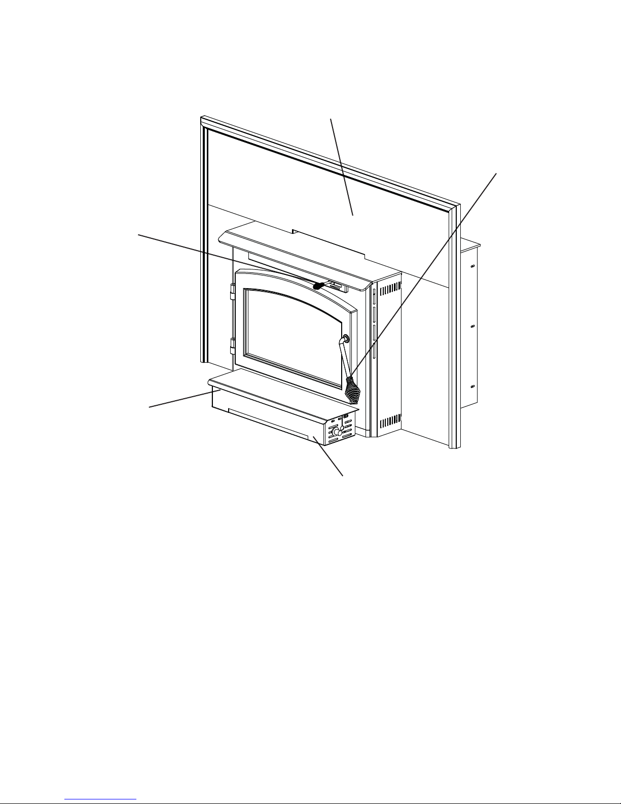
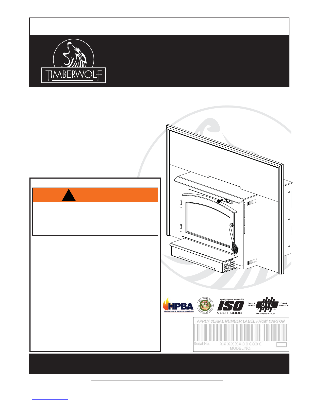
1.0 INSTALLATION OVERVIEW
Flashing, see “FLASHING
INSTALLATION” section.
Draft, see “AIR
CONTROL” section.
3
Door, see “DOOR
AND HANDLE
INSTALLATION”
section.
Rating plate, see
“RATING PLATE
INFORMATION”
section.
Blower, see “BLOWER INSTALLATION”
section.
W415-0890 / A / 04.28.10
Page 4

4
2.0 INTRODUCTION
• THIS APPLIANCE IS HOT WHEN OPERATED AND CAN CAUSE SEVERE BURNS IF CONTACTED.
• Do not operate appliance before reading and understanding operating instructions. Failure to operate
appliance according to operating instructions could cause fi re or injury.
• Before installing this appliance, contact the local building or fi re authority and follow their guidelines.
• This appliance must be installed by a qualifi ed installer.
• Risk of burns. The appliance should be turned off and cooled before servicing.
• Do not let the appliance become hot enough for any part to glow red.
• Do not install damaged, incomplete or substitute components.
• Risk of cuts and abrasions. Wear protective gloves and safety glasses during installation. Sheet metal
edges may be sharp.
• Young children should be carefully supervised when they are in the same room as the appliance. Toddlers, young children and others may be susceptible to accidental contact burns. A physical barrier is
recommended if there are at risk individuals in the house. To restrict access to an appliance or stove,
install an adjustable safety gate to keep toddlers, young children and other at risk individuals out of the
room and away from hot surfaces.
• Clothing or other fl ammable material should not be placed on or near the appliance. Objects placed in
front of the appliance must be kept a minimum of 48” away from the front face of the appliance.
• Due to high temperatures, the appliance should be located out of traffi c and away from furniture and
draperies.
• Ensure you have incorporated adequate safety measure to protect infants/toddlers from touching hot
surfaces.
• Even after the appliance is out, the glass and/or screen will remain hot for an extended period of time.
• Check with your local hearth specialty dealer for safety screens and hearth guards to protect children
from hot surfaces. These screens and guards must be fastened to the fl oor.
• Any safety screen or guard removed for servicing must be replaced prior to operating the appliance.
• Under no circumstances should this appliance be modifi ed.
• Do not operate the appliance with the glass door removed, cracked or broken. Replacement of the glass
should be done by a licensed or qualifi ed service person.
• Do not strike or slam shut the appliance glass door.
• Operate only with the doors tightly closed.
• Only doors / optional fronts certifi ed with the unit are to be installed on the appliance.
• Keep the packaging material out of reach of children and dispose of the material in a safe manner. As
with all plastic bags, these are not toys and should be kept away from children and infants.
• If the appliance is not properly installed, a house fi re may result. Do not expose the appliance to the elements
(ex. rain, etc.) and keep the appliance dry at all times. Wet insulation will produce an odour when the appliance
is used.
• The chimney must be sound and free of cracks. Clean your chimney a minimum of twice a year and as required.
• Do not start a fi re with chemicals or fl uids such as gasoline, engine oil, etc.
• Your appliance requires periodic maintenance and cleaning. Failure to maintain your appliance may lead to
smoke spillage in your home.
• Higher effi ciencies and lower emissions generally result when burning air dried seasoned hardwoods,
as compared to softwoods or too green or freshly cut hardwoods. Burning wet unseasoned wood can
cause excessive creosote accumulation. When this is ignited it can cause a chimney fi re that may result
in a serious house fi re.
• This appliance is designed to burn natural wood only. Do not burn treated wood, coal, charcoal, coloured paper, cardboard, solvents or garbage.
• Burn wood behind the log retainer directly on the fi rebricks. Do not elevate grate or otherwise raise the
fi re.
• Do not store wood within appliance installation clearances or within the space required for re-fueling
and ash removal.
!
WARNING
3.17A
W415-0890 / A / 04.28.10
Page 5
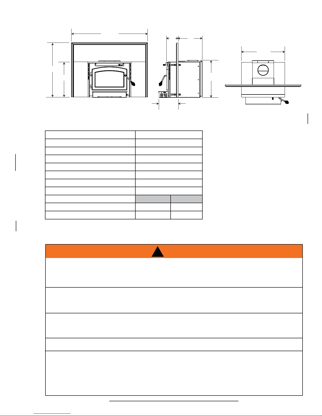
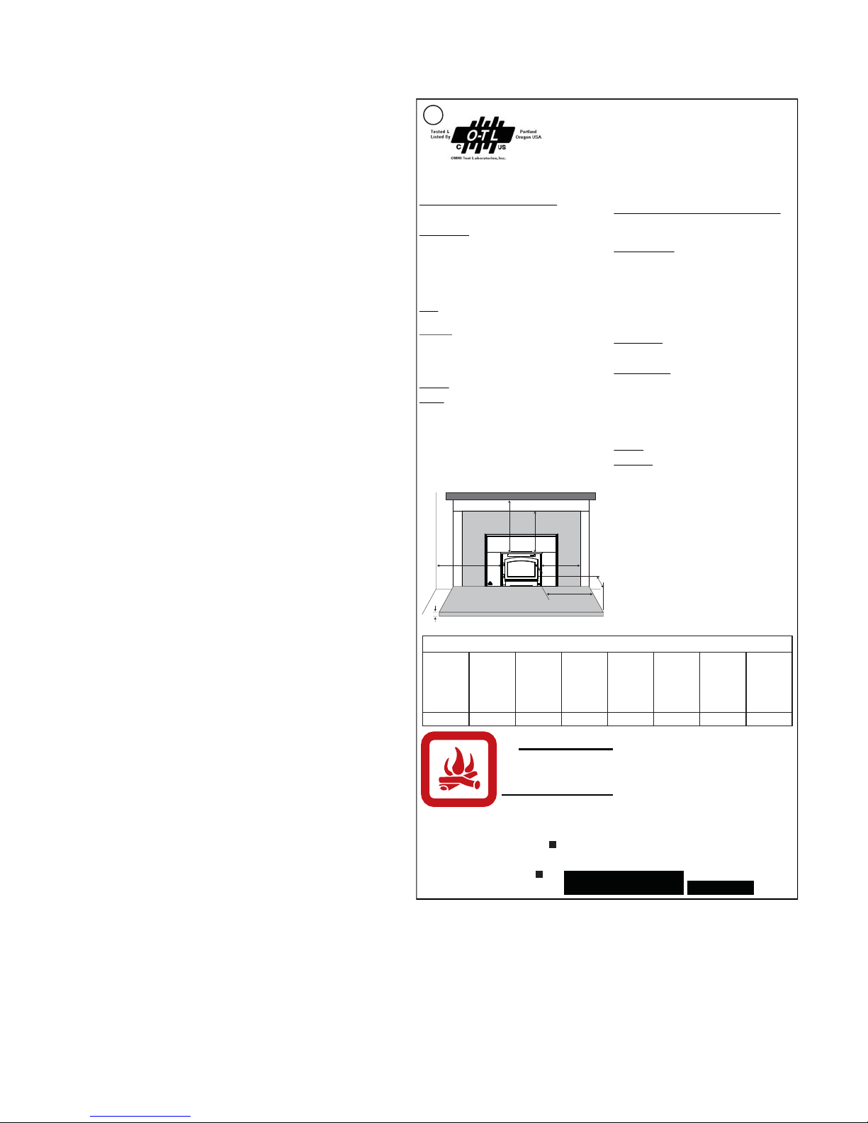
2.1 DIMENSIONS (COMPLETE WITH FLASHING)
7
44
31
3
/4"
20
/16"
5
/8"
11
A
1
/16"
*
B
* A and B are adjustable in 3/8” increments (see min max below).
2.2 SPECIFICATIONS
Specifi cations 2201
CHAMBER (D.W.H) 14 5/8” x 20 7/8” x 11 5/8”
CAPACITY 1.9 ft
APPROX. AREA HEATED** 800-1800 ft
HEAT OUTPUT (HIGH BURN) *** 60,000 BTU
DURATION LOW FIRE* 8 Hours
WEIGHT w/o BRICKS 225 lbs
WEIGHT OF BRICKS 60 lbs
AB
MIN DEPTH 7 1/2” 14”
MAX DEPTH 4” 17 1/2”
** Figures will vary considerably with individual conditions.
*** Wolf Steel Ltd. estimated realistic BTU/hr with hardwood logs and regular refueling.
3
2
5
*
3
25
/8"
3
21
/4"
2.3 GENERAL INSTRUCTIONS
ALL WIRING SHOULD BE DONE BY A QUALIFIED ELECTRICIAN AND SHALL BE IN COMPLIANCE WITH
LOCAL CODES. IN THE ABSENCE OF LOCAL CODES, USE THE CURRENT CSA22.1 CANADIAN
ELECTRIC CODE IN CANADA OR THE CURRENT NATIONAL ELECTRIC CODE ANSI/NFPA NO. 70 IN
THIS APPLIANCE HAS NOT BEEN TESTED WITH ANY VENTED OR UNVENTED GAS LOG SET. TO
REDUCE RISK OF FIRE OR PREVENT INJURY, DO NOT INSTALL A VENTED OR UNVENTED GAS LOG
BURNING YOUR UNIT WITH THE ASH DUMP DOOR OPEN OR AJAR CREATES A FIRE HAZARD THAT
MAY RESULT IN DISCOLOURATION TO THE GOLD PLATED DOOR, INTERNAL DAMAGE TO THE
APPLIANCE OR A HOUSE CHIMNEY FIRE.
DO NOT CONNECT THIS APPLIANCE TO A CHIMNEY FLUE SERVING ANOTHER APPLIANCE.
THIS APPLIANCE AND IT’S COMPONENTS ARE DESIGNED TO BE INSTALLED AND OPERATED AS A
SYSTEM. ANY ALTERATION TO OR SUBSTITUTION FOR ITEMS IN THIS SYSTEM, UNLESS ALLOWED
BY THESE INSTALLATION INSTRUCTIONS, WILL VOID THE LISTING AND MAY VOID THE PRODUCT
WARRANTY. IT MAY ALSO CREATE A HAZARDOUS INSTALLATION. READ THROUGH THESE
INSTRUCTIONS THOROUGHLY BEFORE STARTING YOUR INSTALLATION AND FOLLOW THEM
CAREFULLY THROUGHOUT YOUR PROJECT.
!
WARNING
THE UNITED STATES.
SET INTO THE APPLIANCE.
4.7
W415-0890 / A / 04.28.10
Page 6
6
• Before beginning your installation, consult with your local building code agency or fi re offi cials and
insurance representative to ensure compliance.
• Non-toxic smoke will be emitted during the paint curing process, to help dissipate the smoke open a
window near the appliance.
• Remove any dust or debris off the top of the appliance before fi ring the appliance as the paint will be-
come soft as the appliance heats up and will harden as the appliance cures. To cure the paint on your
appliance burn your appliance moderately hot during the fi rst few fi res.
• To keep the gasket from sticking to the appliance as the paint is curing, periodically open the door
every 5-10 minutes.
• For the fi rst two weeks use generous amounts of fuel and burn the appliance with the damper wide
open for an hour as the appliance goes through a process of eliminating moisture in the steel and fi re-
bricks. The initial heat output will be reduced while the moisture is bring drawn from the appliance and
it will be necessary to build several hot fi res to remove this moisture. DURING THIS PROCESS DO
NOT OVERFIRE THE APPLIANCE. REDUCE THE AMOUNT OF AIR COMING INTO THE APPLIANCE IF THE APPLIANCE OR CHIMNEY BECOMES RED.
2.4 GENERAL INFORMATION
Your appliance was specifi cally designed to meet the 1990 U.S.A. EPA particulate emission standards and
have been extensively tested in Canadian and American laboratories. This system is the most effi cient, simple
and trouble free we know and works as follows:
Y our appliance is the exact duplication of the clean-burning technology found in all T imberwolf® EPA certifi ed free-
standing stoves. External modifi cations have been made to allow its installation as a “functional insert” with a heat
circulating blower system and a means of enclosing the solid fuel burning fi replace cavity for greater heating effi ciency.
Y our appliance must be installed only into a solid fuel burning fi replace that is at least 14” deep 25 7/8” wide and 22”
high with an approved lined chimney at least 15 feet high (4.6m) and a hearth of 18”. This minimum recess can only be
achieved if the opening height is suffi cient enough to allow the connector to fi t under the noncombustible facing. The
appliance and chimney must be constructed in accordance with all national and local building code standards.
The chimney vent system used on your wood burning appliance should be designed with the least amount of
restriction possible to enable the exhaust products to easily fl ow through it. Chimney vent systems that are too
short or too long can also have an adverse affect on the fl ow of exhaust through it. The wood burning appliance
and chimney vent system also require a suffi cient supply of combustion air not only to support the combustion in the
combustion chamber but to replace the exhaust leaving it so it can fl ow freely up through the vent system and out
into the atmosphere. It is the correct balance of combustion air and the chimney vent system that will ensure the appliance provides you with its optimum
performance.
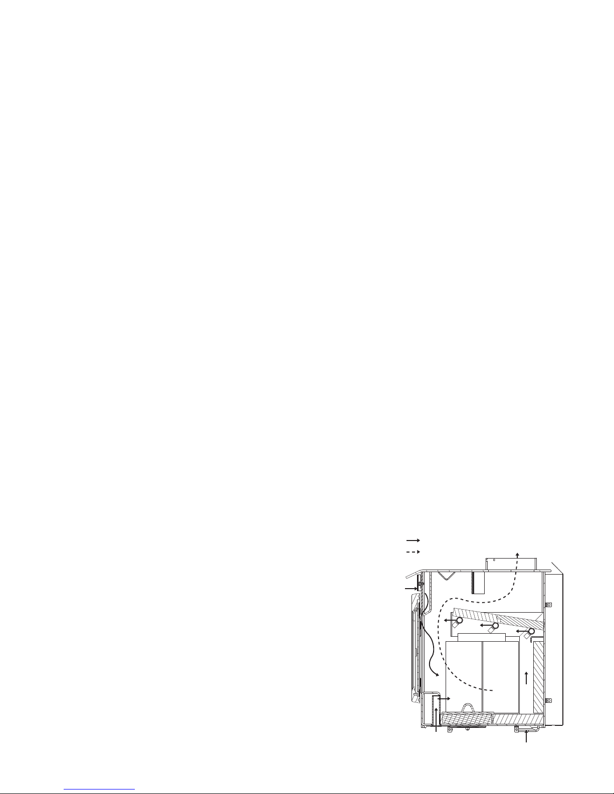
AIR INLET PATH
EXHAUST PATH
Secondary air from the rear intake opening travels up the back in the secondary air housing to the manifold located across the top and fl ows out laterally to
oxidize the gases below the smoke exit.
The lower combustion chamber is lined with high temperature fi rebricks on
2 sides, the back and across the bottom, with a layer of fi bre baffl es at the
top to maintain a high temperature in the combustion chamber so that gases
mixing with the preheated air from the secondary air manifold tube are easily
ignited and burned. The appliance sides and back are shielded to direct the
heat upwards and forwards into the room.
Be sure to provide suffi cient combustion air. There are many other ap-
pliances in your home competing for air such as: a kitchen range hood,
forced air heating devices or a bathroom exhaust fan.
W415-0890 / A / 04.28.10
Page 7

We suggest that our woodburning hearth products
be installed and serviced by professionals who are
certified in the U.S. by the National Fireplace
Institue® (NFI) as NFI Woodburning Specialists or
who are certified in Canada by
Wood Energy Technical
Training (WETT).
Expansion / contraction noises during heating up and cooling down cycles are normal and to be expected.
After extended periods of non-operation such as following a vacation or a warm weather season, the appliance
may emit a slight odour for a few hours. This is caused by dust particles on the fi rebox burning off. Open a
window to suffi ciently ventilate the room.
CALIFORNIA PROP 65 WARNING:
Use of this product may produce smoke which contains chemicals known to the State of California to cause
cancer, birth defects, or other reproductive harm.
If you experience smoking problems, you may need to open a door, a window or otherwise provide some
method of supplying combustion air to the appliance.
7
W415-0890 / A / 04.28.10
Page 8
8
2.5 RATING PLATE LOCATION
For rating plate location, see “INSTALLATION
OVERVIEW” section.
LISTED SOLID FUEL BURNING FIREPLACE INSERT
ENCASTRÉ À CO MBUSTI BLE SOLI DE HOMO LOGUÉ
REPORT NO. 415-S-08-2
INSTALL AND USE ONLY IN ACCORDANCE WITH THE
MANUFACTURER’S INSTRUCTIONS AND LOCAL BUILDING CODES.
MINIMUM CEILING HEIGHT: 7FT (2.13m)
HEARTH EXTENSION / FLOOR PROTECTION: MUST BE
NON-COMBUSTIBLE AND EXTEND 22" IN FRONT OF THE
INSERT AND 8" ON BOTH SIDES WITH A MINIMUM
THICKNESS OF .500" (K=0.84)
CHIMNEY TYPE: MINIMUM 6” (152mm) DIAMETER APPROVED
RESIDENTIAL TYPE FOR MOBILE HOME USE A CHIMNEY
LISTED TO ULC S629 IN CANADA OR UL 103HT IN THE USA.
DO NOT OBSTRUCT SPACE UNDER HEATER.
SPECIAL METHODS ARE REQUIRED WHEN PASSING A
CHIMNEY THROUGH A WALL OR CEILING. SEE INSTRUCTIONS AND BUILDING CODES.
DO NOT CONNECT THIS UNIT TO A CHIMNEY FLUE SERVING
ANOTHER APPLIANCE.
FUEL: FOR USE WITH SOLID WOOD FUEL ONLY. DO NOT
USE GRATE OR ELEVATE FIRE. BUILD WOOD FIRE DIRECTLY
ON HEARTH.
WARNING: RISK OF SMOKE SPILLAGE. OPERATE ONLY WITH
DOOR FULLY CLOSED.
REPLACE GLASS ONLY WITH CERAMIC GLASS.
DO NOT OVERFIRE. IF HEATER OR CHIMNEY CONNECTORS
GLOW, YOU ARE OVERFIRING. INSPECT AND CLEAN
CHIMNEY FREQUENTLY. UNDER CERTAIN CONDITIONS OF
USE CREOSOTE BUILD-UP MAY OCCUR RAPIDLY.
DANGER: RISK OF ELECTRICAL SHOCK. DISCONNECT
POWER BEFORE SERVICING UNIT.
INSERT: INSTALL AND USE ONLY IN SOLID FUEL BURNING
FIREPLACES. DO NOT REMOVE BRICKS OR MORTAR FROM
SOLID FUEL BURNING FIREPLACE. INSTALL WITH A
POSITIVE FLUE CONNECTOR AND FACEPLATE.
CONTACT LOCAL BUILDING FIRE OFFICIALS ABOUT RESTRICTIONS AND INSTALLATION INSPECTION IN YOUR AREA.
A MINIMUM CLEARANCE OF 18” (457mm) TO THE CHIMNEY
CONNECTOR MAY BE REQUIRED BY THE AUTHORITY
HAVING JURISDICTION.
B
C
A
F
D
E
G
TESTED TO: / TESTÉ SELON :
UL1482 / ULC S628
MODEL / MODÈLE: 2201
POUR INSTALLATION ET UTILISATION CONFORM
AUX INSTRUCTIONS DU FABRICANT ET AUX CODES
LOCAUX DU BÂTIMENT.
HAUTEUR DE PLAFOND MINIMAL: 7PI (2,13m).
BASE DE PROTECTION/PROTECTION DE PLANCHER :
DOIT ÊTRE DE NATURE INCOMBUSTIBLE ET SE
PROLONGER DE 22" À L’AVANT DE L’ENCASTRÉ ET 8"
SUR LES CÔTÉS, ET AVOIR UNE ÉPAISSEUR MINIMALE
DE 0,500" (K = 0,84).
TYPE DE CHIMNÉE: DIAMÈTRE MINIMAL DE 6” (152mm)
APPROUVÉE POUR USAGE RÉSIDENTIEL. MAISON
MOBILE EMPLOYEZ UNE CHEMINÉE HOMOLOGUÉE ULC
S629 AU CANADA OU UL 103HT AUX ÉTATS-UNIS.
NE RIEN ENTREPOSER SOUS L’APPAREIL.
DES MÉTHODES SPÉCIALES SONT REQUISES
LORSQU’UNE CHEMINÉE TRAVERSE UN MUR OU UN
PLAFOND. VOIR LES INSTRUCTIONS ET LES CODES DU
BÂTIMENT.
NE PAS RACCORDER À LA CHEMINÉE D’UN AUTRE
APPAREIL.
COMBUSTIBLE: POUR USAGE AVEC LE BOIS
SEULEMENT. N’UTILISEZ PAS DE CHENET OU NE
SURÉLEVEZ PAS LE BOIS. PRÉPAREZ LE FEU DIRECTEMENT SUR L’ÂTRE.
AVERTISSEMENT: RISQUE D’ÉCHAPPEMENT DE FUMÉE.
TENIR LA PORTE FERMÉE LORSQUE LE POÊLE
FONCTIONNE. REMPLACEZ LA VITRE PAR UNE VITRE EN
CÉRAMIQUE SEULEMENT.
NE SURCHAUFFEZ PAS L’APPAREIL. SI L’APPAREIL OU
LES RACCORDS ROUGEOIENT, L’APPAREIL
SURCHAUFEE. INSPECTEZ ET NETTOYEZ LA CHEMINÉE
FRÉQUEMMENT. DANS CERTAINES CONDITIONS, DES
DÉPÔTS DE CRÉOSOTE PEUVENT SE FORMER
RAPIDEMENT.
DANGER: RISQUE DE SECOUSSE ÉLECTRIQUE.
DÉBRANCHEZ AVANT DE PROCÉDER À L’ENTRETIEN.
ENCASTRÉ: INSTALLEZ ET UTILISEZ SEULEMENT DANS
UN FOYER À COMBUSTIBLE SOLIDE. NE RETIREZ PAS DE
MORTIER, NI BRIQUES DU FOYER À COMBUSTIBLE
SOLIDE.
INSTALLEZ AVEC UNE GAINE CONFORME ET UNE
PLAQUE DE RECOUVREMENT.
RENSEIGNEZ-VOUS AUPRÈS DES AUTORITÉS LOCALES
DU BÂTIMENT ET DU SERVICE DES INCENDIES AU SUJET
DES RESTRICTIONS ET DES INSPECTIONS
D’INSTALLATION DANS VOTRE RÉGION.
UN DÉGAGEMENT MINIMAL DE 18” (457mm) JUSQU’AU
RACCORD DE LA CHEMINÉE PEUT ÊTRE EXIGÉ PAR
L’AUTORITÉ AYANT JURIDICTION.
ÉMENT
CLEARANCE TO COMBUSTIBLE CONSTRUCTION / DÉGAGEMENTS AUX MATÉRIAUX COMBUSTIBLES:
UNIT /
APPAREIL
2201 8”1”22”10”22”30”16”
ADJACENT
SIDE WALL
(TO SIDE) /
MUR LATÉRAL
ADJACENT (AU
CÔTÉ)
MANTLE
(TO TOP) /
MANTEAU
(JUSQU’AU
DESSUS)
A
CAUTION:
ATTENTION:
MADE IN / FABRIQUÉ AU:
WOLF STEEL LTD.
BARRIE, ONTARIO CANADA
24 NAPOLEON ROAD,
BARRIE, ON, L4M 4Y8 CANADA
NAC GUANGZHOU P .R.C.
NO.69 HEFENG ROAD,
GUANGZHOU,CHINA
(MEASURED TO UNIT / À PARTIR DE L’APPAREIL)
TOP FACING
(TO TOP) /
HAUT DE LA
(JUSQU’AU
B
SIDE FACING
(TO SIDE) /
FAÇADE
CÔTÉ DE LA
FAÇADE (AU
DESSUS)
conforme à la norme d’émanation de particules de juillet 1992.
COTÉ)
C
HOT WHILE IN OPERATION. DO NOT
TOUCH. KEEP CHILDREN CLOTHING AND
FURNITURE AW A Y . CONT ACT MA Y CAUSE
SKIN BURNS.
QUAND L’APP AREIL FONCTIONNE, LA
SURFACE DEVIENT CHAUDE. NE P AS
TOUCHER. TENIR LES ENFANTS, LES
VÊTEMENTS ET LES MEUBLES À
L’ÉCART . LE CONT ACT PEUT CAUSER
DES BRÛLURES À LA PEAU .
U.S. ENVIRONMENTAL PROTECTION AGENCY
TI-2201
MINIMUM
HEARTH
EXTENSION /
BASE DE
PROTECTION
MINIMALE
D
E
DATE CODE / DE DATE
MINIMUM
HEARTH
THICKNESS /
ÉPAISSEUR
MINIMALE DE LA
BASE DE
PROTECTION
F
MINIMUM
HEARTH SIDE
EXTENSION /
BADE DE
PROTECTION
LATÉRALE
MINIMALE
G
Certifié
W385-0504
W415-0890 / A / 04.28.10
Page 9
3.0 INSTALLATION PLANNING
Clean all ashes out of the inside of the existing fi replace opening. Make sure that the chimney and fi replace are
free of cracks, loose mortar, creosote deposits, blockage or other signs of deterioration. If necessary, have any
repair work done by a qualifi ed professional before installing the insert.
Do NOT remove bricks or mortar from the fi replace. In case of an outside air inlet or ash dump, fi ll with fi ber-
glass insulation. Adhere to minimum clearances as illustrated.
Combustible material must not protrude more than 1” to the side of the insert or between the mantel and the
top of the insert.
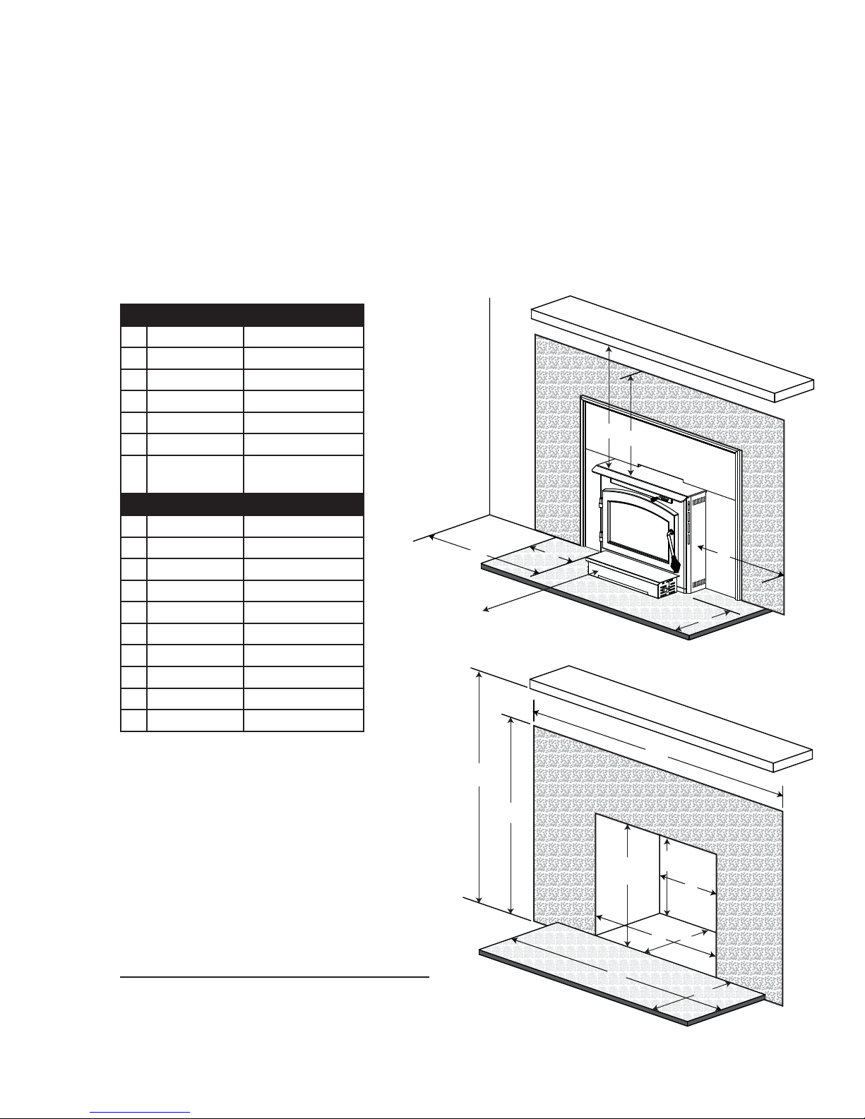
3.1 MINIMUM CLEARANCE TO COMBUSTIBLES
9
MINIMUM CLEARANCES
A Sidewall 16”
B Mantel 30”
C Top facing 22”
D Side facing 10”
E Hearth (front) 22”
F Hearth (side) 8”
G In front of
insert
MINIMUM APPLIANCE SIZE
H Width (rear) 25 7/8”
I Width (front) 25 7/8”
J Height (front) 22”
K Height (rear) 22”
L Depth 14”
M Hearth depth 18”
N Hearth width 41 7/8”
O Facing width 45 7/8”
P Facing height 47 7/8”
Q Mantel 52 5/8”
48”
SIDEWALL
G
COMBUSTIBLE MANTEL
NON-COMBUSTIBLE
B
C
A
F
NON-COMBUSTIBLE
HEARTH AND THERMAL
FLOOR PROTECTOR
COMBUSTIBLE MANTEL
FACING
D
E
HEARTH EXTENSION / FLOOR PROTECTION:
Must be non-combustible and extend 22” in front
of the insert and 8” on both sides with a minimum
thickness of .500” and a thermal conductivity factor (K) 0.84.
Q
P
NON-COMBUSTIBLE
HEARTH AND THERMAL
FLOOR PROTECTOR
NON-COMBUSTIBLE
N
O
FACING
J
I
K
H
L
M
W415-0890 / A / 04.28.10
Page 10

10
4.0 INSTALLATION
WEAR GLOVES AND SAFETY GLASSES FOR PROTECTION.
CAREFULLY FOLLOW THE INSTRUCTIONS FOR ASSEMBLY OF THE PIPE AND OTHER PARTS
NEEDED TO INSTALL THE APPLIANCE. FAILURE TO DO SO MAY RESULT IN A FIRE, ESPECIALLY IF
COMBUSTIBLES ARE TOO CLOSE TO THE APPLIANCE OR CHIMNEY AND AIR SPACES ARE
BLOCKED, PREVENTING THE FREE MOVEMENT OF COOLING AIR.
DO NOT DRAW OUTSIDE AIR FROM GARAGE SPACES. EXHAUST PRODUCTS OF GASOLINE ENGINES ARE
DO NOT INSTALL OUTSIDE AIR DUCTS SUCH THAT THE AIR MAY BE DRAWN FROM ATTIC SPACES, BASEMENTS
OR ABOVE THE ROOFING WHERE OTHER HEATING APPLIANCES OR FANS AND CHIMNEYS EXHAUST OR UTILIZE
AIR. THESE PRECAUTIONS WILL REDUCE THE POSSIBILITY OF APPLIANCE SMOKING OR AIR FLOW REVERSAL.
THE OUTSIDE AIR INLET MUST REMAIN CLEAR OF LEAVES, DEBRIS ICE AND/OR SNOW. IT MUST BE UNRE-
STRICTED WHILE APPLIANCE IS IN USE TO PREVENT ROOM AIR STARVATION WHICH CAN CAUSE SMOKE SPILL-
AGE AND AN INABILITY TO MAINTAIN A FIRE. SMOKE SPILLAGE CAN ALSO SET OFF SMOKE ALARMS.
NEGATIVE PRESSURE WITHIN YOUR HOME MAY INADVERTENTLY AFFECT YOUR APPLIANCE.
!
WARNING
HAZARDOUS.
TO PREVENT CONTACT WITH SAGGING OR LOOSE INSULATION, THE APPLIANCE MUST NOT BE INSTALLED
AGAINST VAPOUR BARRIERS OR EXPOSED INSULATION. LOCALIZED OVERHEATING COULD OCCUR AND A FIRE
COULD RESULT.
DO NOT USE MAKESHIFT COMPROMISES DURING INSTALLATION. DO NOT BLOCK OR RESTRICT AIR, GRILLE OR
LOUVRE OPENINGS. DO NOT ADD A HOOD.
KEEP HAND TOOLS IN GOOD CONDITION, SHARPEN CUTTING EDGES AND MAKE SURE TOOL HANDLES ARE
SECURE.
ALWAYS MAINTAIN THE MINIMUM AIR SPACE REQUIRED TO THE ENCLOSURE TO PREVENT FIRES.
68.3A
It is extremely important that your appliance be installed according to the manufacturer's specifi cations. The
manufacturer's installation instructions and specifi ed clearances should always be followed in accordance with
local and national codes. In Canada the CSA B365 and the CSA C22.1 installation codes are to be followed. In
the USA the ANSI NFPA 70 and ANSI NFPA 211 installation codes are to be followed.
Chimney and liner must be in good condition and kept clean.
W415-0890 / A / 04.28.10
Page 11
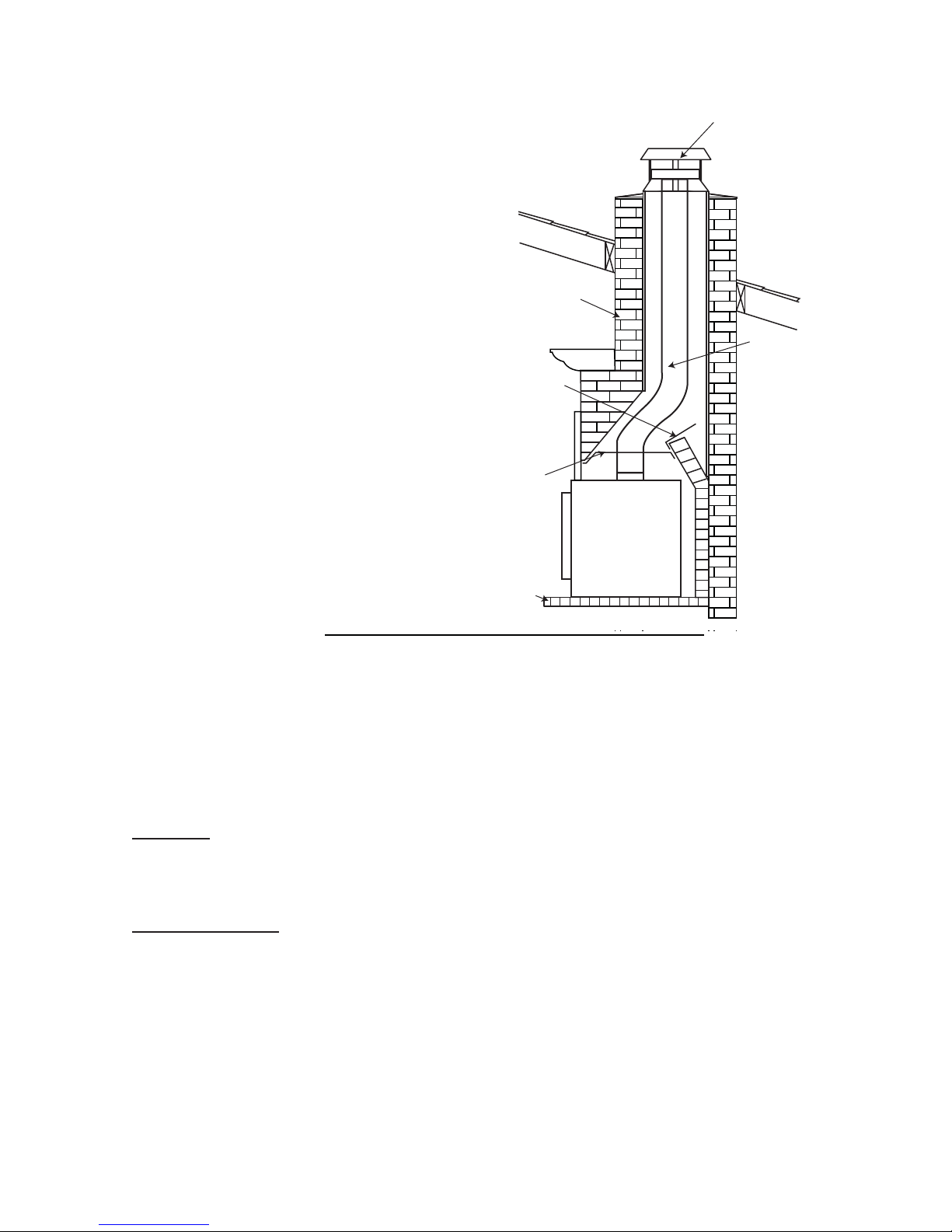
4.1 TYPICAL EXISTING MASONRY
You can install your appliance using your existing masonry chimney. To do
so, follow the guidelines below. If you are using a masonry chimney, it
is important that it be built in compliance with the specifi cations of the
Building Code in your region. It must normally be lined with fi re clay
bricks, metal or clay tiles sealed together with fi re cement. (Round
fl ues are the most effi cient).
DAMPER PLATE
REMOVED OR
FASTENED IN OPEN
POSITION
SEAL WITH NONCOMBUSTIBLE
MATERIAL
11
FOLLOW MANUFACTURER’S
INSTRUCTIONS FOR
MAXIMUM LINER EXTENSION
ABOVE CHIMNEY
MASONRY CHIMNEY MUST HAVE
STRUCTURAL
INTEGRITY
LISTED
CHIMNEY
LINER
FLOOR
PROTECTOR
62.2
A. Remove the fi replace damper or fasten it permanently open.
* We recommend the following method of sealing off the damper area around the liner.
B. * Measure the throat of the fi replace and mark this shape on a piece of 24 gauge sheet metal (fl ue
cover); cut a six-inch (6.75”) hole to lie directly below the fi replace fl ue opening. Allow two inches of
material for a fl ange on all sides and cut to these measurements. Bend down the fl anges. If you have
never done this before, it might be a good idea to make a cardboard pattern and test it fi rst. Fasten this
fl ue cover in position as high as possible with two masonry screws per side through the fl anges into the
fi replace.
In Canada: Install a listed 6 inch diameter fl exible stainless steel liner from the top of the chimney to the insert
fl ue collar. Attach a stainless steel liner connector or elbow to the liner and insert onto the fl ue collar. Fasten with
three screws. Secure the top of the liner to the chimney cap using a liner support and chimney fl ashing. Cap the
top of the chimney liner assembly using an approved rain cap.
In the United States: While it is not required, it is recommended that a chimney liner be installed that is continuous from the insert to the top of the chimney , particularly when the insert is installed in a basement. For this type
of connection, use the “In Canada” installation instructions above.
If a continuous liner is not installed, a “direct fl ue connection” must be made. The direct fl ue connection requires a
non-combustible connector that extends from the insert into the chimney fl ue liner and also that the installed fl ue
cover be sealed below the entry point of the connector to prevent dilution of combustion products in the chimney
fl ue with air from inside the house. Cap the top of the chimney using an approved rain cap.
The following installation requirements must be observed when installing solid fuel burning inserts into factory
built fi replaces.
W415-0890 / A / 04.28.10
Page 12

12
4.2 FACTORY BUILT FIREPLACE
The following installation requirements must be observed when installing solid fuel burning inserts into factory
built fi replaces.
A. The factory built fi replace must be listed per UL 127 or ULC S610.
B. Clearances to any combustible material surrounding this insert as identifi ed must be followed. These
clearance requirements supersede any pre-existing facing material clearances listed for the factory
built fi replace.
C. Installation must include a full height listed chimney liner meeting HT requirements (2100°F) as re-
quired in UL 1777 (U.S.) or ULC S635 (Canada). The liner must be securely attached to the insert fl ue
collar and the chimney top.
D. Means must be provided to prevent room air passage to the chimney cavity of the fi replace. This may
be accomplished by sealing the damper area around the chimney liner, or sealing the appliance front.
E. The air fl ow within and around the appliance shall not be altered by the installation of the insert (i.e.
no louvres or cooling air inlet or outlet ports are blocked), unless specifi cally tested as such for each
factory built fi replace manufacturer and model line. NOTE: Using a louvered face plate (surround)
complies with this requirement.
F. Alteration of the appliance in any manner is not permitted with the following exceptions;
A. External trim pieces which do not affect the operation of the appliance may be removed providing
they can be stored on or within the fi replace for reassembly if the insert is removed.
B. The chimney damper may be removed to install the chimney liner.
G. Circulating air chambers (i.e. in a steel fi replace liner or metal heat circulator) shall not be blocked.
H. Means must be provided for removal of the insert to clean the chimney fl ue.
I. Inserts that project in front of the fi replace must be supplied with appropriate support means.
J. A permanent metal warning label must be attached to the back of the fi replace stating that the fi replace
must be restored to its original condition for safe use without the insert.
80.2A
W415-0890 / A / 04.28.10
Page 13

5.0 FINISHING
HOLE
5.1 SECONDARY AIR TUBES
5.1.1 Start at the back working forwards, install the secondary
air tube by inserting the tube into the hole,
as illustrated in “A”.
5.1.2 Slide the tube into the opposite hole.
With the holes on the secondary air
tube pointing forward, align
the tube with the tube
retainer and insert
the cotter pin, as
illustrated in“B”.
13
A
B
5.1.3 Spread the cotter pin
to retain.
NOTE: There are 4 secondary air tubes. One of the
tubes has larger holes. This
tube is to be located closest
to the front of the appliance,
as illustrated in “C”.
TUBE
RETAINER
COTTER PIN
C
W415-0890 / A / 04.28.10
Page 14
14
5.2 BRICKS AND BAFFLES INSTALLATION
!
WARNING
OPERATION OF THE APPLIANCE WITHOUT THE BAFFLES CAN RESULT IN EXCESSIVE TEMPERA-
TURES THAT COULD DAMAGE THE APPLIANCE, CHIMNEY AND THE SURROUNDING ENCLOSURE.
With the appliance and chimney installation completed, move the bricks into place as illustrated below.
5.2.1 Install the bottom nine (A) bricks and one (B) brick, working from the back of the appliance forward as
illustrated.
5.2.2 Install four (A) bricks along both sides of the appliance.
5.2.3 Install the four (A) bricks and one (C) brick along the back wall by pivoting the bricks up under the brick
retainer. NOTE: Place narrow (C) brick in centre.
5.2.4 Install two (D) bricks along the front of the appliance below the ledge at the bottom of the door
opening.
5.2.5 Carefully pivot two (E) fi bre baffl es up onto the secondary air tubes as illustrated. Ensure that the top
baffl es are pushed all the way to the rear of the fi rebox, leaving a minimum of a 1 inch gap along the
front. This will allow the fl ue gases to escape the fi rebox. Ensure overlap joint is tight.
E
E
A
A
A
A
A
A
A
A
D
D
A
B
A
A
5.3 DOOR INSTALLATION
Hang the door using the hinge pins supplied.
OVERLAP
JOINT
A
A
C
A
A
A
A
A
A
A
A
BAFFLE
SECONDARY
AIR TUBES
W415-0890 / A / 04.28.10
Page 15
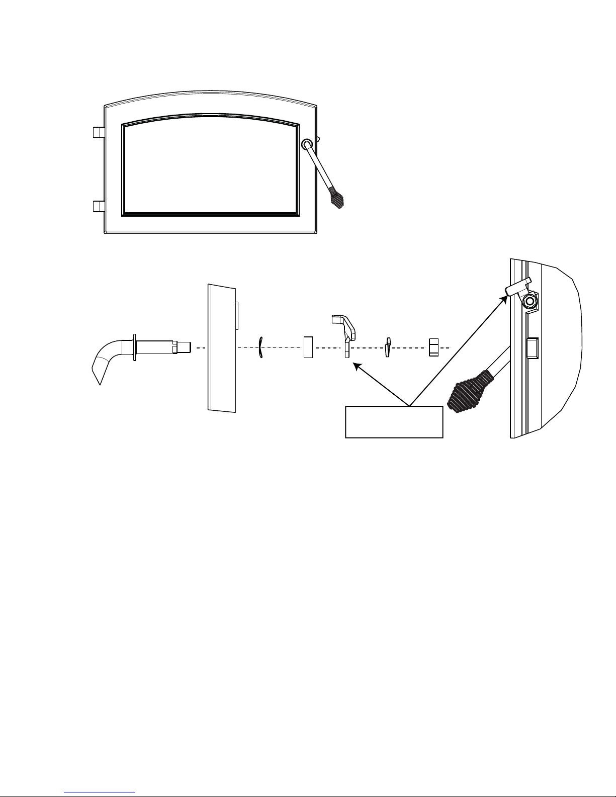
5.4 DOOR HANDLE INSTALLATION
FRONT VIEW
DOOR
DOOR HANDLE
LATCH
LOCK
WASHER
15
NUT
DOOR
HANDLE
SPRING
WASHER
SPACER
NOTE: Position of
door handle latch.
Twist the large wire handle over the end of the handle rod. T wist the smaller wire handle over the end of the air control rod
above the door.
W415-0890 / A / 04.28.10
Page 16

16
5.5 FLASHING INSTALLATION
The top and side fl ashings have been shipped fl at.
5.5.1 To install the side fl ashings, engage the tabs into the slots which will position the insert in the preferred
location.
5.5.2 Lower the top fl ashing against the appliance and secure using the clips as illustrated below.
5.5.3 Based on where the fl ashing has been installed, adjust the top chute tight against the top fl ashing and
secure in place.
5.5.4 The three pieces of trim are assembled in the same manner as a picture frame. Place the corner
brackets (with screw loosened) into the trim sections. Tighten the screw spreading the two pieces
apart. Attach the adjoining section. Repeat with the opposite side. Tighten all screws fi rmly.
5.5.5 Slide the trim over the fl ashing.
5.5.6 Install the fi ve spring clips provided by inserting them in between the trim and the back of the fl ashing
as illustrated.
NOTE: The fl ashing on this appliance is adjustable in 1/4” increments. It has been designed to accom-
modate a minimum hearth depth of 14”. Once the appliance has been installed, the fl ashing can be
adjusted back to the facing material. If desirable the appliance can be moved back into the masonry
opening as far as 17 1/2”.
4
5
2
3
6
W415-0890 / A / 04.28.10
1
Page 17
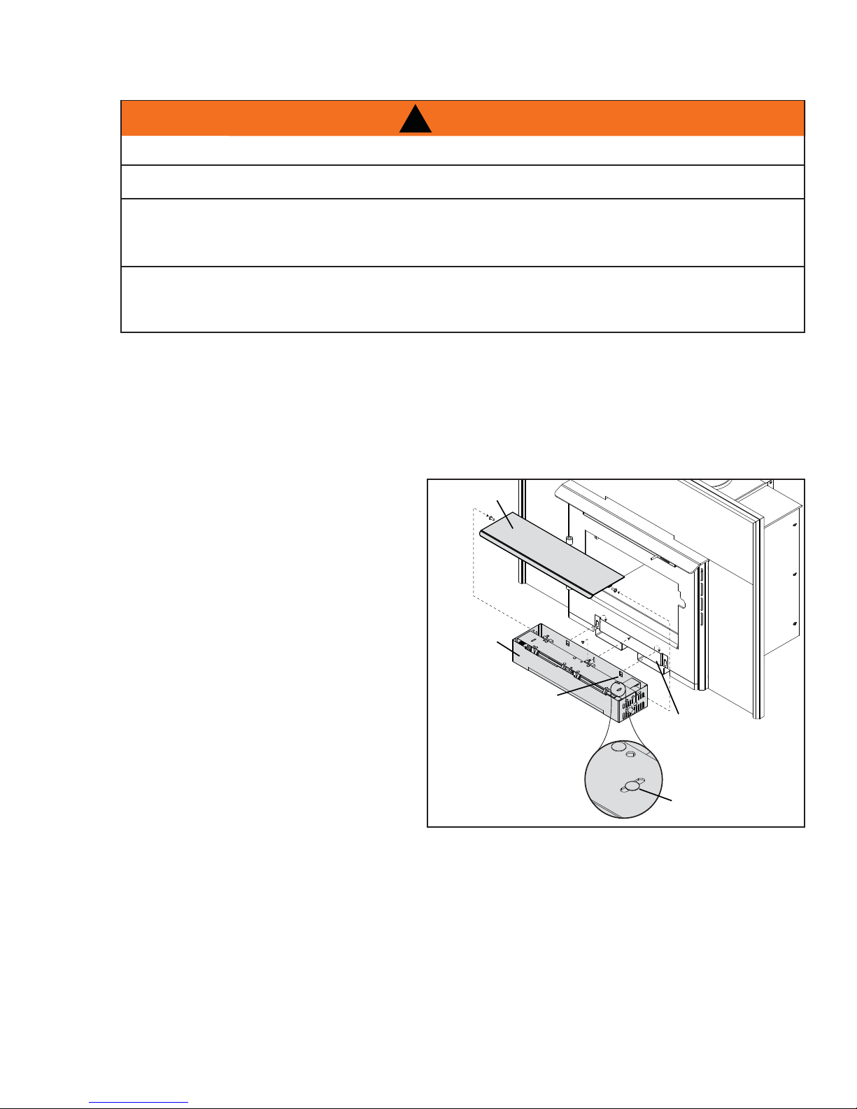
5.6 BLOWER INSTALLATION
RISK OF FIRE AND ELECTRICAL SHOCK.
TURN OFF THE ELECTRICAL POWER BEFORE SERVICING THIS APPLIANCE.
USE ONLY WOLF STEEL APPROVED OPTIONAL ACCESSORIES AND REPLACEMENT PARTS WITH
THIS APPLIANCE. USING NON-LISTED ACCESSORIES (BLOWERS, DOORS, LOUVRES, TRIMS, ETC.)
COULD RESULT IN A SAFETY HAZARD AND WILL VOID THE WARRANTY AND CERTIFICATION.
ENSURE THAT THE BLOWER’S POWER CORD IS NOT IN CONTACT WITH ANY SURFACE OF THE
APPLIANCE TO PREVENT ELECTRICAL SHOCK OR FIRE DAMAGE. DO NOT RUN THE POWER
Drywall dust will penetrate into the blower bearings, causing irreparable damage. Care must be taken to prevent drywall dust from coming into contact with the blower or its compartment. Any damage resulting from this
condition is not covered by the warranty policy. Use of the blower increases the output of heat.
This blower is thermally activated. Depending on the intensity of the fi re, the blower will start 15-30 minutes af-
ter lighting. The thermal switch for the appliance is affi xed to an adjustable bracket, which should be positioned
so it is in contact with the blower housing as illustrated.
!
WARNING
CORD BENEATH THE APPLIANCE.
17
For shipping purposes the blower housing has
been stored within the fi rebox. We recommend
removing the door prior to installing the blower.
5.6.1 Remove the two screws securing the
cover and set aside.
5.6.2 Engage the clips onto the retainer
bracket and secure using the screw
supplied.
5.6.3 Reattach the cover with the two screws
previously removed.
COVER
BLOWER
HOUSING
CLIPS
RETAINER
BRACKET
ADJUSTABLE
W415-0890 / A / 04.28.10
Page 18

18
6.0 OPERATION
ALWAYS OPERATE THIS APPLIANCE WITH THE DOOR CLOSED AND LATCHED EXCEPT DURING
START UP AND RE-FUELING. ALWAYS WEAR GLOVES TO PREVENT INJURY. DO NOT LEAVE THE
FIRE UNATTENDED WHEN THE DOOR IS UNLATCHED AS UNSTABLE WOOD COULD FALL OUT OF
THE FIRE CHAMBER CREATING A FIRE HAZARD TO YOUR HOME.
NEVER LEAVE CHILDREN UNATTENDED WHEN THERE IS A FIRE BURNING IN THE APPLIANCE.
NEVER USE GASOLINE, GASOLINE-TYPE LANTERN FUEL, KEROSENE, CHARCOAL LIGHTER FLUID,
OR SIMILAR LIQUIDS TO START OR ‘FRESHEN UP’ A FIRE IN THIS APPLIANCE. KEEP ALL SUCH
LIQUIDS WELL AWAY FROM THE APPLIANCE WHILE IT IS IN USE.
OBJECTS PLACED IN FRONT OF THE APPLIANCE SHOULD BE KEPT A MINIMUM OF 48” FROM THE
ANY MODIFICATION OF THE APPLIANCE THAT HAS NOT BEEN APPROVED IN WRITING BY THE
TESTING AUTHORITY IS CONSIDERED BREACHING CSA B365 (CANADA) AND ANSI NFPA 211 (USA).
OPEN AIR CONTROL (AND DAMPER WHEN FITTED) BEFORE OPENING FIRING DOOR.
!
WARNING
FRONT FACE.
HOT WHILE IN OPERATION, KEEP CHILDREN, CLOTHING AND FURNITURE AWAY. CONTACT MAY
CAUSE SKIN BURNS. WEAR GLOVES TO OPERATE YOUR APPLIANCE.
BURNING YOUR APPLIANCE WITH THE DOORS OPEN OR AJAR CREATES A FIRE HAZARD THAT MAY
RESULT IN A HOUSE AND OR CHIMNEY FIRE.
Y our T imberwolf EPA listed product is designed with the most advanced technology . The appliance is extremely airtight.
The fi rst fi re(s) in your appliance will be diffi cult to get going and keep going with little amount of heat being gener-
ated. This is a result of the moisture being driven out of the fi re brick. Allow 30 to 40 hours of hot fi res (temperatures in
excess of 500°F - 600°F) before your appliance will perform normally . During the break-in period (the fi rst 2 or 3 fi res)
create only small, hot fi res using kindling; this will allow the fi rebrick to cure. Do not be alarmed if small hairline cracks
develop in the fi rebrick. This is a normal occurrence and does not pose a safety hazard. The paint may also smell a
little for the fi rst few fi res as it cures and you may wish to open a door or window to alleviate the smell.
To start, a brisk fi re is required. Place loosely crumpled paper on the fl oor of the appliance and cover with dry kindling.
Open the air control fully by sliding control all the way to the right. Light the paper and leave the door slightly ajar (one
inch) until all kindling is burning. To maintain a brisk fi re, a hot coal bed must be established and sustained.
Slowly add larger wood (2x4 size pieces). Lay the pieces lengthwise from side to side in the hot coal bed with a shallow trench between, so that the primary air can fl ow directly into this trench and ignite the fuel above. When the fi re
seems to be at its peak, medium sized logs may be added. Once these logs have caught fi re, carefully close the door.
(Closing the door too quickly after refueling will reduce the fi rebox temperature and result in an unsatisfactory burn.)
Remember it is more effi cient to burn medium sized wood, briskly, and refuel frequently than to load the appliance with
large logs that result in a smouldering, ineffi cient fi re and dirty glass.
As soon as the door is closed, you will observe a change in the fl ame pattern. The fl ames will get smaller and lazier
because less oxygen is getting into the combustion chamber. The fl ames, however , are more effi cient. The fl ames will
remain lazy but become larger again as soon as the fi rebricks have been heated thoroughly and the chimney becomes
heated and provides a good draft. At this point, the roaring fi re that you see when the door is opened is wastefully
drawing heated room air up the chimney , certainly not desirable. Always operate with the door fully closed once the
medium sized logs have caught fi re.
W415-0890 / A / 04.28.10
Page 19

You can now add larger pieces of wood and operate the appliance normally. Once the appliance is entirely hot,
it will burn very effi ciently with little smoke from the chimney. There will be a bed of orange coals in the fi rebox
and secondary fl ames fl ickering just below the top baffl es. You can safely fi ll the fi rebox with wood to the top of
the door and will get best burns if you keep the appliance pipe temperatures between 250 degrees Fahrenheit
(120 degrees Celsius) and 450 degrees Fahrenheit (270 degrees Celsius). A surface thermometer will help
regulate this.
Without an appliance thermometer, you are working blindly and have no idea of how the appliance is operating!
An appliance thermometer offers a guide to performance.
Can’t get the fi re going? Use more kindling and paper. Assuming the chimney and vent are sized correctly and
there is suffi cient combustion air, the lack of suffi ciently dry quantities of small kindling is the problem. Thumb
size is a good gauge for small kindling diameter.
Can’t get heat out of the appliance? One of two things may have happened. The appliance door may have
been closed prematurely and the appliance itself has not reached optimum temperature. Reopen the door and/
or draft control to re-establish a brisk fi re. The other problem may have been wet wood. The typical symptom is
sizzling wood and moisture being driven from the wood.
6.1 AIR CONTROL
Draft is the force which moves air from the fi rebox up through the chimney.
The amount of draft in your chimney depends on the length and diameter of
chimney, local geography, nearby obstructions and other factors. Adjusting
the air control all the way to the left reduces the temperature. The draft can be
adjusted from low to high by moving the handle from left to right. Inadequate
draft may cause back-puffi ng into the room through the appliance and chimney
connector points and may cause plugging of the chimney. Too much draft may
cause an excessive temperature in the appliance, glowing red appliance parts
or chimney connectors or an uncontrollable burn which can lead to a chimney
fi re or permanent damage to the appliance. Do not operate your appliance for
longer than 30 minutes with the air control on “HIGH” (fully open).
19
AIR CONTROL
6.2 FIRE EXTINGUISHERS / SMOKE DETECTORS
All homes with a solid fuel burning appliance should have at least one fi re extinguisher in a central location
known to all and at least one smoke detector in the room containing the appliance. If it sounds an alarm, correct the cause but do not deactivate or relocate the smoke detector.
6.3 FUEL
!
WARNING
DO NOT STORE FUEL WITHIN THE CLEARANCE TO COMBUSTIBLES, OR IN THE SPACE REQUIRED
FOR RE-FUELING AND ASH REMOVAL.
BURNING WET, UNSEASONED WOOD CAN CAUSE EXCESSIVE CREOSOTE ACCUMULATION. WHEN
IGNITED IT CAN CAUSE A CHIMNEY FIRE THAT MAY RESULT IN A SERIOUS HOUSE FIRE.
When loading the appliance, ensure that the two upper fi bre baffl es are not lifted up and of f their ledge. For
maximum effi ciency, when the appliance is thoroughly hot, load it fully to the top of the door opening and burn at
a medium low setting. Maximum heat for minimum fuel (optimum burn) occurs when the appliance top temperature is between 500°F (260°C) and 600°F (315°C). The bricks will be nearly all white and the glass mostly clear .
The whiteness of the bricks and the cleanliness of the glass are good indicators of your operating effi ciency. Not
enough heat is produced when only one or two pieces of wood are burned or the wood may not burn completely .
A minimum of three pieces are needed to encase a bed of coals that sustains the fi re.
NOTE: When loading the appliance, ensure to keep fuel back from the glass. If coals are to accumulate
on the front lip, there is a chance they will fall out when the door is opened.
W415-0890 / A / 04.28.10
Page 20

20
Loosely stacked wood burns quicker than a tightly packed load. Wood burns in cycles rather than giving a steady
output of heat. It is best to plan these cycles around your household routine so that only enough coals are left to
start the next load. In the evening, load your appliance, at least, a half-hour before bed to ensure a good fi re, hot
enough to close the draft control for an overnight burn.
Burn only dry seasoned wood. It produces more heat and less soot or creosote. Do not burn ocean beach wood.
Its salt content can produce a metal eating acid. When refueling open the door slowly to prevent smoke spillage.
Use a pair of long gloves (barbecue gloves) when feeding the fi re. Because these appliances burn at the front,
they are clean and effi cient, but they are also very hot and gloves are useful. Keep a small steel shovel nearby to
use as a poker and to remove ashes. Do not store the wood within 3 feet (1m) of the appliance.
6.4 LIGHTING A FIRE
6.4.1 FLASH FIRE
A fl ash fi re is a small fi re burned quickly when you don’t need much heat. After your kindling has “caught”, load
at least 3 pieces of wood, stacked loosely. Burn with the draft control fully open or closed only slightly.
6.4.2 EXTENDED FIRE
Load your larger pieces of wood compactly, packed close enough to prevent the fl ames from penetrating it
completely.
After approximately 30 minutes, depending on the size of the load, close the draft control completely making
sure that the fi re is not extinguished.
DO NOT OVERFIRE THE APPLIANCE!
Overfi ring can occur by:
A. Burning large amounts of smaller wood pieces such as furniture scraps, skids or treated wood;
B. Vigorously burning large loads of wood with the draft control on “HIGH” (fully open) for long periods of
time (one or two hours).
C. Leaking door gaskets that will permit excess air to enter the combustion chamber.
6.5 SMOKING
A properly installed appliance should not smoke. If yours does, check the following:
• Has the chimney had time to get hot?
• Is the smoke passage blocked anywhere in the appliance, chimney connector or chimney?
• Is the room too airtight and the air intake not connected to the outside? Try with a window partly open.
• Is the smoke fl ow impeded by too long a horizontal pipe or too many bends?
• Is it a weak draft perhaps caused by a leaky chimney, a cold outside chimney, too large a diameter of
a chimney, too short a chimney, or a chimney too close to trees or a higher roof?
• Has a direct fl ue connection been used rather than a chimney liner continuous from cap to appliance
fl ue collar.
W415-0890 / A / 04.28.10
Page 21
7.0 MAINTENANCE
TURN OFF THE POWER BEFORE SERVICING THE APPLIANCE.
APPLIANCE MAY BE HOT, DO NOT SERVICE UNTIL APPLIANCE HAS COOLED.
DO NOT USE ABRASIVE CLEANERS.
Check your chimney and chimney connector for creosote and soot buildup weekly until a safe frequency for
cleaning is established.
If accumulation is excessive, disconnect the appliance and clean both the chimney and the appliance. You
may want to call a professional chimney sweep to clean them. Both have to be cleaned at least once a year or
as often as necessary.
Remove fi bre baffl es and clean above them once a year. Replace any broken bricks.
7.1 ASH REMOVAL PROCEDURES
IMPROPER DISPOSAL OF ASHES RESULT IN FIRES. DO NOT DISCARD ASHES IN CARDBOARD
BOXES, DUMP IN BACK YARDS, OR STORE IN GARAGES.
!
WARNING
!
WARNING
21
IF USING A VACUUM TO CLEAN UP ASHES, BE SURE THE ASHES ARE ENTIRELY COOLED. USING
A VACUUM TO CLEAN UP WARM ASHES COULD CAUSE A FIRE INSIDE THE VACUUM.
NEVER OPERATE YOUR APPLIANCE WITH THE GRATE COVER REMOVED.
FAILURE TO ACHIEVE A GOOD SEAL BETWEEN THE ASH OPENING, ASH PLUG OR ASH WELL DOOR
WILL RESULT IN AN OVER FIRE CONDITION THAT COULD CAUSE DAMAGE TO THE APPLIANCE.
Allow the ashes in your fi rebox to accumulate to a depth of two or three inches; they tend to burn themselves
up. When the fi re has burned down and cooled, remove any excess ashes but leave an ash bed approximately
1 inch deep on the fi rebox bottom to help maintain a hot charcoal bed.
DISPOSAL OF ASHES: Ashes should be placed in a metal container with a tight fi tting lid. The closed contain-
er of ashes should be placed on a non-combustible fl oor or ground, well away from all combustible materials,
pending fi nal disposal. If the ashes are disposed of by burial in soil or otherwise locally dispersed, they should
be retained in the closed container until all cinders have thoroughly cooled.
7.2 CREOSOTE FORMATION AND REMOVAL
When wood is burned slowly, it produces tar and other organic vapours which combine with expelled moisture
to form creosote. These vapours condense in the relatively cooler chimney fl ue of a slow burning fi re and when
ignited, make an extremely hot fi re. So, the smoke pipe and chimney should be inspected monthly during the
heating season to determine if a buildup has occurred. If creosote has accumulated it should be removed to
reduce the risk of a chimney fi re.
W415-0890 / A / 04.28.10
Page 22

22
7.3 RUNAWAY OR CHIMNEY FIRE
Runaway fi res can be the result of three major factors:
• Using incorrect fuel, or small fuel pieces which wood normally be used as kindling.
• Leaving the door ajar too long and creating extreme temperatures as the air rushes in the open door.
• Burning your appliance with the ash plug not securely seated.
SOLUTIONS:
• Do not burn treated or processed wood, coal,charcoal, coloured paper or cardboard.
• Be careful not to over-fi re the appliance by leaving the door open too long after initial start-up. A ther-
mometer on the chimney connector and/or appliance top helps.
• Always operate the appliance with the ash plug properly installed.
IN CASE OF A CHIMNEY FIRE:
• Have a well understood plan for evacuation and a place outside for everyone to meet. Prepare to
evacuate to ensure everyone’s safety.
• Close air inlet on appliance.
• Call local fi re department. Have a fi re extinguisher handy. Contact local authorities for further informa-
tion on how to handle a chimney fi re.
• After the chimney fi re is out, clean and inspect the chimney for stress and cracks prior to lighting an-
other fi re. Also check combustibles around the chimney and the roof.
7.4 CHIMNEY CLEANING
For serious wood burners, chimney cleaning must be done as needed to avoid chimney fi res; the venting sys-
tems for controlled combustion appliances may need cleaning as often as once a month. These rates, however, depend on the burning habits of the individual operating the appliance. For example, it is possible to clog
a solid fuel appliance chimney in a few days if slow, smoldering fi res are burned and the chimney is cold. Wood
burners who consistently operate their appliances with appropriately hot fi res may infrequently have signifi cant
creosote accumulations in the chimney.
Certain items and considerations are important in chimney cleaning:
• Proper tools should be used, including a brush specifi cally designed for chimney cleaning.
• The chimney connector and dampers as well as the chimney should be cleaned.
• The appliance’s fi rebox and baffl e system should be cleaned if needed.
• The chimney should be inspected and repairs made if needed, preferably by a qualifi ed chimney
sweep or mason.
W415-0890 / A / 04.28.10
Page 23

7.5 DOOR REMOVAL
BURNING YOUR APPLIANCE WITH THE DOORS OPEN OR AJAR CREATES A FIRE HAZARD THAT
Pivot the door open and lift the door and pins off the bushings. Set the door aside being careful not to scratch the paint.
!
WARNING
MAY RESULT IN A HOUSE AND OR CHIMNEY FIRE.
DO NOT STRIKE OR SLAM DOOR.
NEVER REMOVE THE DOOR WHEN THE APPLIANCE IS HOT.
23
7.6 GLASS REPLACEMENT
GLASS MAY BE HOT, DO NOT TOUCH GLASS UNTIL COOLED.
CARE MUST BE TAKEN WHEN REMOVING AND DISPOSING OF ANY BROKEN DOOR GLASS OR
DAMAGED COMPONENTS. BE SURE TO VACUUM UP ANY BROKEN GLASS FROM INSIDE THE
DO NOT STRIKE, SLAM OR SCRATCH GLASS. DO NOT OPERATE APPLIANCE WITH GLASS
REMOVED, CRACKED, BROKEN OR SCRATCHED.
7.6.1 When the appliance is cool, open the
door and place the door frame down
careful not to scratch the paint.
7.6.2 Remove the screws and brackets
holding the glass in place. Remove all
broken glass.
7.6.3 Affi x the 3/4” fl at gasket to the glass
retainers as illustrated, ensuring a 1/4”
overhang at each end.
7.6.4 Place the glass with the fi berglass gasket
in position and replace the brackets and
screws. When fi nished, you should be
able to move the glass slightly , horizontally
and vertically .
!
WARNING
DO NOT USE SUBSTITUTE MATERIALS.
APPLIANCE BEFORE OPERATION.
56.1
¾” x 3 ½”
FLAT
GASKET
¼” ROPE
GLASS
GASKET
½” ROPE
DOOR
GASKET
NOTE: For replacement glass, size, thickness
and specifi cations see “REPLACEMENTS”
section.
W415-0890 / A / 04.28.10
Page 24

24
7.7 CARE OF GLASS
If the glass is not kept clean permanent discolouration and / or
blemishes may result. Normally a hot fi re will clean the glass.
The most common reasons for dirty glass include: not using
suffi cient fuel to get the appliance thoroughly hot, using green
or wet wood, closing the draft so far that there is insuffi cient air
for complete combustion.
If it is necessary to clean the glass, buff lightly with a clean dry
cloth and non-abrasive cleaner.
DO NOT CLEAN GLASS WHEN HOT! Clean the glass after the fi rst 10 hours of operation with a
recommended appliance glass cleaner. Thereafter clean as required.
The glass is very strong but do not let burning fuel rest or fall against it and always close the door gently.
NEVER FORCE IT SHUT!
If the glass should ever crack or break while the fi re is burning, do not open the door until the fi re is out and do
not operate the appliance again until the glass has been replaced, available from your Authorized dealer. DO
NOT SUBSTITUTE MATERIALS.
7.8 CARE OF PLATED PARTS
!
WARNING
HOT GLASS WILL
CAUSE BURNS.
DO NOT TOUCH GLASS
UNTIL COOLED.
NEVER ALLOW CHILDREN
TO TOUCH GLASS.
5.3
If the appliance is equipped with plated parts, you must clean fi ngerprints or other marks from the plated
surfaces before operating the appliance for the fi rst time. Use a glass cleaner or vinegar and towel to clean.
If not cleaned properly before operating for the fi rst time, the marks can cause permanent blemishes on
the plating. After the plating is cured, the fi ngerprints and oils will not affect the fi nish and little maintenance
is required, just wipe clean as needed. Prolonged high temperature burning with the door ajar may cause
discolouration on plated parts.
NOTE: The protective wrap on plated parts is best removed when the assembly is at room
temperature but this can be improved if the assembly is warmed, using a hair dryer or similar heat
source.
7.9 GASKET REPLACEMENT
At the end of each burning season inspect the shield and gasket below the manifold for warping or deterioration. Replace if necessary. Both are held to the manifold with machine screws. The shield and the 1/8” fi bre
cloth gasket are available from your Wolf Steel Ltd. dealer. At this time also check that the door gasket is not
worn or loose. Replace with 3/8” high density fi breglass rope if necessary.
The airwash gasket and shield above the door should also be inspected and replaced if deteriorated
NOTE: Do not operate appliance if gasket, manifold shield or fi bre baffl e is deteriorated or missing.
6.1
W415-0890 / A / 04.28.10
Page 25

7.10 BLOWER SERVICE OR REPLACEMENT
25
7.10.1 Turn off all electrical power to the
7.10.2 Remove the two screws securing the
7.10.3 Remove ground wire screw.
7.10.4 Remove the four screws securing the
7.10.5 Dust and debris may accumulate,
7.10.6 If blower replacement is required, each
7.10.7 Re-install by reversing the procedure.
7.11 WOOD
Fuel for the appliance must not be stored closer than the required clearances to combustibles (heat sensitive
material). NEVER STORE WOOD IN THE ASH PAN COMPARTMENT.
appliance.
COVER
cover to the blower housing.
retainer and lift the retainer/blowers up
and out of the housing.
RETAINER
vacuum the blowers and housing prior to
re-installation.
blower is attached to the retainer by four
screws. Remove the screws to replace or repair.
GROUND
WIRE
Burn only dry, clean unpainted wood that has been seasoned. It produces more heat and less soot or creosote. Freshly cut wood contains about 50% moisture while after proper seasoning only about 20% of the water
remains. As wood is burned, this water boils off consuming energy that should be used in heating. The wetter
the wood, the less heat is given off and the more creosote is produced.
Both hardwood and softwood burn equally well in this appliance but hardwood is denser, will weigh more per
cord and burn a little slower and longer. Firewood should be split, stacked in a manner that air can get to all
parts of it and covered in early spring to be ready for burning that fall. Dry fi rewood has cracks in the end grain.
Cut the wood so that it will fi t horizontally, front to back, making for easier loading and less of a likelihood that
the wood will roll onto the glass. Ideal lengths of wood are approximately 12”.
DO’S
• Build a hot fi re.
• Use only dry wood.
• Several pieces of medium sized wood are
better than a few big pieces.
• Clean chimney regularly.
• Refuel frequently using medium sized wood.
• “Fine Tune” the air settings for optimum performance.
DONT’S
• Take ash out immediately. Let it accumulate
to a depth of at least one inch. A good ash
layer provides for a longer lasting and better
burning fi re.
• Burn wet wood.
• Close the door too soon or damper down too
quickly.
• Burn one large log rather than two or three
smaller, more reasonably sized logs.
• Burn at continually “low setting”, if glass door
is constantly blackened. This means the fi re-
box temperature is too low.
W415-0890 / A / 04.28.10
Page 26
26
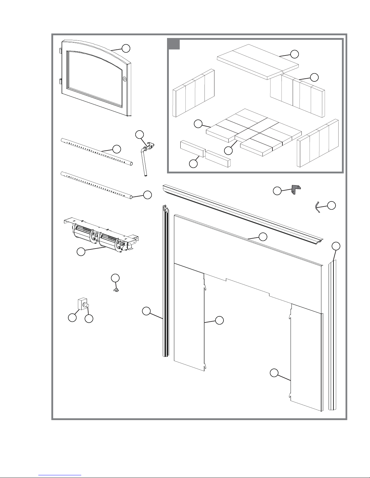
8.0 REPLACEMENTS
Contact your dealer or the factory for questions concerning prices and policies on replacement parts. Normally
all parts can be ordered through your Authorized dealer / distributor.
FOR WARRANTY REPLACEMENT PARTS, A PHOTOCOPY OF THE ORIGINAL INVOICE WILL BE
REQUIRED TO HONOUR THE CLAIM.
When ordering replacement parts always give the following information:
• Model & Serial Number of appliance
• Installation date of appliance
• Part number
• Description of part
• Finish
* IDENTIFIES ITEMS WHICH ARE NOT ILLUSTRATED. FOR
FURTHER INFORMA TION, CONTACT YOUR AUTHORIZED DEALER.
REF NO. 2201 DESCRIPTION
1* W325-0042 SPRING HANDLE - SMALL BLACK
1* W325-0043 SPRING HANDLE - LARGE BLACK
2 W090-0015 BRICK 4.5” X 9”
3 W090-0168 BRICK 4.5” X 6.250”
4 W090-0179 BRICK 2.750” X 9” X 1.250”
5 W090-0172 BRICK 2” X 9” X 1.250”
6 W580-0008 COMPLETE BRICK SET
7 W018-0118 FIBRE BAFFLE
8 W225-0214 BLACK DOOR
9* W010-2325 KIT, REPLACEMENT GLASS & GASKET (INCLUDED GLASS GASKET)
10* W020-0563 KIT, GLASS GASKET
11 W720-0134 REAR SECONDARY AIR TUBE
12 W720-0135 FRONT SECONDARY AIR TUBE
13* W385-0487 TIMBERWOLF LOGO
14 W020-0503 ASSY, DOOR HANDLE
15 W062-0024 BLOWER
16 W660-0019 VARIABLE SPEED SWITCH
17 W690-0002 THERMAL SWITCH
18 W380-0002 KNOB
19 W263-0107 FLASHING, RS
20 W263-0106 FLASHING, TOP
21 W263-0108 FLASHING, LS
22 W715-0687 TRIM, RIGHT SIDE BLACK
23 W715-0685 TRIM, TOP BLACK
24 W715-0686 TRIM, LEFT SIDE BLACK
25 W020-0021 HARDWARE,TRIM (CORNER CLIPS)
26 W160-0014 SPRING CLIP
27* W020-0043 KIT, DOOR GASKET
COMPONENTS
!
WARNING
FAILURE TO POSITION THE PARTS
IN ACCORDANCE WITH THIS
MANUAL OR FAILURE TO USE ONLY
PARTS SPECIFICALLY APPROVED
WITH THIS APPLIANCE MAY
RESULT IN PROPERTY DAMAGE OR
PERSONAL INJURY.
41.1
W415-0890 / A / 04.28.10
Page 27
27
11
8
6
7
4
2
14
3
5
12
25
26
16
15
18
20
22
17
23
19
21
W415-0890 / A / 04.28.10
Page 28

28
9.0 TROUBLE SHOOTING
TURN OFF THE ELECTRICAL POWER BEFORE SERVICING THE APPLIANCE.
APPLIANCE MAY BE HOT, DO NOT SERVICE UNTIL APPLIANCE HAS COOLED.
DO NOT USE ABRASIVE CLEANERS.
WHEN CHECKING CONNECTIONS, INSTALLING JUMPER WIRES (FOR TEST PURPOSES ONLY) OR
REPLACING COMPONENTS, UNPLUG HEATER FROM THE RECEPTACLE TO PREVENT ELECTRICAL
SHOCK OR DAMPAGE TO THE COMPONENT.
PROBLEM SOLUTION
Can’t get the fi re started. - Not enough kindling / paper? Add more.
- Not enough air? Ensure air control is fully open.
- Cold air blockage? Burn a piece of paper to establish a draft.
- Use dry seasoned wood.
- Flue blockage? Inspect chimney.
Smokes when door is
open.
Appliance emits odour. - Paint curing. See “GENERAL INSTRUCTIONS” section.
Stove doesn’t burnt hot
enough.
Wood burns too fast. - Air control may need to be adjusted down.
Dirty glass. - Air control may be closed too far.
Blower does not run. - Appliance may not be up to temperature.
- Cold air blockage? Burn a piece of paper to establish a draft.
- Insuffi cient draft? Add more pipe.
- Let air stabilize before opening door.
- Ensure baffl es are positioned correctly.
- Negative pressure? Open a window near the appliance.
- Wood is too wet.
- Insuffi cient draft? Add more pipe.
- Not enough air? Ensure air control is fully open.
- Check to see ash plug is properly seated (if equipped).
- Check door gasket for adequate seal.
- Wood may be extremely dry.
- Burn hotter, smaller fi res.
- Use well seasoned wood.
- Ensure blower has power.
!
WARNING
42.14A
W415-0890 / A / 04.28.10
Page 29

10.0 WARRANTY
TIMBERWOLF products are manufactured under the strict Standard of the World Recognized
ISO 9001 : 2008 Quality Assurance Certifi cate.
TIMBERWOLF products are designed with superior components and materials, assembled by trained craftsmen
who take great pride in their work. The complete appliance is thoroughly inspected by a qualifi ed technician before
packaging to ensure that you, the customer, receives the quality product that you expect from TIMBERWOLF.
TIMBERWOLF WOOD APPLIANCE PRESIDENT’S LIMITED WARRANTY
The following materials and workmanship in your new TIMBERWOLF appliance are warranted against defects as
defi ned below:
The combustion chamber is warranted against defects for a period of 25 years.
The secondary air tubes are warranted against defects for a period of fi ve years.
All other wearable parts and electrical components such as blowers, thermal switches, switches, wiring,
rheostats, fi rebrick, ceramic glass (thermal breakage only), fi bre baffl es and gasketing are covered and Wolf
Steel will provide replacement parts free of charge during the fi rst year of the limited warranty.
Any labour related to warranty repair is not covered.
* Construction of models vary. Warranty applies only to components included with your specifi c heater.
29
CONDITIONS AND LIMITATIONS
Wolf Steel warrants its TIMBERWOLF products against manufacturing defects to the original purchaser only. Registering your warranty is not
necessary. Simply provide your proof of purchase along with the model and serial number to make a warranty claim. Provided that the purchase
was made through an authorized TIMBERWOLF dealer your appliance is subject to the following conditions and limitations:
This factory warranty is non-transferable and may not be extended whatsoever by any of our representatives.
The appliance must be installed by an authorized service technician or contractor. Installation must be done in accordance with the installation
instructions included with the product and all local and national building and fi re codes.
This limited warranty does not cover damages caused by misuse, lack of maintenance, accident, alterations, abuse or neglect. Operating the
appliance on high for extended periods of time, is neglect. Parts installed from other manufacturers will nullify this warranty.
This limited warranty further does not cover any scratches, dents, corrosion or discoloring caused by excessive heat, abrasive and chemical
cleaners nor chipping on porcelain enamel parts, nor any venting components used in the installation of the appliance.
In the fi rst year only, this warranty extends to the repair or replacement of warranted parts which are defective in material or workmanship
provided that the product has been operated in accordance with the operation instructions and under normal conditions.
After the fi rst year, with respect to the TIMBERWOLF’S President’s Limited Warranty, Wolf Steel may, at its discretion, fully discharge all
obligations with respect to this warranty by refunding to the original warranted purchaser the wholesale price of any warranted but defective
parts.
After the fi rst year, Wolf Steel Ltd. will not be responsible for installation, labour or any other costs or expenses related to the reinstallation of a
warranted part, and such expenses are not covered by this warranty.
Notwithstanding any provisions contained in the TIMBERWOLF’S President’s Limited Warranty, Wolf Steel’s responsibility under this warranty is
defi ned as above and it shall not in any event extend to any incidental, consequential or indirect damages.
This warranty defi nes the obligations and liability of Wolf Steel with respect to the TIMBERWOLF appliance and any other warranties expressed
or implied with respect to this product, its components or accessories are excluded.
Wolf Steel neither assumes, nor authorizes any third party to assume, on its behalf, any other liabilities with respect to the sale of this product.
Wolf Steel will not be responsible for: over-fi ring, downdrafts, spillage caused by environmental conditions such as rooftops, buildings, nearby
trees, hills, mountains, inadequate vents or ventilation, excessive venting confi gurations, insuffi cient makeup air, or negative air pressures
which may or may not be caused by mechanical systems such as exhaust blowers, furnaces, clothes dryers, etc.
Any damages to appliance, combustion chamber, heat exchanger or other components due to water, weather damage, long periods of
dampness, condensation, damaging chemicals or cleaners will not be the responsibility of Wolf Steel.
Regular cleaning of the fi ne ash generated during the operation of this appliance is a necessary part of maintaining your appliance. Failure of
any components, which is attributed to poor maintenance, is not warrantable and will not be covered by this policy.
Wolf Steel reserves the right to have its representative inspect any TIMBERWOLF product or part thereof prior to honouring any warranty claim.
ALL SPECIFICA TIONS AND DESIGNS ARE SUBJECT TO CHANGE WITHOUT PRIOR NOTICE DUE TO ON-GOING PRODUCT IMPROVEMENTS.
2.11_A
W415-0890 / A / 04.28.10
Page 30
30
11.0 SERVICE HISTORY
W415-0890 / A / 04.28.10
43.1
Page 31

12.0 NOTES
31
44.1
W415-0890 / A / 04.28.10
Page 32

32
W415-0890 / A / 04.28.10
44.1
 Loading...