

Page 1

OWNER’S MANUAL
MODE D’EMPLOI
BEDIENUNGSANLEITUNG
GEBRUIKSAANWIJZING
MANUAL DEL PROPIETARIO
MANUALE D’ISTRUZIONI
Page 2

DE 31-45
FR 16-30
GB 01-15
NL 46-60
ES 61-75
IT 76-90
HEDGE TRIMMER
TAILLE HAIE
HECKENSCHERE
DECESPUGLIATORE
CORTASETOS
HEGGENSCHAAR
Page 3

12. Limited warranty ............................................ 15
7.
Operation
......................................................
9
4.
Symbols on the machine ................................ 3
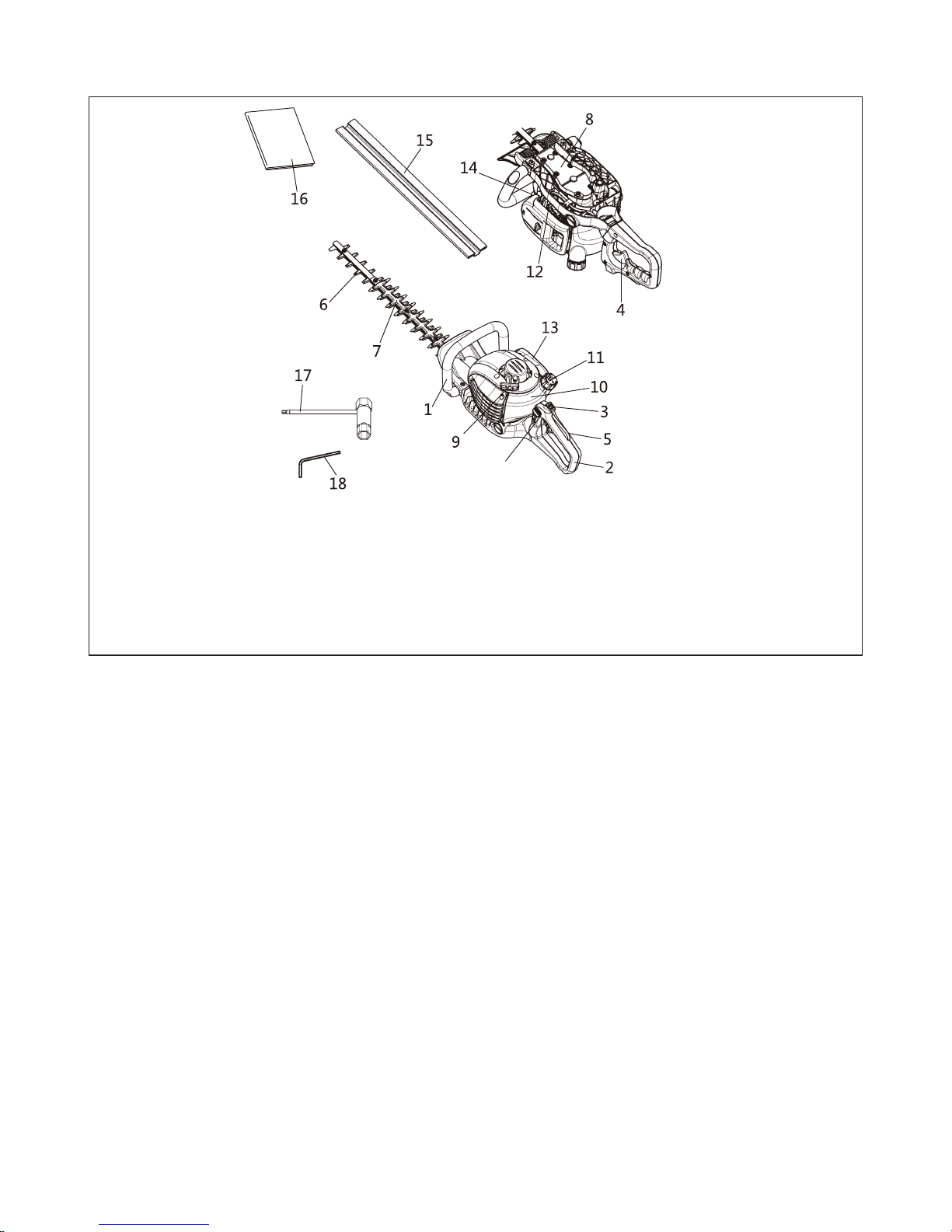
1. Parts location ...................................................2
SAFETY FIRST
Instructions contained in war
nings within this manual marked
with a
symbol concern cr
itical points which must be taken
into consideration to prevent possible serious bodily injury, and
for this reason you are requested to read all such instructions
carefully and follow them without fail.
WARNINGS IN THE MANUAL
WARNING
This mark indicates instructions, which must be followed in order to prevent accidents, which could lead to serious bodily injury or death.
IMPORTANT
This mark indicates instructions, which must be followed, or it
leads to mechanical failure, breakdown, or damage.
NOTE
This mark indicates hints or directions useful in the use of the
product.
Contents
2. Specifications .................................................
2
3. Warning labels on the machine ...................... 3
5. For safe operation........................................... 4
6. Fuel ................................................................. 7
8. Maintenance ................................................. 11
9. Storage ......................................................... 14
10. Disposal ........................................................ 14
11. Troubleshooting guide .................................. 14
GB 1
Page 4
Dry weight............................................................................................................6,0 kg
Spark plug ............................................................................................... LD BM6A
Model
.............................................................................................................1E34F
Blade length (from the tip of Gear Case)...........................................................600 mm
Model ..................................................................................................................HT260
19.
Loc
king le
v
er
1. Parts location
1.Front handle
2.
Rear handle
3.
Stop switch
4. Throttle trigger
5. Safety lock
6. Blades
7. Blade guard
T
ype
................................................................................................ double-action type
Engine
Displacement ...........................................................................................
25.4 cm
3
Carburetor ....................................................................................
Diaphragm type
Ignition system ..................................................... I.C.controlled flywheel magneto
Fuel ............................................................................. mixture (Gasoline 40 : Oil 1)
Fuel tank capacity ................................................................................................. 0,6 L
Starter ...................................................................................................... Recoil starter
Clutch .................................................................................................. Centrifugal type
Specifications are subject to change without notice.
2. Specification
8.
Gear case
9.
Star
ter knob
10.
Fuel tank
11. Fuel cap
12. Choke lever
13. Air cleaner cover
14. Spark plug cap
15. Blade cover
16. Operator’s manual
17. Socket
18. Allen key
19
GB 2
Page 5
G
B
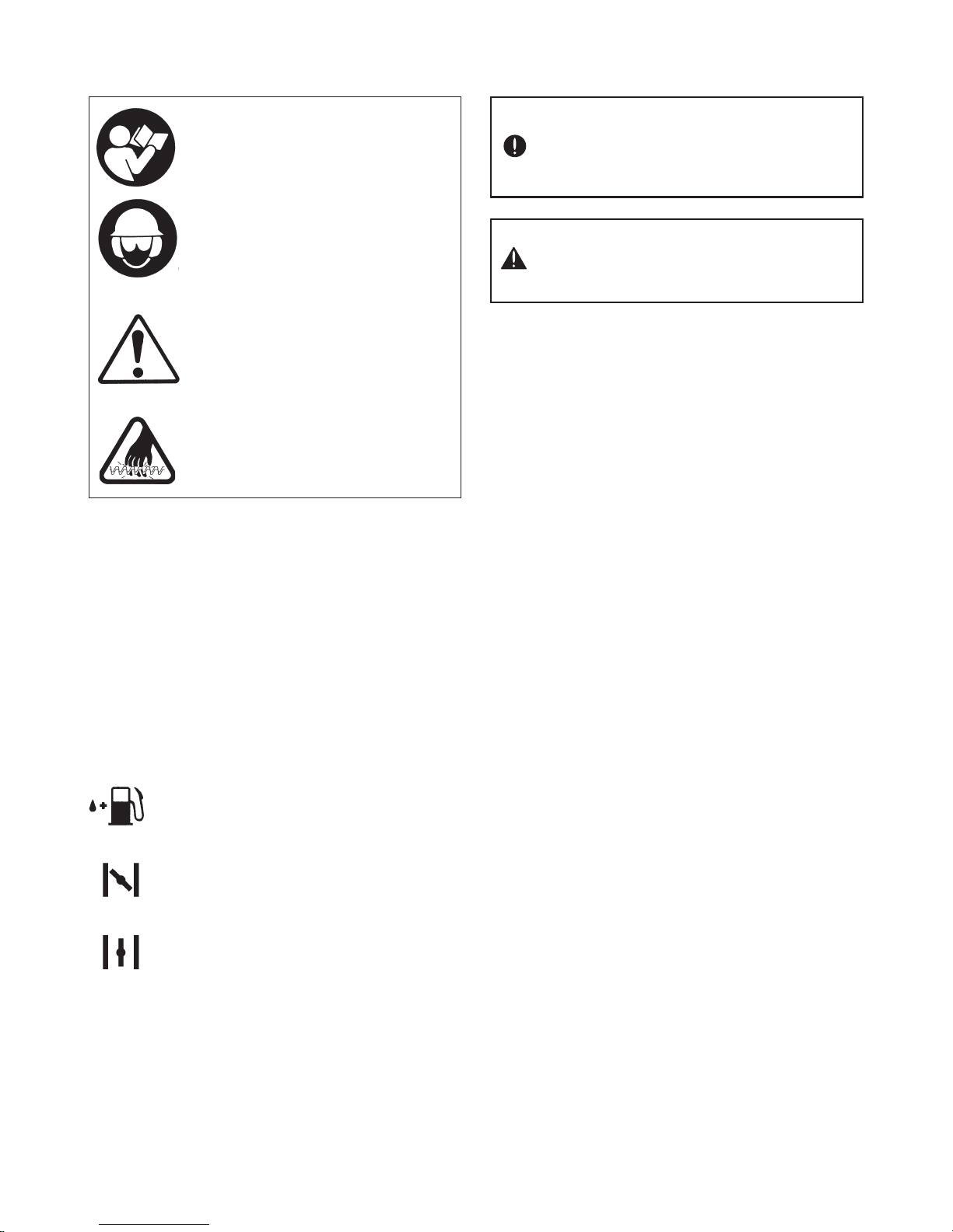
3. Warning labels on the machine
If war
ning label peels off or becomes soiled and
impossible to r
ead, you should contact the
dealer from which you purchased the product
to order new labels and affix them in the required
location(s).
Never modify your machine.
We won’t warrant the machine, if you use the
remodeled hedge trimmer or if you don’t observe the proper usag
e written in the manual.
(1)
(1)Read o
wner's man
ual before operat-
ing this machine.
(2)Wear head, ey
e and ear protection.
(3)Handling this machine improperly
could result in accidents causing serious injury or death. Read this
manual carefully and practice using
the hedge-trimmer until you are fully
acquainted with all operations and
have learned to use it correctly.
(4)This is extremely sharp and can eas-
ily cause cuts.
4. Symbols on the machine
For safe operation and maintenance, symbols are carved in relief on the machine. Accor
ding to these indications,
please be careful not to make a mistake.
The port to refuel the “MIX GASOLINE”
Position: FUEL TANK CAP
The direction to close the choke
Position: AIR CLEANER COVER
The direction to open the choke
Position: AIR CLEANER COVER
GB 3
Page 6
gases contain dangerous carbon
monoxide.
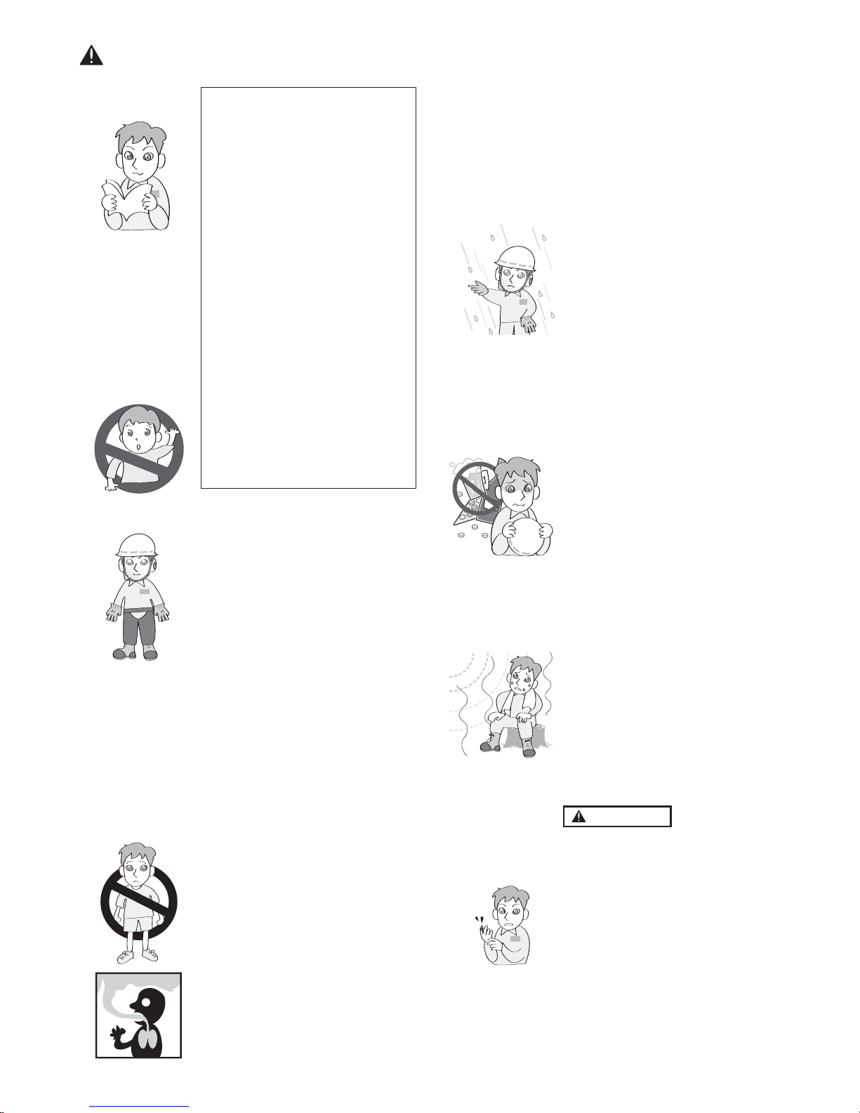
2. Never use the pr
oduct,
a. when the ground is slippery
or when you can’t maintain a
steady posture.
b. At night, at times of heavy fog,
or at any other times when
your field of vision might be
limited and it would be difficult to gain a clear view of the
working area.
c. During rain, during storms at
times of strong or gale-force
winds, or at any other times
when weather conditions
might make it unsafe to use
the product.
WORKING PLAN
1. You should never use the product when under the influence of
alcohol, when suffering from exhaustion or lack of sleep, when
suffering from drowsiness as a result of having taken cold medicine
or at any other time when a possibility exists that your judgment
might be impaired or that you
might not be able to operate the
product properly and in a safe
manner.
2. When planning your work schedule, allow plenty of time to rest.
Limit the amount of time over
which the product is to be used
continuously to somewhere
around 30 ~ 40 minutes per session, and take 10 ~ 20 minutes of
rest between work sessions. Also
try to keep the total amount of
work performed in a single day
under 2 hours or less.
WARNING
1
. If you don’t observe the working
time, or working manner (See
“USING THE PRODUCT”), Repetitive Stress Injury (RSI) could
occur.
If you feel discomfort, redness and
swelling of your fingers or any
other part of your body, see a doctor before getting worse.
2. To avoid noise complaints, in general, operate product between
8 a.m. and 5 p.m. on weekdays
and 9 a.m. to 5 p.m. on weekends.
1
.
THIS MACHINE CAN CAUSE
SERIOUS INJURIES. Read this
manual carefully until you completely understand and follow all
safety and operating instructions. Also, know how to stop the
machine quickly in an emergency.
2. Keep this manual handy so that
you may refer to it later whenever any questions arise. Also
note, if you have any questions
which cannot be answered
herein, contact the dealer from
whom you purchased the product.
3. Always be sure to include this
manual when selling, lending, or
otherwise transferring the ownership of this product.
4. Never allow children or anyone
unable to fully understand the
directions given in the manual
to use the machine.
WORKING CONDITION
1. When using the product, you
should wear proper clothing and
protective equipment.
(1) Helmet
(2) Ear protectors
(3) Protection goggles or face
protector
(4) Thick work gloves
(5) Non-slip-sole work boots
2. And you should carry with you.
(1) Attached tools
(2) Properly reserved fuel
(3) Spare blade
(4) Things to notify your working
area (rope, warning signs)
(5) Whistle (for collaboration or
emergency)
(6) Hatchet or saw (for removal of
obstacles)
(7) First-aid kit
3. Do not wear loose clothing, jewelry, short trousers, sandals, or go
barefoot. Do not wear anything
which might be caught by a moving part of the unit. Secure hair
so it is above shoulder length.
WORKING CIRCUMSTANCE
1. Never start the engine inside a
closed room or building. Exhaust
5. For safe operation
GB 4
Page 7
G
B
BEFORE STARTING
THE ENGINE
1
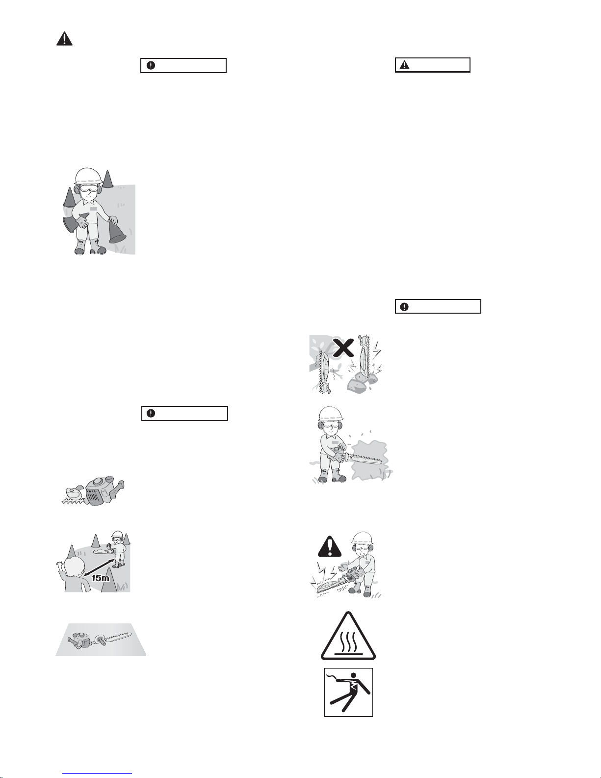
. The area within a perimeter of
15 m of the person using the
product should be considered a
hazardous area into which no one
should enter. If necessary, yellow
warning rope, warning signs
should be placed around the perimeter of the area. When work is
to be performed simultaneously
by two or more persons, care
should also be taken to constantly
look around or otherwise check
for the presence and locations of
other people working so as to
maintain a distance between
each person sufficient to ensure
safety.
2. Check the condition of working
area to avoid any accident by hitting hidden obstacles such as
stumps, stones, cans, or broken
glass.
IMPOR
TANT
Remo
ve any obstacle before begin-
ning work.
3. Inspect the entire unit for loose
fasteners and fuel leakage. Make
sure that the cutting attachment
is properly installed and securely
fastened.
STARTING THE ENGINE
1. Keep bystanders, especially children, and animals at least 15 m
away from the operating point. If
you are approached, immediately
stop the engine.
2. The product is equipped with a
centrifugal clutch mechanism, so
the cutting attachment begins to
move as soon as the engine is
started by putting the throttle into
the start position. When starting
the engine, place the product
onto the ground in a flat clear area
and hold it firmly in place so as to
ensure that neither the cutting
part nor the throttle come into
contact with any obstacle when
the engine starts.
IMPOR
TANT
Check and follow the local regulations as to sound level and hours of
operations for the pr
oduct.
WARNING
• Ne
ver place the throttle into the
high-speed position when starting the engine.
• Never start the engine at the cutting attachment side.
3. After starting the engine, check
to make sure that the cutting attachment stops moving when the
throttle is moved fully back to its
original position. If it continues to
move even after the throttle has
been moved fully back, turn off
the engine and take the unit to
your authorized Timberpro servicing dealer for repair.
USING THE PRODUCT
IMPOR
TANT
Cut only materials recommended b
y
the manufacturer. And use only for
tasks explained in the manual.
1. Grip the handles firmly with both
hands using your whole hand.
Place your feet slightly apart
(slightly further apart than the
width of your shoulders) so that
your weight is distributed evenly
across both legs, and always be
sure to maintain a steady, even
posture while working.
2. Maintain the speed of the engine
at the level required to perform
cutting work, and never raise the
speed of the engine above the
level necessary.
3. If the unit starts to shake or vi-
brate, turn off the engine and
check the whole unit. Do not use
it until the trouble has been properly corrected.
4. Keep all parts of your body away
from moving cutting attachment
and hot surfaces.
5.
Never touch the muffler, spark plug,
or other metallic par
ts of the engine
while the engine is in operation or
immediately after shutting down the
engine. Doing so could result in
serious burns or electrical shock.
6. While operating the machine be
always sure of a safe and secure
operating position especially
when using steps or a ladder
.
5. For safe operation
GB 5
Page 8
servicing dealer for`
authori-
from the store near
est
is desi-
The engine of the product
• IF SOMEONE COMES
1. Guard against hazardous situations at all times. Warn adults to
keep pets and children away from
the area. Be careful if you are approached. Injury may result from
flying debris.
2. If someone calls out or otherwise
interrupts you while working, always be sure to turn off the engine before turning around.
MAINTENANCE
1. In order to maintain your product
in proper working order, perform
the maintenance and checking
operations described in the
manual at regular intervals.
2. Always be sure to turn off the engine and disconnect the spark
plug wire before performing any
maintenance, checking procedures or working on the machine.
W
ARNING
The metallic par
ts reach high temperatures immediately after stopping the engine.
3. In the event that any part must be
replaced or any maintenance or
repair work not described in this
manual must be performed,
please contact a representative
assistance.
4. Under no circumstances should
you ever take apart the product
or alter it in any way. Doing so
5. For safe operation
might result in the product becoming damaged during operation or the pr
oduct becoming un-
able to operate properly.
HANDLING FUEL
1.
uct is designed to run on a mixed
fuel, which contains highly flammable gasoline. Never store cans
of fuel or refill the tank of the unit
in any place where there is a
boiler, stove, wood fire, electrical
sparks, welding sparks, or any
other source of heat or fire which
might ignite the fuel.
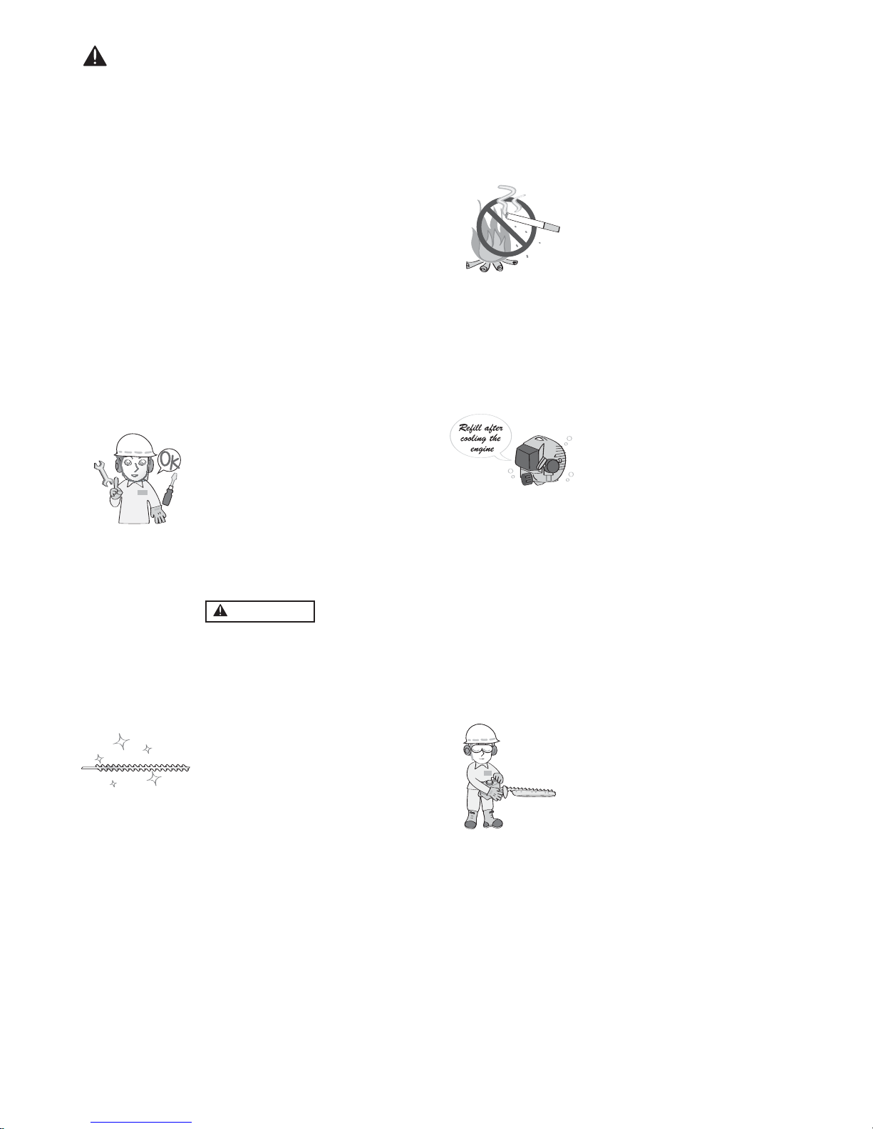
2. Never smoke while operating the
unit or refilling its fuel tank.
3. When refilling the tank, always
turn off the engine and allow it to
cool down. Take a careful look
around to make sure that there are
no sparks or open flames anywhere nearby before refueling.
4. Wipe spilled fuel completely using a dry rag if any fuel spillage
occurs during refueling.
5. After refueling, screw the fuel cap
back tightly onto the fuel tank and
then carry the unit to a spot 3 m
or more away from where it was
refueled before turning on the
engine.
6. Do not inhale fuel fumes as they
are toxic.
TRANSPORTATION
1. When hand-carrying the product,
cover over the cutting part if necessary, lift up the product and
carry it paying attention to the
blade.
2. Never transport the product over
rough roads over long distances
by vehicle without removing all
fuel from the fuel tank. If doing so,
fuel might leak from the tank during transport.
7. Check the cutting attachment.
Never use blades that are dull,
cracked or damaged.
8. To reduce the fire hazard, clean
dirt, leaves and surplus lubricant,
etc from the muffler and engine.
GB 6
Page 9
6. Fuel
GB 7
■ FUEL
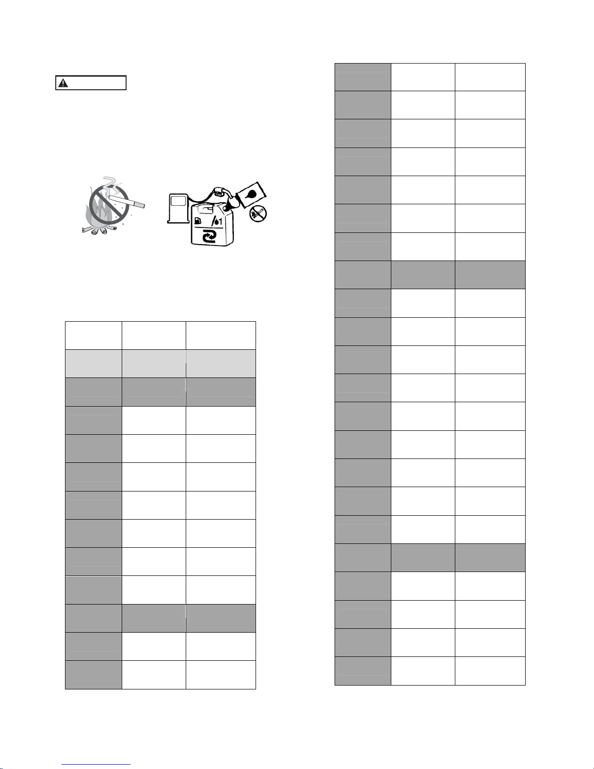
WARNING
• Gasoline is ver
y flammable. Avoid smoking or
bringing any flame or sparks near fuel. Make sure
to stop the engine and allow it cool before refueling the unit. Select outdoor bare ground for fueling
and move at least 3 m (10 ft) away from the fueling
point before starting the engine.
40
- ONLY USE UNLEADED 95 FUEL (STANDARD) AND
SYNTHETIC 2-STROKE OIL FOR THE MIXTURE.
MIX 25:1 40:1
Gasoline Oil in ml Oil in ml
1,0 Liter 40 25
1,5 Liter 60 38
2,0 Liter 80 50
2,5 Liter 100 63
3,0 Liter 120 75
3,5 Liter 140 88
4,0 Liter 160 100
4,5 Liter 180 113
5,0 Liter 200 125
5,5 Liter 220 138
6,0 Liter 240 150
6,5 Liter 260 163
7,0 Liter 280 175
7,5 Liter 300 188
8,0 Liter 320 200
8,5 Liter 340 213
9,0 Liter 360 225
9,5 Liter 380 238
10,0 Liter 400 250
10,5 Liter 420 263
11,0 Liter 440 275
11,5 Liter 460 288
12,0 Liter 480 300
12,5 Liter 500 313
13,0 Liter 520 325
13,5 Liter 540 338
14,0 Liter 560 350
14,5 Liter 580 363
15,0 Liter 600 375
15,5 Liter 620 388
16,0 Liter 640 400
16,5 Liter 660 413
17,0 Liter 680 425
■ RECOMMENDED MIXING RA
TIO
GASOLINE 40 : OIL 1
√
■ FUEL
WARNING
• Gasoline is ver
y flammable. Avoid smoking or
bringing any flame or sparks near fuel. Make sure
to stop the engine and allow it cool before refueling the unit. Select outdoor bare ground for fueling
and move at least 3 m (10 ft) away from the fueling
point before starting the engine.
40
- ONLY USE UNLEADED 95 FUEL (STANDARD) AND
SYNTHETIC 2-STROKE OIL FOR THE MIXTURE.
MIX 25:1 40:1
Gasoline Oil in ml Oil in ml
1,0 Liter 40 25
1,5 Liter 60 38
2,0 Liter 80 50
2,5 Liter 100 63
3,0 Liter 120 75
3,5 Liter 140 88
4,0 Liter 160 100
4,5 Liter 180 113
5,0 Liter 200 125
5,5 Liter 220 138
6,0 Liter 240 150
6,5 Liter 260 163
7,0 Liter 280 175
7,5 Liter 300 188
8,0 Liter 320 200
8,5 Liter 340 213
9,0 Liter 360 225
9,5 Liter 380 238
10,0 Liter 400 250
10,5 Liter 420 263
11,0 Liter 440 275
11,5 Liter 460 288
12,0 Liter 480 300
12,5 Liter 500 313
13,0 Liter 520 325
13,5 Liter 540 338
14,0 Liter 560 350
14,5 Liter 580 363
15,0 Liter 600 375
15,5 Liter 620 388
16,0 Liter 640 400
16,5 Liter 660 413
17,0 Liter 680 425
■ RECOMMENDED MIXING RA
TIO
GASOLINE 40 : OIL 1
√
Page 10

GB 8
6. Fuel
3. DO NOT USE READY-TO-USE ALKYLATE PETROL, THESE
2. DO NOT USE FUEL TYPE SP95-E10 (10% ETHANOL) TO
• Exhaust emission are controlled by the fundamental engine parameters and components (eq.,
carburation, ignition timing and port timing) without addition of any major hardware or the introduction of an inert material during combustion.
• These engines are certified to operate on unleaded
gasoline.
• If you use a gasoline of a lower octane value than prescribed, there is a danger that the engine temperature may rise and an engine problem such as piston
seizing may consequently occur.
• Unleaded gasoline is recommended to reduce the
contamination of the air for the sake of your health and
the environment.
• Poor quality gasolines or oils may damage sealing
rings, fuel lines or fuel tank of the engine.
■ HOW TO MIX FUEL
WARNING
• Pay attention to a
gitation.
1. Measure out the quantities of gasoline and oil to be
mixed.
2. Put some of the gasoline into a clean, approved fuel
container.
3. Pour in all of the oil and agitate well.
4. Pour in the r
est of gasoline and agitate again for at
least one minute. As some oils may be difficult to
agitate depending on oil ingredients, sufficient agitation is necessary for the engine to last long. Be
careful that, if the agitation is insufficient, there is an
increased danger of early piston seizing due to abnormally lean mixture.
5.
Put a clear indication on the outside of the container
to avoid mixing up with gasoline or other containers.
6. Indicate the contents on outside of container for easy
identification.
■ FUELING THE
UNIT
1. Untwist and remove the fuel cap. Rest the cap on a
dustless place.
2. Put fuel into the fuel tank to 80% of the full capacity.
3. Fasten the fuel cap securely and wipe up any fuel
spillage around the unit.
WARNING
1.
Select flat and bare ground for fueling.
2. Move at least 10 feet (3 meters) away from the fueling point before starting the engine.
3. Stop the engine before refueling the unit. At that
time, be sure to sufficiently agitate the mixed gasoline in the container.
■ FOR YOUR ENGINE LIFE, AVOID:
1.
FUEL WITH NO OIL (RAW GASOLINE) – It will cause
severe damage to the internal engine parts very quickly.
4. OIL FOR 4-CYCLE ENGINE USE – It can cause spark
plug fouling, exhaust port blocking, or piston ring sticking.
5. Mixed fuels which have been left unused for a pe-
riod of one month or more may clog the carburetor
and result in the engine failing to operate properly.
6. In the case of storing the product for a long period of
time, clean the fuel tank after rendering it empty. Next,
activate the engine and empty the carburetor of the
composite fuel.
7. In the case of scrapping the used mixed oil container,
scrap it only at an authorized repository site.
17,5 Liter 700 438
18,0 Liter 720 450
18,5 Liter 740 463
19,0 Liter 760 475
19,5 Liter 780 488
20,0 Liter 800 500
MAKE THE 2-STROKE MIXTURE.
TYPES OF FUELS ARE DIFFERENT IN COMPOSITION AND
NOT COMPATIBLE WITH OUR MACHINES AND CAN RESULT
IN EARLY DAMAGE OF THE ENGINE AND / OR CARBURETOR.
NOTE
As for details of quality assurance, read the description
in the section Limited W
arranty carefully. Moreover, normal wear and change in product with no functional influence are not covered by the warranty. Also, be careful that, if the usage in the instruction manual is not observed as to the mixed gasoline, etc. described therein,
it may not be covered by the warranty.
Page 11
STARTING ENGINE
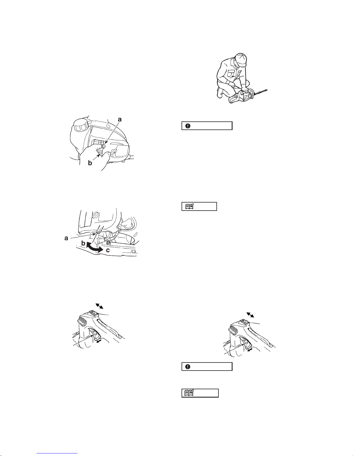
1
. Feed fuel into the fuel tank and tighten the cap se-
curely.
2. Rest the unit on a flat, firm place. Keep the cutting
head off the ground and clear of surrounding objects
as it will start moving upon starting of the engine.
3. Push the primer several times until overflown fuel flows
out in the clear tube.
(a) Primer (b) Clear tube
4.
When the engine is cool, move the choke lever to the
closed position.
(a) Choke lev
er (b) Open (c) Close
5. Set the ignition switch to the “RUN” position.
Release the throttle trigger and make sur
e it is fully back.
6. While holding the unit firmly, pull out the starter rope
quickly until engine fires.
IMPOR
TANT
• A
void pulling the rope to its end or returning it by releasing the knob. Such actions can cause starter failures.
7. Move the choke lever downward to open the choke.
and restart engine.
8. Allow the engine to warm up for a several minutes
before starting opertion.
NOTE
1.
When restarting the engine immediately after stopping it, leave the choke open.
2. Overchoking can make the engine hard to start due
to excess fuel. When the engine failed to start after
several attempts, open the choke and repeat pulling
the rope, or remove the spark plug and dry it.
STOPPING ENGINE
1. Release the throttle trigger and run the engine for half
a minute.
2. Shift the stop switch to the “STOP” position.
IMPORTANT
• Except for an emergency, avoid stopping the engine
while pulling the throttle trigger.
NOTE
If the engine won't stop when setting the stop switch to
the stop position, close the choke lever and stop the
engine.
In this case, please repair the machine at your nearest
servicing dealer.
7. Operation
(a) Throttle tr
igger (b) Stop switch (c) RUN (d) STOP
a
b
(c)
d
a
b
(c)
d
GB 9
Page 12
ith the 2-sided blade model HT 260 use an arc-
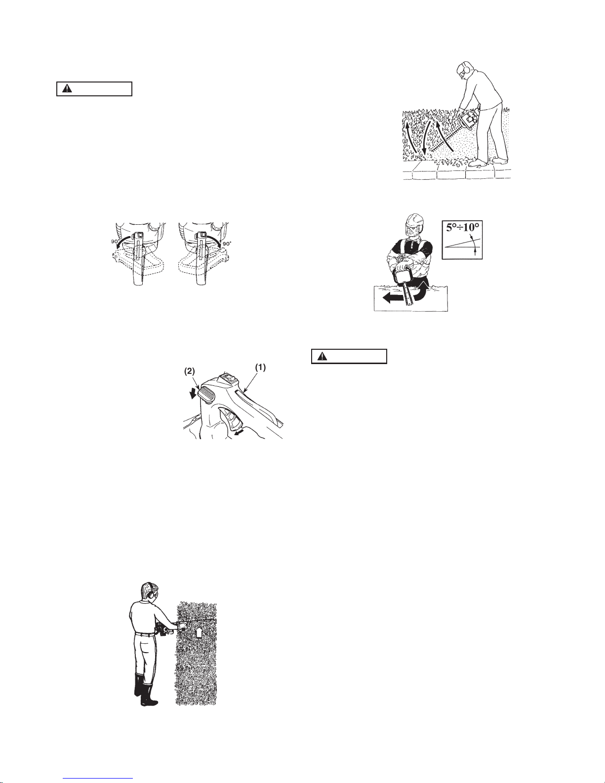
HOW TO USE : HANDLE
CUTTING WORK
WARNING
•
W
eather conditions and altitude may effect
carburation.
•
Do not allow any
one to stay close to the hedgetrimmer while working or while adjusting the carburetor.
•
To
reduce fatigue when trimming hedges, the handle
can be swivelled through 90° to the left or right.
•
Do not press the throttle during this operation!
Proceed as f
ollows:
1. Free the handle by pressing the locking lever.
2. Turn the handle until the locking lever clicks into place.
3. When the handle is locked in its new position, you can
apply the throttle again.
7. Operation
(1) handle
(2) locking lever
•
You can swivel the handle even with the engine
idling because the hedge-trimmer is equipped with
a blade brake that maintains the blades at a
standstill.
■ HEDGE TRIMMING TECHNIQUES
Trim sides of a hedge first, and then the top.
V
ertical cut:
Horizontal cut:
• In or
der to get the best cutting results, slightly tilt the
blade (5÷10°) towards the cutting direction.
Cut slowly, specially with thick hedges.
WARNING
Al
ways f
ollow the safety precautions.
The hedge-trimmer must only be used to trim hedges
or small bushes. It is forbidden to cut other types of
material. Do not use the hedge-trimmer as a lever to
lift, move or break objects, nor lock it on fixed supports. It is forbidden to apply tools or applications
that are not the ones indicated by the manufacturer
onto the hedge-trimmer’s power take-off. Do not use
it for pruning trees or cutting grass.
•W
ing cut from the bottom upwards, then downwar
ds to
use both sides of the blades.
GB 10
Page 13
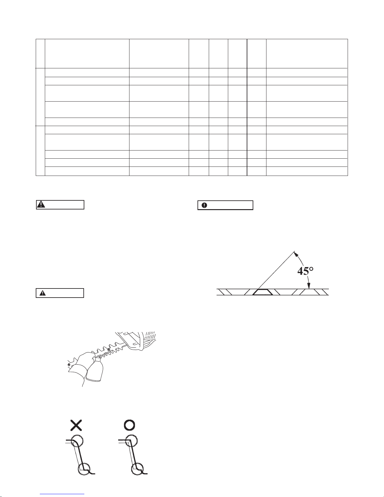
8. Maintenance
Every Ever
y Every
25 50 100
System/components Procedure
Before
hours hours hours
Note
use
after
after
after
fuel leaks, fuel spillage wipe out ✔
fuel tank, air filter, fuel filter inspect/clean ✔✔ r
eplace, if necessary
see adjusting replace carburetor
idle adjusting screw ✔
idling speed if necessary
clean and r
eadjust GAP: 0.6 ~ 0.7 mm
spark plug ✔
plug gap
replace, if necessar
y
intake air cooling vent clean ✔
throttle trigger, stop switch
check operation ✔
clean
take it to a service dealer
cutting parts ✔
if somethings wrong
gear case grease ✔
scr
ews/nuts/bolts tighten/replace ✔✔not adjusting scr
ews
plate receive make sure to attach ✔
ENGINETRIMMER
WARNING
• Make sure that the engine has stopped and is cool
before perf
orming any service to the machine. Contact with moving cutting head or hot muffler may
result in a personal injury.
BLADE
• Clean any resin and plant reside from the blade before and after using the machine.
• Check the cutting edges and reform with a flat file.
WARNING
•
Make sure that the blade bolts are well tightened.
• The blade assembly is designed to automatically
compensate for any play between the blades.
Point :
1. Keep the end corner sharp.
2. Round the root of the edge.
3. Do not use water when using a grinder.
IMPORTANT
When mounting the blade, make sur
e to fasten the
spacer, washer and bolt, then fasten the nut.
■ SHARPENING
Always keep the file or sharpener at an angle of 45° to
the blade, and:
• Always grind in the dir
ection of the cutting edge;
• Note: files cut only in one direction; lift the file from
the blade when returning to start a new pass;
• Remove all burr from the edge of the blade with a slip
stone;
• Remove as little material as possible;
• Before refitting the sharpened blades, remove filings
and then apply grease.
Do not try to sharpen a damaged blade: change it or
take it to a Service dealer.
GB 11
Page 14
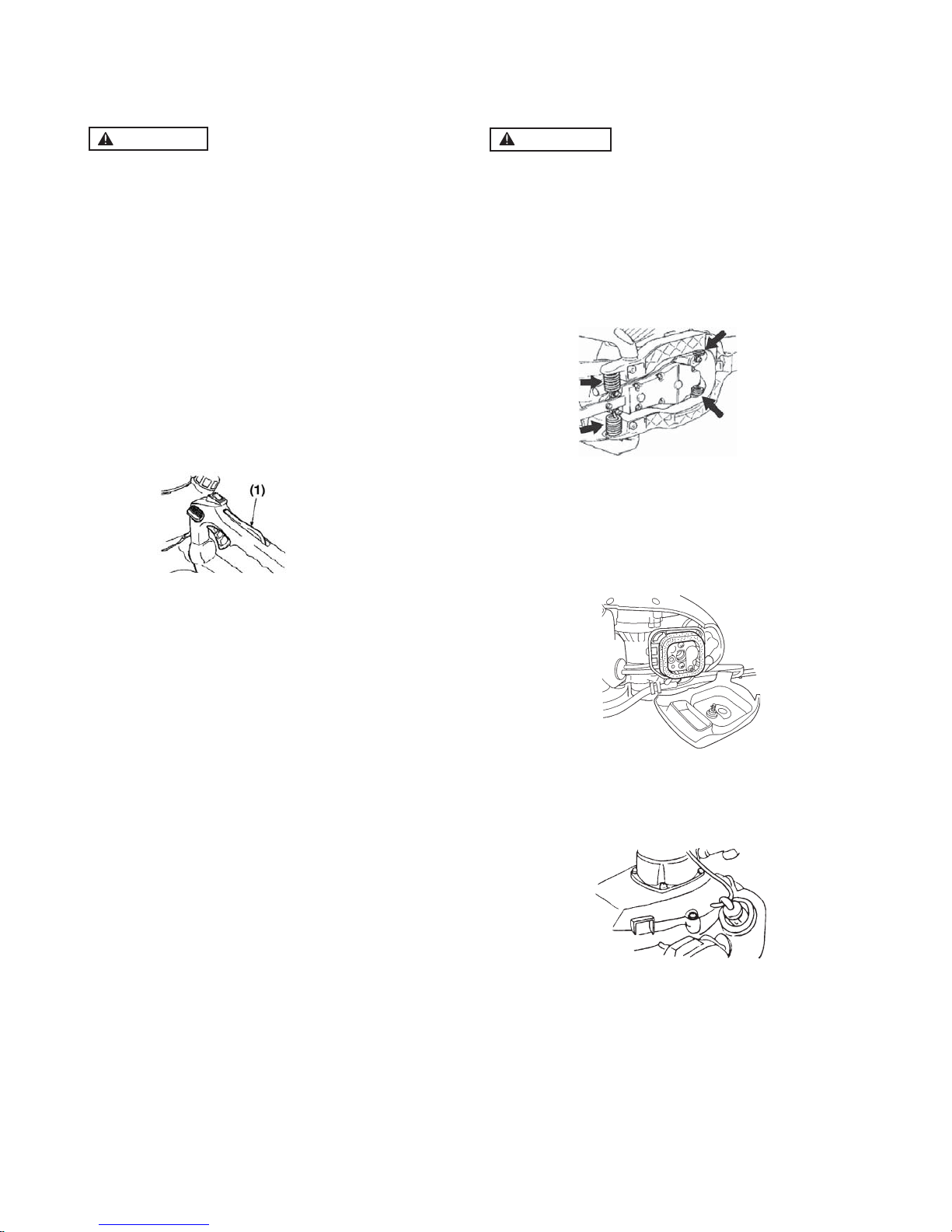
Check periodically if the springs are not
Check periodically if the rubber cushions
G
B
8. Maintenance
ANTI-VIBRATION SYSTEM
WARNING
The defor
med or damaged anti-vibration system may
cause of the breakages like getting rickety or falling
off of engine and/or blade .
•
are not deformed or damaged.
•
deformed or damaged.
AIR FILTER
• The air filter, if clogged, will reduce the engine performance. Check and clean the filter element in warm,
soapy water as required. Dry completely before installing. If the element is broken or shrunk, replace
with a new one.
FUEL FILTER
• When the engine runs short of fuel supply, check the
fuel cap and the fuel filter for blockage.
SAFETY LOCK
WARNING
•
Stop operation when the safety lock is defective.
• Safety lock is the device not to accelerate the throttle
trigger without intention. While pushing the safety lock,
you can accelerate the throttle trigger.
1. Check if the throttle trigger does not move when
you do not push the safety lock.
2. Check if the throttle trigger moves when you grasp
or release it while pushing the safety lock.
3. Check if the safety lock returns to its original po-
sition when you release your hand from safety lock.
• If you find any defects at the checks above, contact
your nearest servicing dealer for repair.
(1) Safety lock
GB 12
Page 15
8. Maintenance
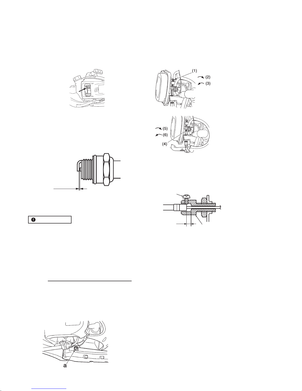
ADJUSTING CARBURETOR
The carburetor has been adjusted at the factory.
Should
your unit need readjustment due to the changes in altitude or operating conditions, please let your skillful dealer
make the adjustment. A wrong adjustment may cause
damage to your unit.
(1) Idle adjusting scr
ew
(2) Up
(3) Down
(4) Fuel adjusting screw
(Opening 1 ± 1/4)
(5) Decr
ease
(6) Increase
WAY OF THE COOLING AIR
• This engine is air-cooled. Dust clogging between the
inlet port of the cooling air and cylinder fins will cause
overheating of the engine. Periodically check and
clean the cylinder fins after removing the air cleaner
and the cylinder cover.
0.6~0.7 mm
TIGHTENING TORQ
UE:
14.7–21
.5 N·m
SPARK PLUG
• Star
ting failure and misfiring are often caused by a
fouled spark plug. Clean the spark plug and check
that the plug gap is in the correct range. For a replacement plug, use the correct type.
IMPOR
TANT
• Note that using an
y spark plug other than those designated may result in the engine failing to operate properly or in the engine becoming overheated and damaged.
• To install the spark plug, first turn the plug until it is
finger tight, then tighten it a quarter turn more with a
socket wrench.
GEAR CASE
• Supply multi-purpose grease at every 50 hours of use.
1. Use a grease pump.
2. Feed grease until it comes out of the base of blades.
(a) Grease nipple: A type
ADJUSTING THROTTLE CABLE
•
The nor
mal play is 1 or 2 mm when measured at the
carburetor side end. Readjust with the cable adjuster
as required and tighten the screw up.
(1)
(3)
(2)
(1) Cable adjuster
(2) 0.04in (1~2mm)
(3) Screw
GB 13
Page 16

When your unit seems to need fur
ther ser
vice, please consult with our ser
vice shop in your ar
ea.
G
B
9. Storage
1. Oil the blade to prevent rust.
2.
Empty the fuel tank and put the cap back on.
3. Remove the spark plug, pour a small amount of oil
into the cylinder.
4. Rotate the crankshaft several times using the starting rope in order to distribute the oil. Put the spark
plug back in.
5. Wrap the engine with a plastic sheet.
6. Store the trimmer indoors in a dry place, dust free
place, out of the reach of children, preferably not in
direct contact with the floor and away from heat
sources.
10. Disposal
• When you dispose of the machine, do not disassemble
the machine.
•
When you dispose of the machine fuel oil, be sure to
follow your local regulations.
11. Troubleshooting guide
Case 1. Starting failure
CHECK
PROB
ABLE CAUSES ACTION
fuel tank A incorrect fuel A drain it and use correct fuel
fuel filter A fuel filter is clogged A clean
carbur
etor adjustment screw A out of nor
mal range A adjust to normal range
sparking (no spark) A spark plug is fouled/wet A clean/dry
A plug gap is incorrect A correct (GAP: 0.6 ~ 0.7 mm)
spark plug A disconnected A r
etighten
Case 2. Engine star
ts but does not keep running/hard re-starting
CHECK PROB
ABLE CAUSES ACTION
fuel tank A incorrect fuel or staled fuel A drain it and use correct fuel
carburetor adjustment screw A out of nor
mal range A adjust to normal range
muffler, cylinder (exhaust por
t) A carbon is built-up A consult with the repair specialty store
air cleaner A clogged with dust A wash
cylinder fin, fan cover A clogged with dust A consult with the repair specialty store
GB 14
Page 17

12. Limited warranty
Should any failure occur on the product under normal
operating conditions within the applicable warranty period, the failed part will be replaced or repaired free of
charge by a TIMBERPRO authorized dealer.
WARRANTY PERIOD: 2 years (6 months if used professionally, and 30 days if used for rental purpose) from the
date of initial purchase.
THE PURCHASER SHALL BEAR COSTS OF TRANSPORTING THE UNIT TO / FROM TIMBWERPRO
DEALER.
THE PURCHASER SHALL NOT BE CHARGED FOR DIAGNOSTIC LABOR WHICH LEADS TO THE DETERMINATION THAT A WARRANTED PART IS DEFECTIVE, IF
THE DIAGNOSTIC WORK IS PERFORMED AT THE
DEALER.
THE PURCHASER OR OWNER IS RESPONSIBLE FOR
THE PERFORMANCE OF THE REQUIRED MAINTENANCE AS DEFINED BY THE MANUFACTURER IN THE
OWNER/OPERATOR MANUAL.
ANY WARRANTED PART WHICH IS NOT SCHEDULED
FOR REPLACEMENT AS REQUIRED MAINTENANCE,
OR WHICH IS SCHEDULED ONLY FOR REGULAR INSPECTION TO THE EFFECT OF REPAIR OR “REPLACE
AS NECESSARY” SHALL BE WARRANTED FOR THE
WARRANTY PERIOD. ANY WARRANTED PART WHICH
IS SCHEDULED FOR REPLACEMENT AS REQUIRED
MAINTENANCE SHALL BE WARRANTED FOR THE PERIOD OF TIME UP TO THE FIRST SCHEDULED
REPLACEMENT POINT FOR THE PART.
ANY REPLACEMENT PART THAT IS EQUIVALENT IN
PERFORMANCE AND DULABILITY MAY BE USED IN
NON-WARRANTY MAINTENANCE OR REPAIRS, AND
SHALL NOT REDUCE THE WARRANTY OBLIGATION
OF THE COMPANY.
THE COMPANY IS LIABLE FOR DAMAGES TO OTHER
ENGINE COMPONENTS CAUSED BY THE FAILURE OF
A WARRANTED PART STILL UNDER WARRANTY.
THE WARRANTY DOES NOT APPLY TO THOSE UNITS
WHICH HAVE BEEN DAMAGED BY NEGLIGENCE OF
INSTRUCTION LISTED IN THE OWNER/OPERATOR
MANUAL FOR PROPER USE AND MAINTENANCE OF
THE UNITS ACCIDENT MISHANDLING, ALTERATION,
ABUSE, IMPROPER LUBRICATION, USE OF ANY PARTS
OR ACCESSORIES OTHER THAN THOSE SPECIFIED
BY THE COMPANY, OR OTHER CAUSES BEYOND THE
COMPANY’S CONTROL.
THIS WARRANTY DOES NOT COVER THOSE PARTS
REPLACED BY NORMAL WEAR OR HARMLESS
CHANGES IN THEIR APPEARANCE.
THERE ARE NO OTHER EXPRESS WARRANTIES.
IMPLIED WARRANTIES INCLUDING THOSE OF MER-
CHANTABILITY AND FITNESS FOR A PARTICULAR
PURPOSE ARE LIMITED TO TWO (2) YEARS OF HOME
USE [ONE (1) YEAR FOR ANY OTHER USE] FROM THE
ORIGINAL DELIVERY DATE.
LIABILITIES FOR INCIDENTAL OR CONSEQUENTIAL
DAMAGE UNDER ANY AND ALL WARRANTIES ARE
EXCLUDED.
IF YOU NEED TO OBTAIN MORE INFORMATION,
PLEASE CALL YOUR NEAREST SERVICE CENTER,
OR PLEASE CHECK TIMBERPRO WEB SITE
http://www.techandtrade.com/
IN CASE OF FAILURE THE PREFERENCE IS GIVEN
TO A REPLACEMENT OR REPARATION OF THE FAULTY PART IN THE FIRST PLACE. ONLY THE COMPANY OR AN AUTHORIZED DEALER CAN DECIDE
IF AN ITEM SHOULD BE REPLACED ENTIRELY. THIS IS NOT THE PURCHASER’S CHOICE.
GB 15
Page 18

7102
June
ht19
____________________
EC Declaration of Conformity
We, BVBA Tech and Trade
Paalstraat 29 BE-2223 Schriek (Heist-Op-Den-Berg) - Belgium,
Herewith declare under our sole responsibility that the GASOLINE HEDGE TRIMMER
Model ................................: HT 260
Produced under the registered trademark of
Meets all relevant requirements of the above mentioned directives
2006/42/EC Machinery Directive (MD)
2014/30/EU Electromagnetic Compatibility Directive (EMC)
97/68/EC amended by 2010/26/EC Directive of Emission
2000/14 EC & 2005 /88 EC Directive of EU Noise
Using the following draft and transposed standards
EN ISO 10517:2009
EN ISO 14982:2009
Having been type examined to the requirements of the directives by:
TÜV Rheinland LGA Products GmbH Notified Body number: 0197
Tillystraße 2
Certificate Number: AM 503495602 0001
AE 50344469 000190431 Nürnberg
Country : Germany
Conformity assessment procedure: 2000/14/EC-Appendix V
Measured level of the acoustic output LWA 107,4 dB (A).
Guaranteed level of the acoustic output LWA 110 dB (A).
EC type-approval No.: e11*97/68SA*2010/26*2710*00 ( )(EUII Emission)
etaD dengiS
Ⅱ
 Loading...