

Page 1
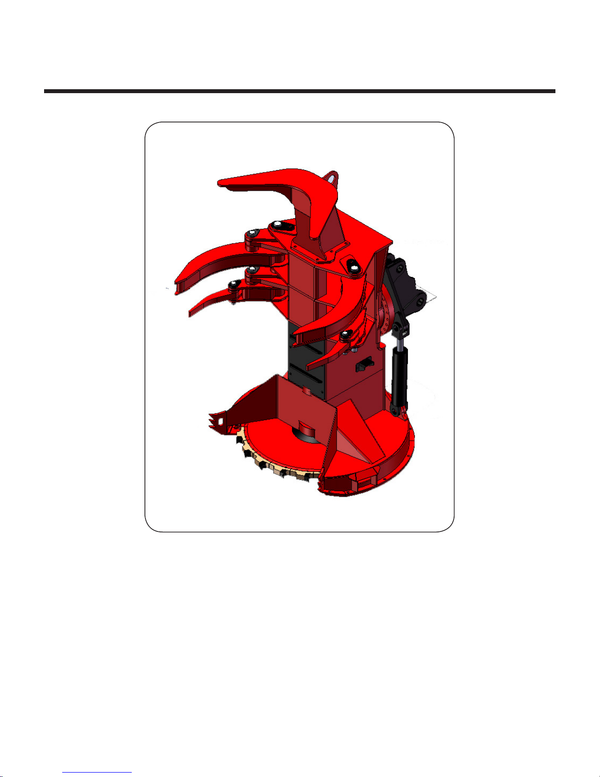
Disc Saw
TimberPro DS-22 Disc Saw
Operation, Maintenance, and Parts
1
Operation, Maintenance, and Parts
Page 2

Introduction ...
Dear Valued Customer,
This catalog contains operating instructions, maintenance instructions and parts information for the
TimberPro 22" Disc Saw attachment, including normally available options. Although great care was
employed during the preparation of this manual to insure the accuracy of illustrations and listings,
TimberPro Inc, cannot be held responsible for errors or substitutions, nor changes made after the
date of issue. This catalog is compiled from information available and current at the time of documentation, TimberPro Inc, reserves the right to improve it’s products without giving prior notice or
incurring obligation.
TimberPro strongly advises that you take this training manual home and study it so that you
have an understanding and working knowledge of your new equipment
Thank You,
Pat Crawford
President
TimberPro, LLC
Operation, Maintenance, and Parts
2
Page 3

Table Of Contents ...
Group 1 - Operator and Maintence Information
General Safety Information . . . . . . . . . . . . . . . . . . . . . . . . . . . . . . . . . . . . . . 5
Service And Maintenance Precautions . . . . . . . . . . . . . . . . . . . . . . . . . . . . . 6
Cutting Attachment Safety . . . . . . . . . . . . . . . . . . . . . . . . . . . . . . . . . . . . . . 8
Disc Saw Maintenance Information . . . . . . . . . . . . . . . . . . . . . . . . . . . . . . . . 9
Group 2 - Operating Instructions
General Disc Saw Operating Instructions . . . . . . . . . . . . . . . . . . . . . . . . . . . 10
Group 3 - Disc Saw Hydraulics
Adjusting the Disc Saw Motor Speed . . . . . . . . . . . . . . . . . . . . . . . . . . . . . . 11
Adjusting the Disc Saw Disc Motor Begin of Stroke . . . . . . . . . . . . . . . . . . . 11
Disc Saw Hydraulics Schematic . . . . . . . . . . . . . . . . . . . . . . . . . . . . . . . . . . 12
Group 4 - Disc Saw Parts
Structural Parts . . . . . . . . . . . . . . . . . . . . . . . . . . . . . . . . . . . . . . . . . . . . . . . DS-1
Hydraulic Components . . . . . . . . . . . . . . . . . . . . . . . . . . . . . . . . . . . . . . . . . DS-2
3
Operation, Maintenance, and Parts
Page 4

Operation, Maintenance, and Parts
4
Page 5
General Safety Information
TimberPro’s policy is to produce products that are
safe and reliable. However, even when using well
engineered equipment, there will always be an
element of risk in heavy equipment operation.
Most accidents involving heavy equipment
operation, maintenance or service result from
failure to follow basic safety rules and precautions.
Study all the safety messages carefully, remember
them and apply them when operating, maintaining
or servicing equipment.
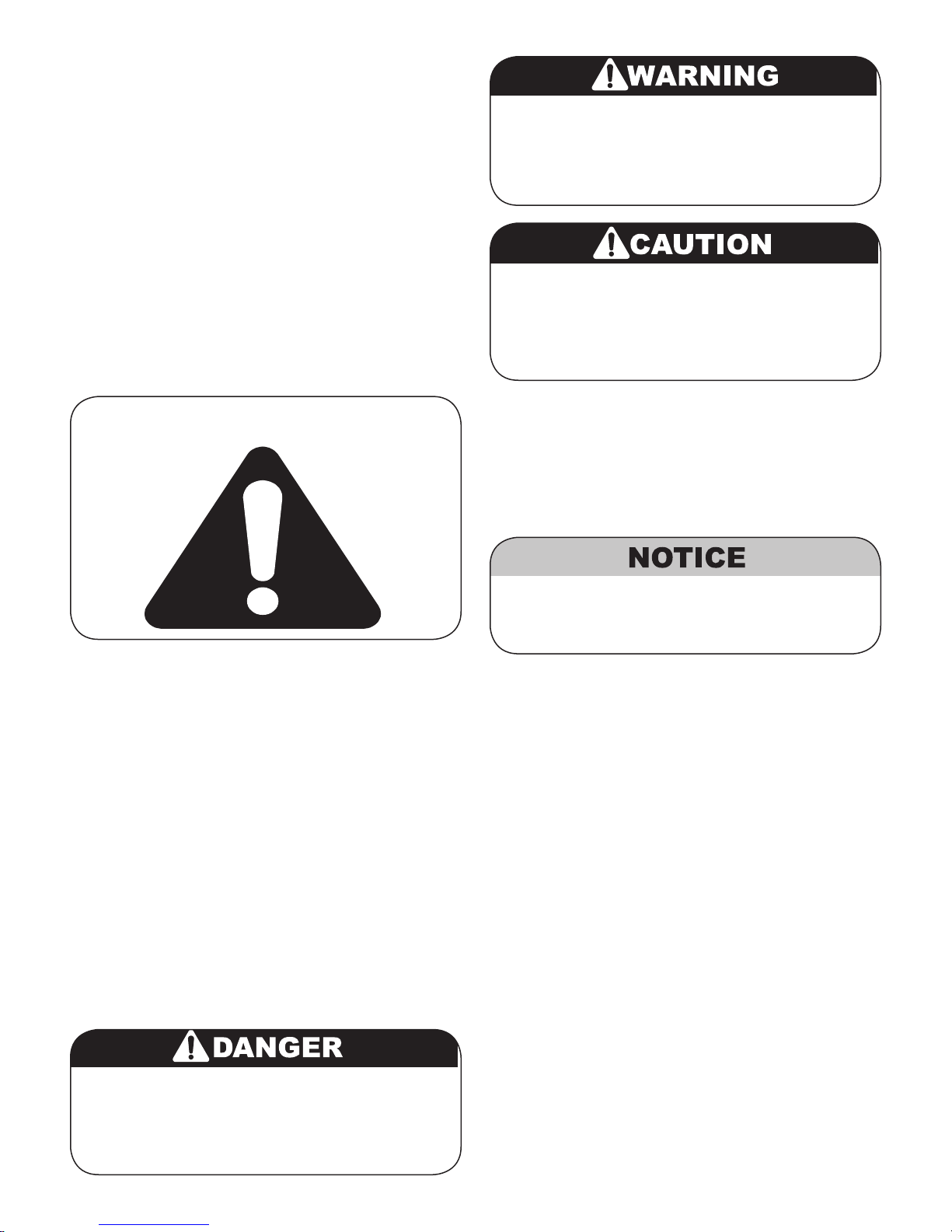
“Safety Alert” Symbol
Identifies that a safety hazard exists. Failure
to follow a WARNING safety message
can result in death or serious personal
injury if proper precautions are not taken.
Identifies that a safety hazard exists. Failure
to follow a CAUTION safety message can
result in personal injury or equipment damage
if the proper precautions are not taken.
The signal words DANGER, WARNING and
CAUTION are used to identify personal safety
hazards and some equipment cautions. The
signal word NOTICE is used to identify
hazards that may damage equipment or its
components.
Figure 1 - Safety Alert Symbol
The “Safety Alert” symbol is used throughout
the manual text and on the machine to
indicate important personal safety measures and
equipment cautions. Carefully read, understand
and follow these instructions to prevent hazardous
situations, possible injuries to personnel or damage
to equipment.
Understanding Signal Words
In this manual and on the safety decals installed
on the machine, the “Safety Alert” symbol is always
accompanied by a signal word to identify the hazard level. Understand the signal words DANGER,
WARNING, and CAUTION.
Identifies the most serious safety hazards.
Failure to follow a DANGER safety message
would result in high probability of death or
serious personal injury.
Follow procedures as outlined to avoid damage
to equipment or its components as a result of
misuse or improper procedures.
The Careful Operator
A careful operator studies, remembers and applies
the basic safety rules and all safety messages found
in the manuals and on the equipment being operated, maintained or serviced. This person also has
the required training, skills and tools to operate the
equipment and/or perform the required maintenance
and service procedures.
TimberPro cannot anticipate every possible
circumstance where a potential hazard may exist.
Therefore, the safety messages and equipment
cautions found in the manuals and on the
machine are not all inclusive. If an operating
technique, maintenance or service procedure, tool,
etc... not specifically recommended by TimberPro is
used, it is your responsibility to insure it is safe for
yourself and others. You should also be sure the
machine will not be damaged or made unsafe by
the operation, maintenance procedures or service
procedures you choose.
WHEN IT COMES TO SAFETY, NOTHING WILL
EVER REPLACE A CAREFUL OPERATOR.
5
Operation, Maintenance, and Parts
Page 6
00007
00008
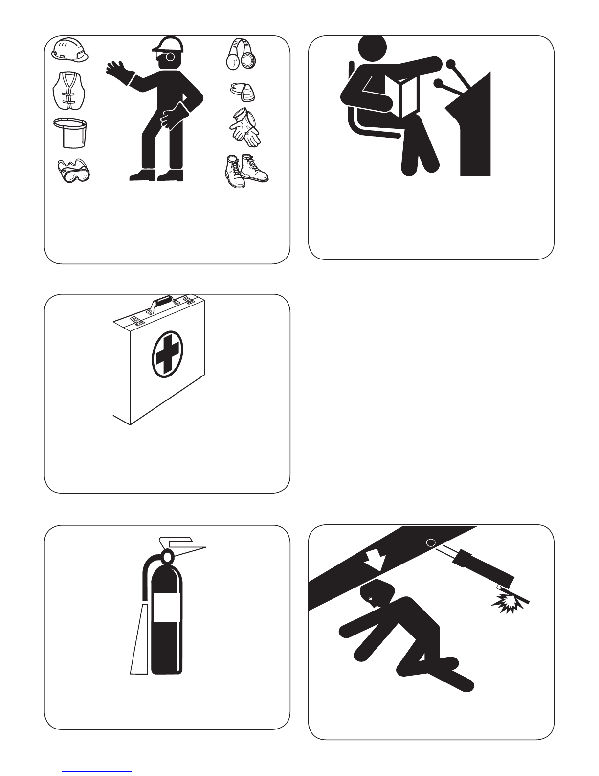
Use recommended protective clothing and safety
devices such as gloves, safety boots, safety hat,
reflective vests and eye, ear and respiratory
protection as required by job conditions.
00010
Keep a comprehensive and complete first aid kit
in an easily accessible place on the machine at
all times.
Comply with the instructions in this manual and
your company’s regulations for the operation of
this machine.
YOU MUST BE FULLY TRAINED to operate this
machine and its attachments.
Service And Maintenance
Precautions
General
Unless otherwise specified, all maintenance or
repair procedures should begin as follows:
1) Position machine on level ground.
2) Lower boom and all attachments to the
ground.
3) Shut down engine. Remove ignition key
and place in safekeeping.
4) Switch off master electrical disconnect or
disconnect the positive (+) battery cable.
Maintain a charged fire extinguisher on the
machine AND KNOW HOW TO USE IT.
Operation, Maintenance, and Parts
00027
00018
Support components when working beneath
them. Do not depend on hydraulic cylinders for
support. A component may fall if a control is
moved or a hose breaks.
6
Page 7
00019
Before performing maintenance or repairs on the
machine, consult this manual and follow the
recommended procedures.
Run the engine only when it is required for
test or adjustment purposes.Always use the
proper tools for the job. Repair or replace
any broken or damaged tools, including
lifting equipment, immediately.
Keep all fuels and maintenance items in properly
marked containers.
Place all fuel or oil soaked rags, waste material,
debris and other flammable items in a properly
marked protective container stored in a safe place.
Inspect the machine for missing, unreadable or
damaged safety decals. Keep safety decals clean.
00021
00017
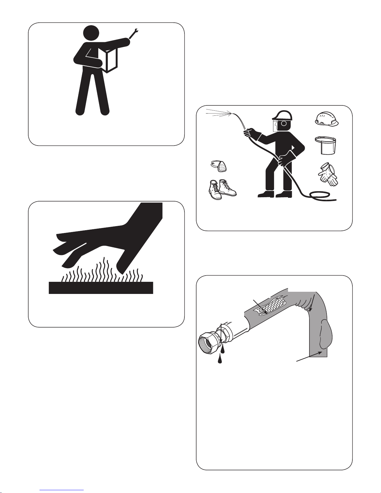
At operating temperature, the engine, exhaust
system components, cooling system
components and hydraulic system components
are HOT. Any contact can cause severe burns.
When servicing or replacing hardened steel pins,
use a brass drift or other suitable material between
the hammer and pin if it must be driven into the
pivot. Use safety glasses or other suitable eye
protection.
DO NOT make adjustments while the machine is
moving or the engine is running unless otherwise
specified to do so.
DO NOT change the pressure setting on any
hydraulic valve without authorized instruction.
Pressurized air can cause personal injury.
When using pressurized air for cleaning, wear
protective clothing, face shield and shoes.
The maximum allowed air pressure used for
cleaning purposes should not exceed 30 psi
(205 kPa).
Evidence of Kinking
Chaffing or Cuts,
Wire Exposed
Damaged or
Leaking Fitting
Localized
Ballooning
Check hoses carefully. Do not use your
Disce hands to check for leaks. See “Fluid
Penetration”. Tighten all connections to recommended torque. Replace if any of the following
are found:
- End fittings damaged or leaking.
- Outer covering chafed or cut and wire
reinforcing exposed.
or Crushing
00032
Use all cleaning solutions with care. Avoid
breathing vapors and contact with eyes and skin
- Outer covering ballooning locally.
- Hose shows evidence of kinking or crushing.
7
Operation, Maintenance, and Parts
Page 8
Pressure can be maintained in system circuits
long after the engine and pumps have been shut
down. Release trapped pressure in hydraulic,
fuel, and cooling system lines before performing
any maintenance or repair procedures.
Hydraulic System
00012
Disc Saw Safety Information
It is essential that all operators of the disc-felling
head become familiar with all aspects of its correct operation.
1. Remember at all times that the disc saw blade,
at operational speed carries a tremendousamount of stored energy. Tooth tip speeds can be
up to 17000 ft/min. Flying chips or other debris
can cause serious injury. Do not approach the
felling head unless the disc saw blade has come
to a complete stop, and the engine has been
shut down.
2. During operation of the disc felling head, all
personnel not in the machine should remain at
least 300’ away and never cross in front of the
saw opening.
Do not bend or install bent or damaged hydraulic
hoses and tubelines.
Do not strike hydraulic hoses or tubelines.
Be sure all hose clamps, guards and protective
wrapping is installed correctly to prevent vibration
and rubbing which could lead to hose failure.
00009
3. All observers should stand on the opposite side
of the disc rotation. In other words the opposite
side of the chip path from the primary opening.
4. As debris is always being released from the
saw-housing opening, the operator must remain
in the cab until blade has stopped rotating completely.
5. Saw operation speed should be respected. Do
not exceed maximum allowable r.p.m. Wait until
disc saw achieves full speed (see saw motor
RPM settings) before proceeding to cut.
6. Inspect saw blade at start of every shift and,
periodically during the shift. See daily inspection
information.
7. Shut saw off immediately if an imbalance occurs.
Imbalances can result from a bent disc, loose or
lost parts and can be indicative of a serious
problem. Inspect all parts of saw blade prior
to restarting. Do not operate saw blade in any
unbalanced condition.
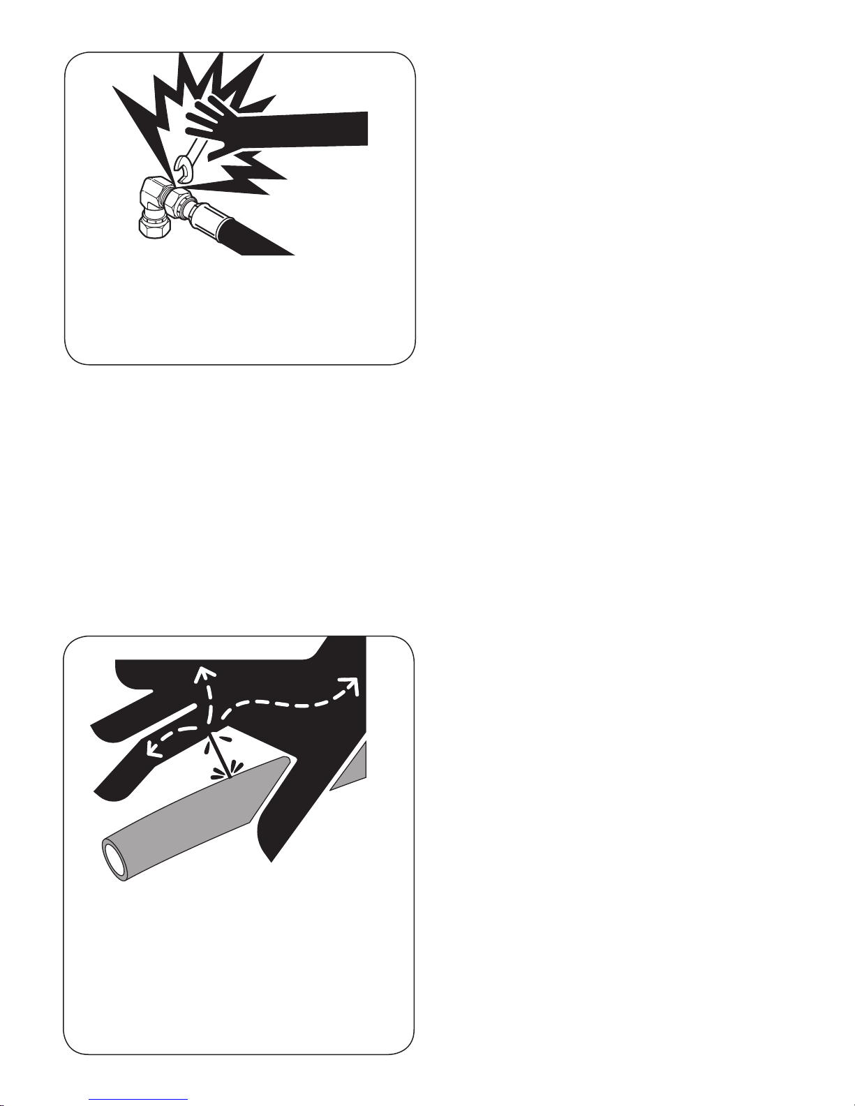
Hydraulic oil under pressure can penetrate body
tissue causing serious injury and possible death.
When troubleshooting a hydraulic system for
leaks, always use cardboard or other material as
a deflector. DO NOT USE YOUR HANDS.
If you are injected with hydraulic oil or any other
fluids, seek treatment by a doctor familiar with
this type of injury immediately.
Operation, Maintenance, and Parts
8. Do not work on blade or head while machine
is running, except when performing required
hydraulic checks.
8
Page 9
General Maintenance
Before performing any maintenance or
service work, lower the attachment to the
ground and shut off the engine. Turn off any
master shut-offs and do not allow personnel
in the cab
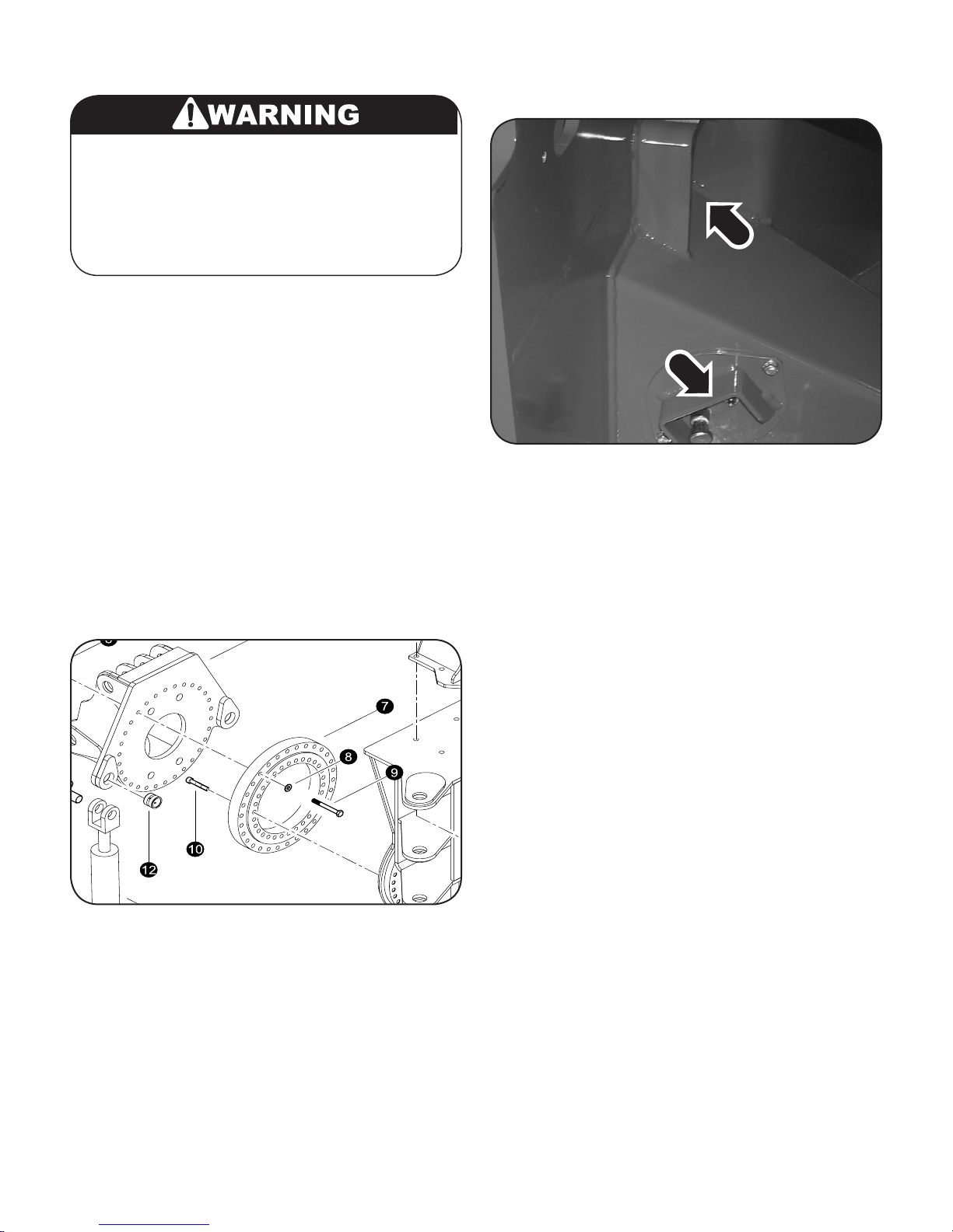
Re-torquing the boom Adapter Mounting
Bolts
The bolts of which hold the boom adapter
mounting bracket and bearing to the Disc saw
weldment should be re-torqued to 420 ft. lDS.
after a few hours of use and then again every
200 hours. There will be one ring of thirty (30)
3/4" allen bolts (item #10 below) that connect
the mount to the head and get torqued to Torque
to 377 ft.lDS (512 Nm) and one ring of standard
bolts (item #9 below) that secure the bearing to
the mount and get torqued to Torque to Torque
to 420 ft.lDS (570 Nm).
Lubrication and Grease
occur. Fill bearing cavities until grease begins to
expel from relief ttings.
Figure 2: Saw Drive Grease Fittings
Note that there is a plug at the center of the saw
disc mounting ange. This is an access hole for
a grease zerk that allows grease to reach the
splined adapter between the motor and shaft.
This should be greased every 500 hours.
Figure 1: Boom Adapter Mounting Bolts
Before start-up, make sure the saw head has
been greased. Every pin joint will have a grease
zerk. Each cylinder end will also have a grease
zerk.
Grease the saw drive daily at the beginning of
each shift (two separate cavities). Ensure grease
relief tting are functional. If relief ttings are not
functioning properly, damage to shaft seals may
Disc Saw Daily Inspections
1. Check lower portion of shaft for grease leaks.
Repair damaged seals if required.
2. Check end shaft for end play. (.006” - .008”
allowance)
3. Check saw retaining bolts on lower ange
once at a 100 hour inspection, and every
2000 hours after that for correct torque. (320
lb./ ft)
4. Inspect and Clean debris between saw
blade, housing and guard.
5. Check disc housing guarding for damage
and blade contact. Make necessary repairs
when needed.
6. Check saw head regularly for cracks. Repair
any damage.
7. Inspect hydraulic hoses, ttings and cylinders for damage or wear. Replace or repair
if necessary.
8. Inspect cutting teeth for damage. Make sure
the teeth are in good shape and that all
mounting hardware is secure. Never mix dif-
9
Operation, Maintenance, and Parts
Page 10
ferent styles of cutting teeth. When teeth are
worn and damaged they should be replaced
as a matched set.
Operating Instructions
NOTE: When rst becoming familiar with the
disc saw felling head, tilt the head forward to the
vertical position when the saw is being started
or stopped.
saw head. This is done by tilting the head
using the "tool tilt" function into the direction
you would like to place the trees. Then opening all clamp arms to relase the trees.
7. When your nished using the disc saw turn
off the disc saw pump. Then either position
the disc saw in a place that is safe and free
of people or animals and monitor the disc
until it comes to a complete stop. You may
also use a near by stump to stop the disc.
Make sure and slowly pust the disc into the
stump until the disc stops.
1. Start the saw rotation, open accumulator
arms, open top grab just before you are
ready to cut a tree.
2. Tilt the head to the upright position and move
toward the rst tree.
3. As the cut is being made, the upper clamp
arms should begin to close, but should not
be completely closed until the cut is completed.
NOTE: It is important not to fully clamp the tree
until after the cut is complete. Clamping the tree
before the cut is complete, may cause damage
to the stem and unnecessary binding or stalling
down of the saw blade.
4. Once the tree is completely severed, the
head should be immediately raised off the
stump. This is important to avoid stalling
down of the saw blade.
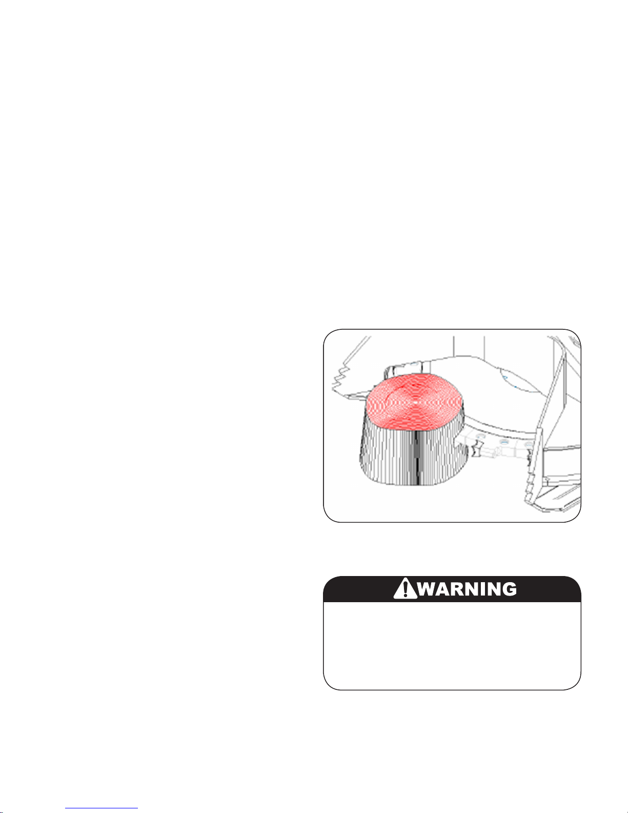
NOTE: When using a stump to stop the disc
make sure and push the disc into the stump using the same procedure as when your cutting a
tree. Never push downward on the stump with
the bottom of the disc. This can cause damage
to the disc and disc drive system. See gure 3
00481
NOTE: It is obvious that a smooth and continu-
ous feed speed of the saw will prevent binding
or stalling of the saw blade. Speed of cut must
be related to tree size and species.
5. When cutting smaller trees, at this time the
operator would then close the lower "accumulation" arms. This would ready the the
disc saw for the next cut.
NOTE: The lower "accumutlation" arms are
used to hold the smaller trees when opening the
upper arms to make the next cut.
6. Once done making a cut or multiple cuts, the
trees will be need to be dumped from the disc
Operation, Maintenance, and Parts
Figure 3: Correct Stopping Procedure
Never leave a disc saw still spinning and unattended. Even after a disc saw has been
shut off the disc will continue to spin with
enough force to cause injury or harm. Never
try to manually stop a disc that is spinning.
10
Page 11
Saw Motor RPM Adjustment
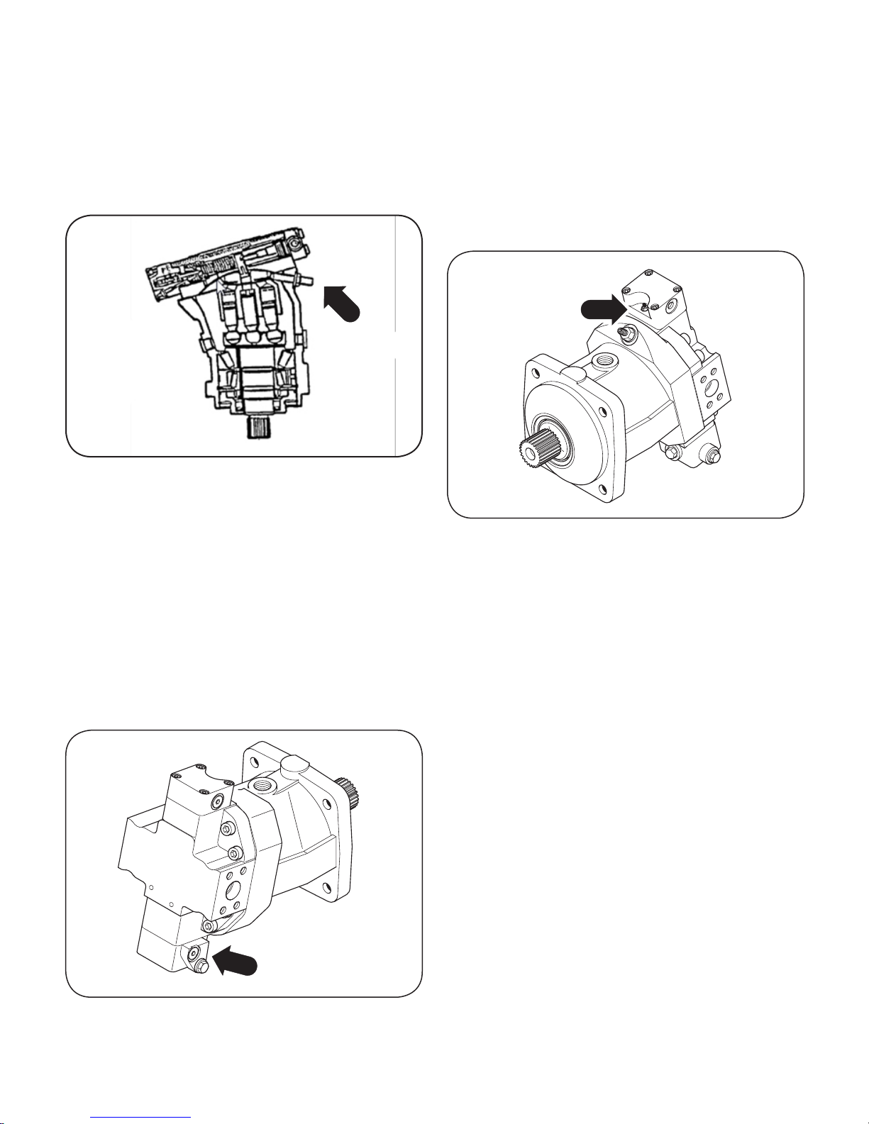
Ensure that the 100 mm (3.94 inch) long saw
speed adjustment screw (see gure 4) is turned
in until 19 mm (.75 inch) of the stud protrudes
beyond the jam nut. (This prevents over speeding the saw at initial start-up)
Install 5000 p.s.i. pressure gauges at saw valve
test port and at “G” port (# 4 ORB style) and
“M” port (# 6 ORB style see gure 5) of saw motor. Block saw blade rotation with pin in base
assembly saw housing.
With engine at full throttle adjust saw circuit relief valve to read 3800 psi at “G” port on saw
motor pressure inlet block.
Figure 4: Saw Drive Motor RPM
With saw free to rotate turn saw circuit ON and
bring engine to full throttle. Turn saw speed
adjustment screw out until saw speed is 1139
r.p.m. Lock jam nut on saw speed adjusting
screw.
Saw Motor Begin of Stroke
Adjustment
00482
Figure 6: Disc Motor Begin Of Stoke Adjustment
Locate begin of stroke adjustment screw (gure
6) through the hole at the rear of the head column or motor housing.
Turn the “begin of stroke” adjustment screw out
until the gauge in the “M” port reads 0 psi.
Then slowly turn the “begin of stroke” adjustment screw in until the pressure gauge in the
“M” port reads 1800-2000 psi. Lock jam nut on
adjusting screw.
Reset the pump pressure to recommended carrier specs. (4000 PSI)
Figure 5: Disc Saw Motor Port “M1”
00481
11
Operation, Maintenance, and Parts
Page 12
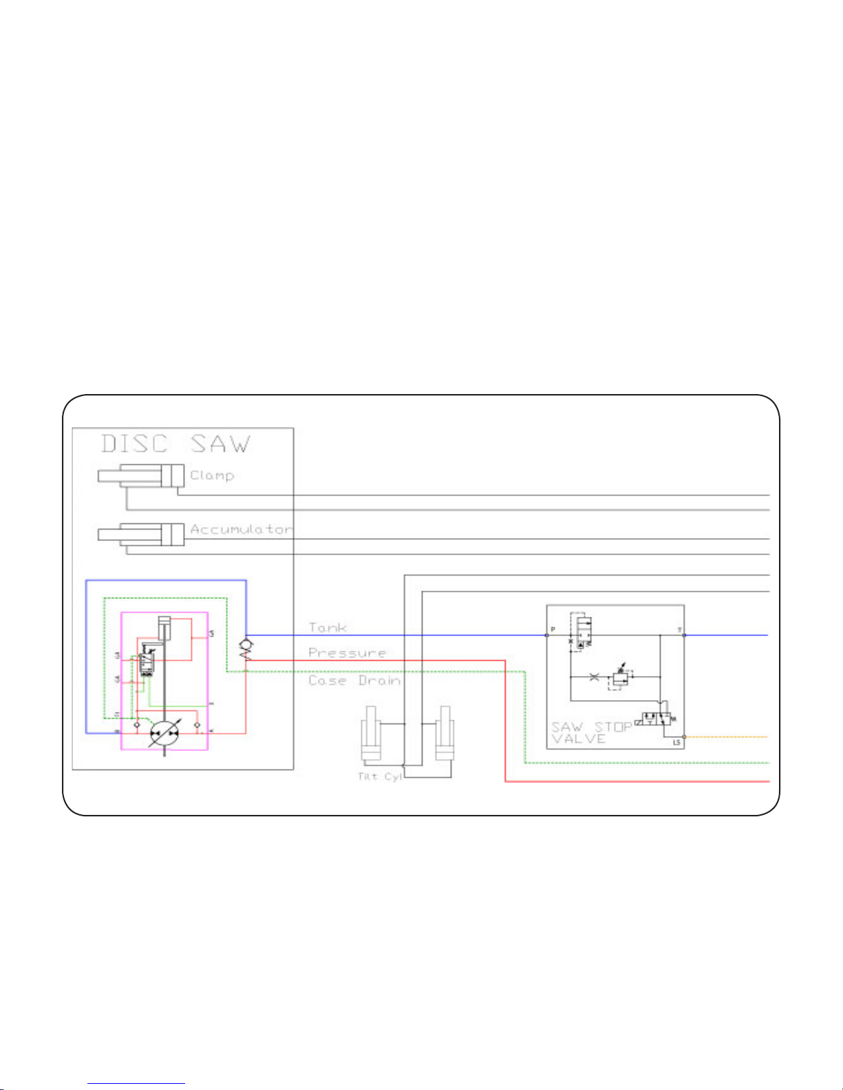
Disc Saw Hydraulics
Hydraulic pressure,
Saw motor.... 4000 Psi (276 Bar)
Hydraulic flow,
Saw motor.... 28 to 32 GPM (172 to 256 l/min)
Hydraulic pressure,
Clamps, Accumulator, and Tilt Cylinders
4000 Psi (276 Bar)
Operation, Maintenance, and Parts
Disc Saw Schematic
12
Page 13

Section DS-1
22” Disc Saw -
Parts Breakdown
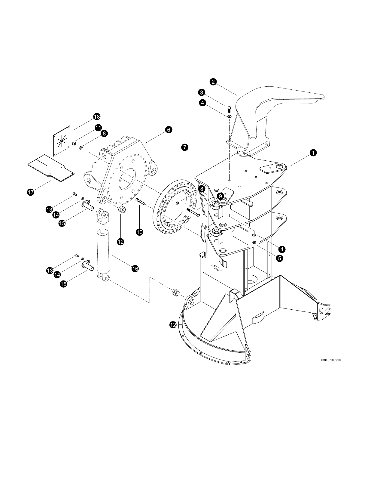
Disc Saw - Parts Breakdown
Page 14
Last Updated - 10/09
Disc Saw - Parts Breakdown
TimberPro Parts Module DS-R0
DS-1-1
Page 15

Disc Saw - Parts Breakdown
Last Updated - 10/09
MAIN PAGE HEADING
(Top Post and Boom Mount)
(Used on machines PDN# 000FWD and above)
REF PART # QTY DESCRIPTION SEE PAGE
REF PART # QTY DESCRIPTION SEE SECTION
Disc Saw
(Page Sub-Heading)
1 52789-DS 1 FRAME, Disc Saw
2 54112-DS 2 ASSEMBLY, TOP - Disc Saw
3 10775-DS 6 BOLT - .75” X 2.5”
4 15550-DS 12 WASHER, SAE FLAT - .75”
5 10817-DS 6 NUT, LOCK - .75”
6 53940-DS 1 BASE, SAW 40 DEG TILT DUAL CYL-53883 BRG
7 53883-DS 1 BEARING, LATERAL TILT DISC/Disc Saw
8 15550-DS 60 WASHER, SAE FLAT - .75”
9 10843-DS 30 BOLT - .75” X 4.5” (Torque to 420 ft.lDS (570 Nm))
10 53996-DS 30 BOLT, ALLEN HEAD - .75” X 4” (Torque to 377 ft.lDS (512 Nm)) (See Note: 1)
11 10776-DS 30 NUT, HEX - .75” (See Note: 1)
12 52795-DS 4 BUSHING - 2” X 2”
13 10783-DS 4 BOLT - .5” X 1”
14 15534-DS 4 WASHER, SAE FLAT - .5”
15 53775-DS 4 PIN ASSEMBLY,
16 52814-DS 2 CYLINDER, DISC SAW HEAD TILT - JARP . . . . . . . . . . . . . . . . . DS-2
17 54039-DS 1 BELTING, HOSE GUIDE - OUTSIDE
18 54038-DS 1 BELTING, HOSE GUIDE - INSIDE
See referenced page for component or assembly breakdown.
Note: 1
Use Loctite 272 (blue) during installation.
DS-1-2
TimberPro Parts Module DS-R0
Page 16
Last Updated - 10/09
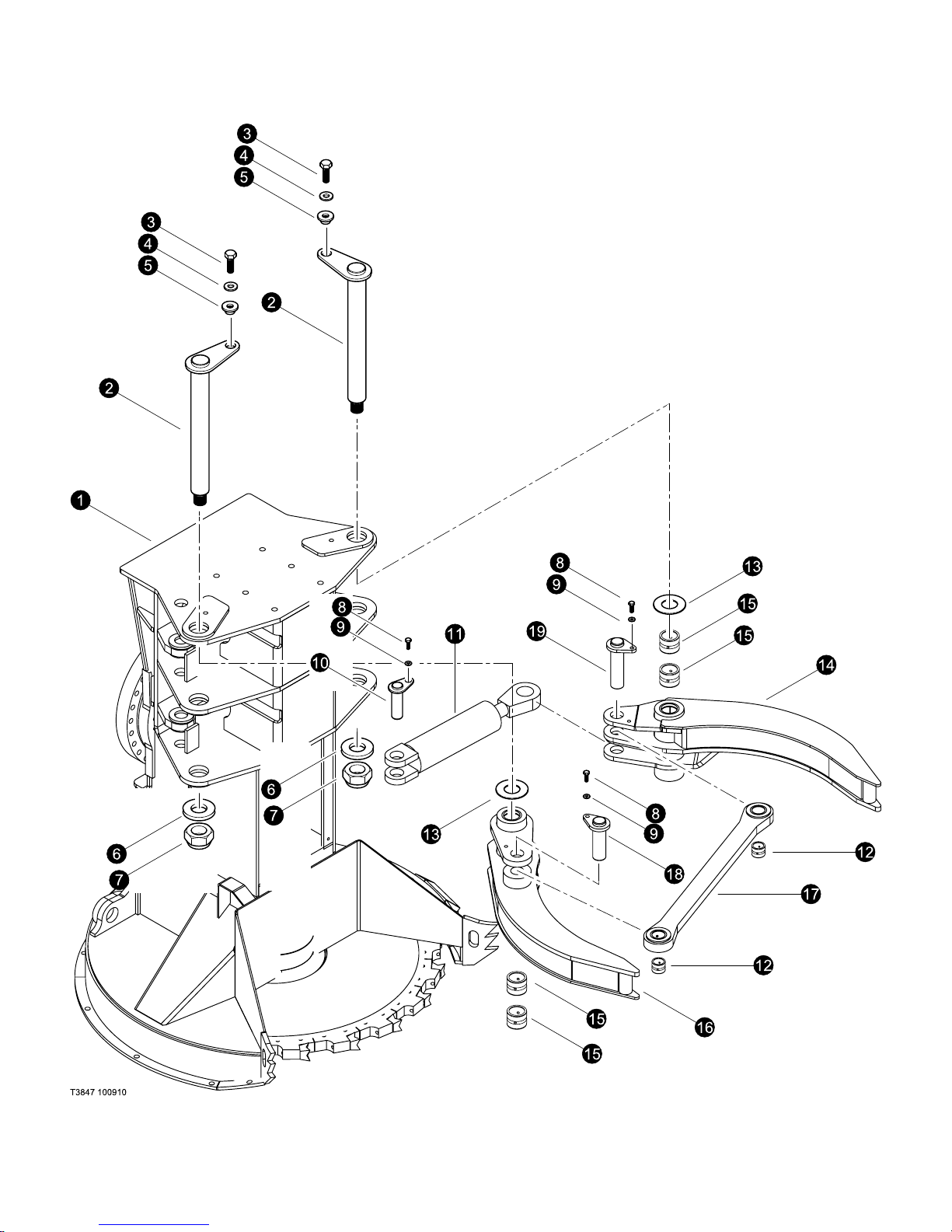
Disc Saw - Parts Breakdown
TimberPro Parts Module DS-R0
DS-1-3
Page 17

Disc Saw - Parts Breakdown
Last Updated - 10/09
MAIN PAGE HEADING
(Used on machines PDN# 000FWD and above)
REF PART # QTY DESCRIPTION SEE PAGE
REF PART # QTY DESCRIPTION SEE SECTION
Disc Saw
(Page Sub-Heading)
(Clamp Arms)
1 REF. 1 Disc Saw FRAME . . . . . . . . . . . . . . . . . . . . . . . . . . . . . . . . . . . . . DS-1
2 54119-DS 2 PIN ASSEMBLY, Disc Saw Top Arms
3 15549-DS 2 BOLT - .75” X 2.0
4 15550-DS 2 WASHER, SAE FLAT - .75”
5 18570-DS 2 WASHER, PIN RETAINING (BRAATZ)
6 12021-DS 2 WASHER, BURNED 2 X
7 10728-DS 2 NUT, nylock - 2”
8 10739-DS 3 BOLT - .5” X 1.5”
9 15534-DS 3 WASHER, SAE FLAT - .5”
10 54120-DS 2 PIN ASSEMBLY, 2.0 DIA X 4.13
11 REF 1 CYLINDER, UPPER CLAMP . . . . . . . . . . . . . . . . . . . . . . . . . . . . . DS-2
12 52795-DS 2 BUSHING,
13 16266-DS 3 SHIM - 2.51” ID X 3.88” OD X .075” THK
- 16267-DS SHIM - 2.51” ID X 3.88” OD X .135” THK
- 16268-DS SHIM - 2.51” ID X 3.88” OD X .179” THK
14 54055-DS 1 ARM, TOP CLAMP - DOGBONE
15 11704-DS 4 BUSHING - 2.5” X 4.25”
16 54054-DS 1 ARM, TOP CLAMP - CYLINDER
17 54020-DS 1 ASSEMBLY, DOG BONE-DISC SAW ARMS
18 54121-DS 1 PIN ASSEMBLY, DISC SAW DOGBONE/CLAMP
19 54120-DS 1 PIN ASSEMBLY, DISC SAW ARM/CYLINDER
See referenced page for component or assembly breakdown.
DS-1-4
TimberPro Parts Module DS-R0
Page 18
Last Updated - 10/09
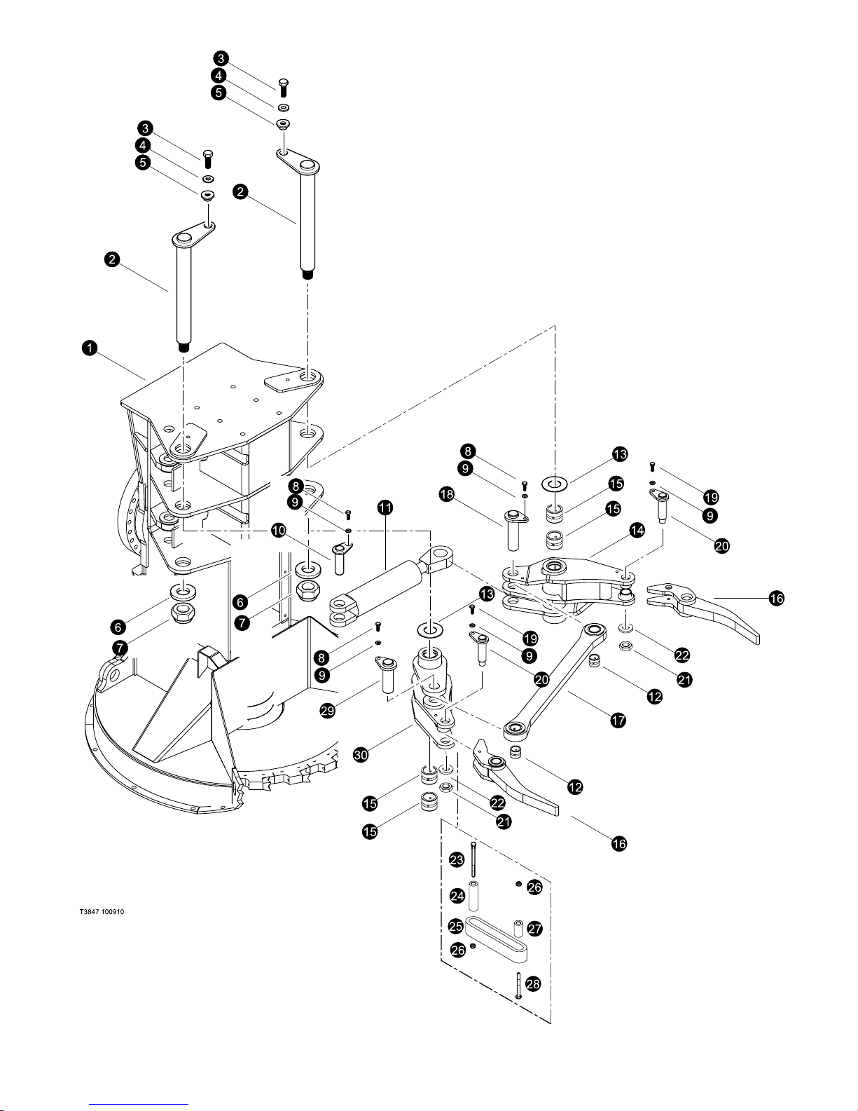
Disc Saw - Parts Breakdown
TimberPro Parts Module DS-R0
DS-1-5
Page 19

Disc Saw - Parts Breakdown
Last Updated - 10/09
MAIN PAGE HEADING
(Accumulator Arms)
(Used on machines PDN# 000FWD and above)
REF PART # QTY DESCRIPTION SEE PAGE
REF PART # QTY DESCRIPTION SEE SECTION
Disc Saw
(Page Sub-Heading)
1 REF. 1 Disc Saw FRAME . . . . . . . . . . . . . . . . . . . . . . . . . . . . . . . . . . . . . DS-1
2 54119-DS 2 PIN ASSEMBLY, Disc Saw Top Arms
3 15549-DS 2 BOLT - .75” X 2.0
4 15550-DS 2 WASHER, SAE FLAT - .75”
5 18570-DS 2 WASHER, PIN RETAINING (BRAATZ)
6 12021-DS 2 WASHER, BURNED 2 X
7 10728-DS 2 NUT, nylock - 2”
8 10739-DS 3 BOLT - .5” X 1.5”
9 15534-DS 3 WASHER, SAE FLAT - .5”
10 54120-DS 2 PIN ASSEMBLY, 2.0 DIA X 4.13
11 REF 1 CYLINDER, UPPER CLAMP . . . . . . . . . . . . . . . . . . . . . . . . . . . . . DS-2
12 52795-DS 2 BUSHING,
13 16266-DS 3 SHIM - 2.51” ID X 3.88” OD X .075” THK
- 16267-DS SHIM - 2.51” ID X 3.88” OD X .135” THK
- 16268-DS SHIM - 2.51” ID X 3.88” OD X .179” THK
14 54052-DS 1 ARM, ACCUMULATOR BASE - CYLINDER
15 11704-DS 4 BUSHING - 2.5” X 4.25”
16 54056-DS 2 ARM, ACCUMULATOR - END
17 54020-DS 1 ASSEMBLY, DOG BONE-DISC SAW ARMS
18 54120-DS 1 PIN ASSEMBLY, DISC SAW ARM/CYLINDER
19 50100-DS 2 BOLT - .5” X 1.25”
20 54123-DS 2 PIN ASSEMBLY, DISC SAW ACCUM ARM
21 20811-BS 2 NUT, NYLOCK - 1.5” NF (JAM)
22 19613-BS 1 WASHER, SAE FLAT - 1.5” . . . . . . . . . . . . . . . . . . . . . . . . . . . . . .
23 -DS 2 BOLT - .5” X 6.5”
24 54089-DS 2 SPACER, 1.06 X .68 X 3.93
25 53997-DS 2 RUBER BAND, ACCUMULATOR ARM
26 10815-DS 4 NUT, LOCK - .5”
27 54180-DS 2 SPACER, 1.06 X .68 X 2.0 LG
28 10893-DS 2 BOLT - .5” X 3”
29 54122-DS 1 PIN ASSEMBLY, DISC SAW DOGBONE/ACCUM
30 54053-DS 1 ARM, ACCUMULATOR BASE - DOGBONE
See referenced page for component or assembly breakdown.
DS-1-6
TimberPro Parts Module DS-R0
Page 20
Last Updated - 10/09
Disc Saw - Parts Breakdown
TimberPro Parts Module DS-R0
DS-1-7
Page 21

Disc Saw - Parts Breakdown
Last Updated - 10/09
MAIN PAGE HEADING
(Used on machines PDN# 000FWD and above)
REF PART # QTY DESCRIPTION SEE PAGE
REF PART # QTY DESCRIPTION SEE SECTION
Disc Saw
(Page Sub-Heading)
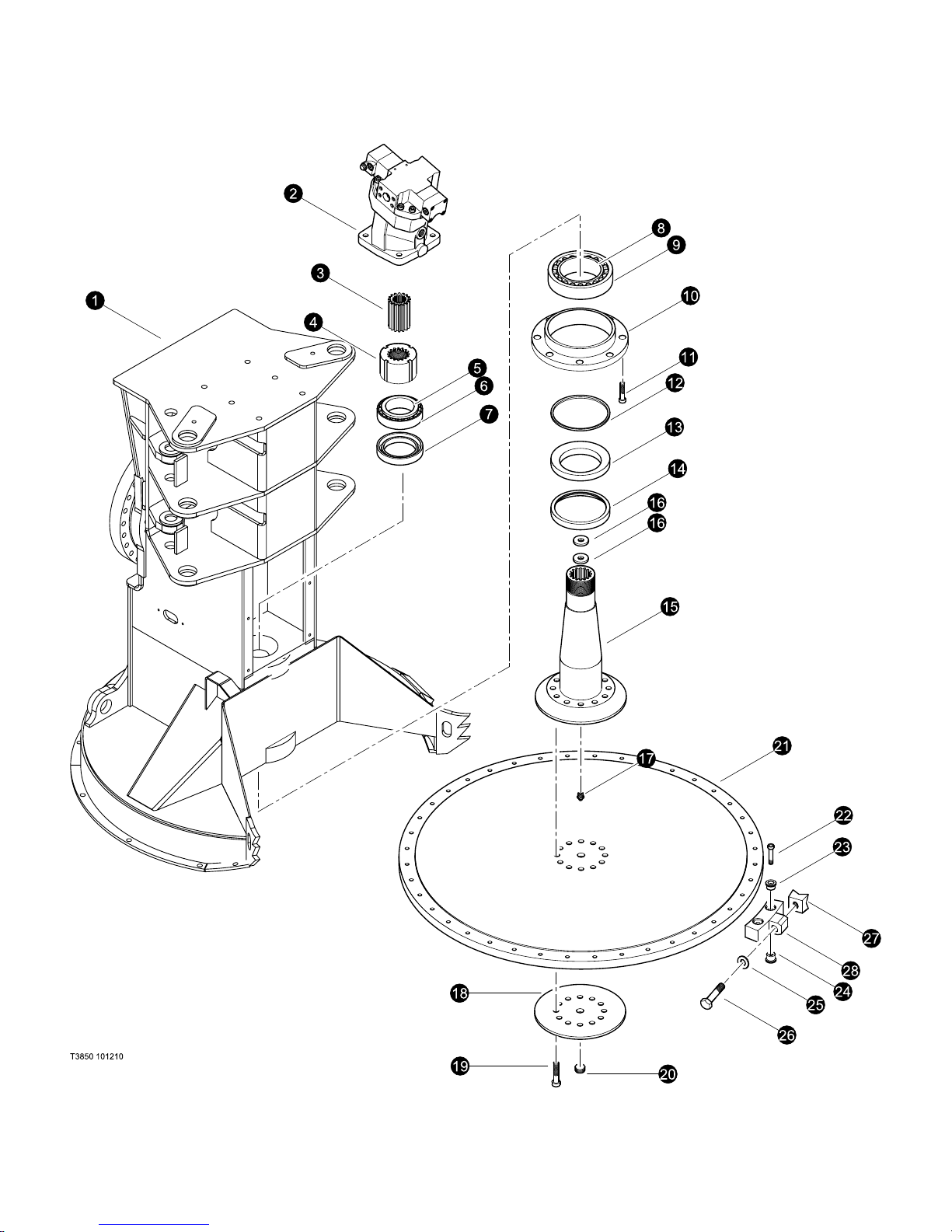
(Disc Install)
1 REF. 1 Disc Saw FRAME . . . . . . . . . . . . . . . . . . . . . . . . . . . . . . . . . . . . . DS-1
2 REF. 1 MOTOR, DISC SAW - AA6VM160 . . . . . . . . . . . . . . . . . . . . . . . . DS-2
3 54229-DS 1 SPLINED ADAPTER ASS’Y
4 54230-DS 1 LOCK NUT
5 54209-DS 1 BEARING CONE (Timken 6580)
6 54210-DS 1 BEARING CUP (Timken 6535)
7 54213-DS 1 SHAFT SEAL (National 415991)
8 54212-DS 1 BEARING CUP (Timken 67390)
9 54211-DS 1 BEARING CONE (Timken 67322)
10 54232-DS 1 BEARING CARRIER
11 50074-DS 8 BOLT, ALLEN HEAD - .5” X 1.5”
12 54231-DS 1 SEAL SPACER
13 54236-DS 1 SHAFT SEAL (National 417562)
14 54235-DS 1 SEAL RING
15 54227-DS 1 DRIVE SHAFT ASS’Y
16 54233-DS 2 WASHER - BEVELED
17 A21610 1 GREASE NIPPLE
18 54234-DS 1 BOLTING FLANGE
19 24915-DS 12 BOLT, ALLEN HEAD - .75” X 3”
20 04160816 1 SET SCREW
21 54151-DS 1 SAW DISC ASSEMBLY
- -DS 1 DISC
22 02101820 36 CAP SCREW
23 Q10014 36 SLEEVE (TOP)
24 Q10015 36 SLEEVE (BOOTOM)
25 Q10169 18 LOCK WASHER
26 011614648 18 HEX. HD. BOLT
27 Q10233T 18 TOOTH
28 Q10899 18 TOOTH HOLDER
See referenced page for component or assembly breakdown.
Kit or Assembly - includes all items indented underneath.
DS-1-8
TimberPro Parts Module DS-R0
Page 22
Last Updated - 10/09
Disc Saw - Parts Breakdown
TimberPro Parts Module DS-R0
DS-1-9
Page 23

Disc Saw - Parts Breakdown
Last Updated - 10/09
MAIN PAGE HEADING
(Used on machines PDN# 000FWD and above)
REF PART # QTY DESCRIPTION SEE PAGE
REF PART # QTY DESCRIPTION SEE SECTION
Disc Saw
(Page Sub-Heading)
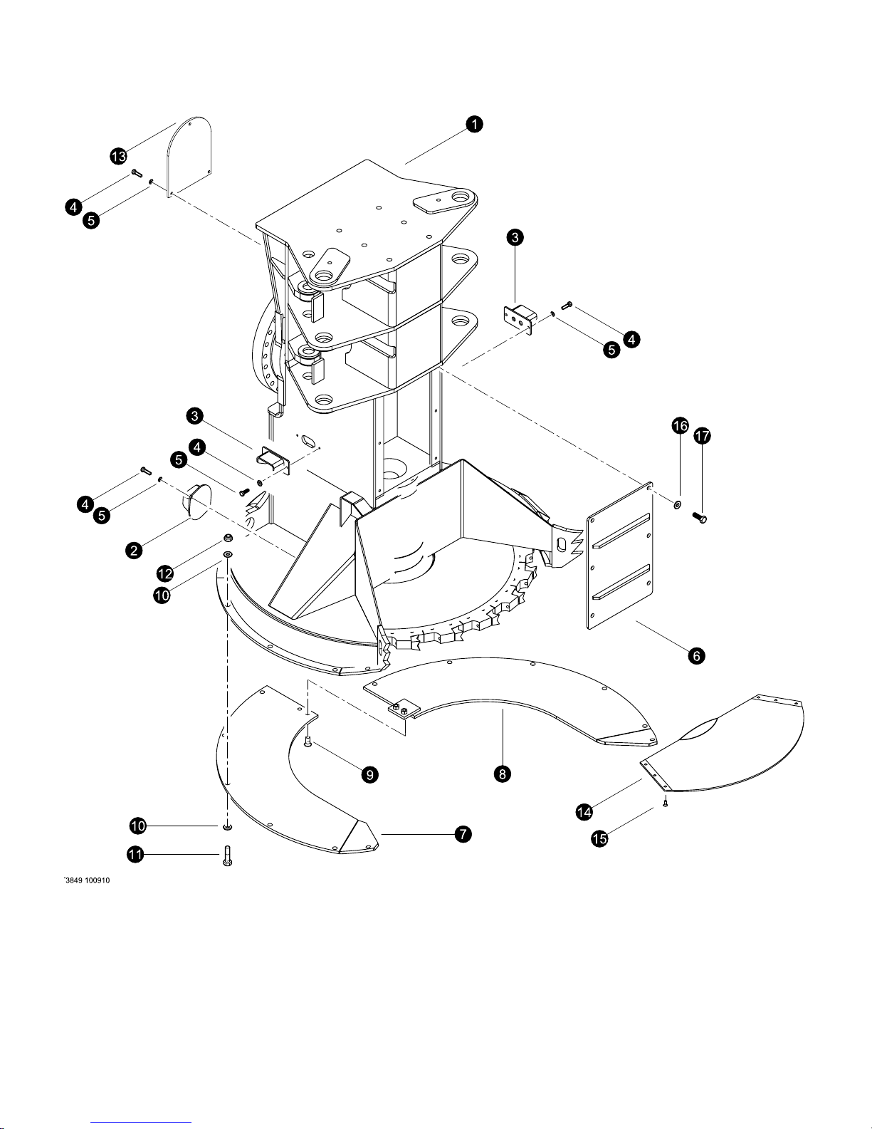
(Covers)
1 REF. 1 Disc Saw FRAME . . . . . . . . . . . . . . . . . . . . . . . . . . . . . . . . . . . . . DS-1
2 54027-DS 1 COVER, VENT SIDE
3 54048-DS 2 MOUNT, BULKHEAD DISC SAW
4 15528-DS 9 WASHER, SAE FLAT - .375”
5 15542-DS 9 BOLT - .375” X .75”
6 54047-DS 1 COVER, DISC SAW MOTOR
7 53765-DS 1 ASSEMBLY, BOTTOM COVER R.H.
8 53766-DS 1 ASSEMBLY, BOTTOM COVER L.H.
9 54036-DS 2 BOLT, FLAT HEAD SOCKET 3/4-10X1 1/2 DISC
10 15550-DS 24 WASHER, SAE FLAT - .75”
11 15549-DS 12 BOLT - .75” X 2.0
12 10776-DS 12 NUT, HEX - .75”
13 54195-DS 1 COVER, DISC SAW TOP
14 54168-DS 1 SHELF, LOG - DISC SAW
15 -DS 6 BOLT, FLAT HEAD
16 15534-DS 6 WASHER, SAE FLAT - .5”
17 10783-DS 6 BOLT - .5” X 1”
See referenced page for component or assembly breakdown.
DS-1-10
TimberPro Parts Module DS-R0
Page 24

Last Updated - 10/09
Disc Saw - Parts Breakdown
THIS PAGE LEFT BLANK FOR NOTES
TimberPro Parts Module DS-R0
DS-1-9
Page 25

Section DS-2
22” Disc Saw -
Hydraulics
Disc Saw - Parts Breakdown
Page 26
Last Updated - 10/10
Disc Saw - Hydraulics
TimberPro Parts Module DS-R0
DS-2-1
Page 27

Disc Saw - Hydraulics
MAIN PAGE HEADING
DISC SAW HYDRAULICS
(Page Sub-Heading)
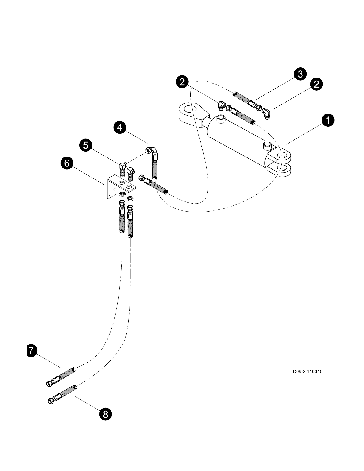
(Clamp Arm Cylinders)
(Used on machines PDN# 000FWD and above)
REF PART # QTY DESCRIPTION SEE PAGE
REF PART # QTY DESCRIPTION SEE SECTION
Last Updated - 10/10
1 REF 1 CYLINDER, SAW CLAMP ............................... DS-2
2 16360-DS 4 ELBOW, 90° - FF1868T-0808S
3 -DS 1 HOSE ASSEMBLY - 4021-08-080S-0809w (bulkhead to clamp cylinder
base port)
4 -DS 1 HOSE ASSEMBLY - 4024-08-080S-080Sw (bulkhead to clamp cylinder
rod port)
5 24187-DS 2 ELBOW, 90 BULKHEAD - 855BH-TT-08
6 54196-DS 1 BRACKET, CLAMP BULKHEAD
7 -DS 1 HOSE ASSEMBLY - 4099-08-080S-080Sw (clamp rod bulkhead to boom)
8 -DS 1 HOSE ASSEMBLY - 4102-08-080S-080Sw (clamp base bulkhead to boom)
See referenced page for component or assembly breakdown.
Kit or Assembly - includes all items indented underneath.
DS-2-2
TimberPro Parts Module DS-R0
Page 28
Last Updated - 10/10
Disc Saw - Hydraulics
TimberPro Parts Module DS-R0
DS-2-3
Page 29

Disc Saw - Hydraulics
MAIN PAGE HEADING
DISC SAW HYDRAULICS
(Page Sub-Heading)
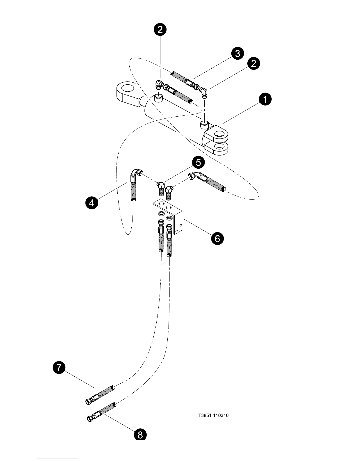
(Accumulator Cylinder)
Last Updated - 10/10
(Used on machines PDN# 000FWD and above)
REF PART # QTY DESCRIPTION SEE PAGE
REF PART # QTY DESCRIPTION SEE SECTION
1 REF 1 CYLINDER, SAW ACCUMULATOR ....................... DS-2
2 16360-DS 4 ELBOW, 90° - FF1868T-0808S
3 -DS 1 HOSE ASSEMBLY - 4030-08-080S-0804w (bulkhead to ACC cylinder
base port)
4 -DS 1 HOSE ASSEMBLY - 4015-08-080S-0809w (bulkhead to ACC cylinder
rod port)
5 24187-DS 2 ELBOW, 90 BULKHEAD - 855BH-TT-08
6 54196-DS 1 BRACKET, ACC BULKHEAD
7 -DS 1 HOSE ASSEMBLY - 4105-08-080S-080Sw (ACC rod bulkhead to boom)
8 -DS 1 HOSE ASSEMBLY - 4106-08-080S-080S w (ACC base bulkhead to boom)
See referenced page for component or assembly breakdown.
Kit or Assembly - includes all items indented underneath.
DS-2-4
TimberPro Parts Module DS-R0
Page 30
Last Updated - 10/10
Disc Saw - Hydraulics
TimberPro Parts Module DS-R0
DS-2-5
Page 31

Disc Saw - Hydraulics
MAIN PAGE HEADING
DISC SAW HYDRAULICS
(Page Sub-Heading)
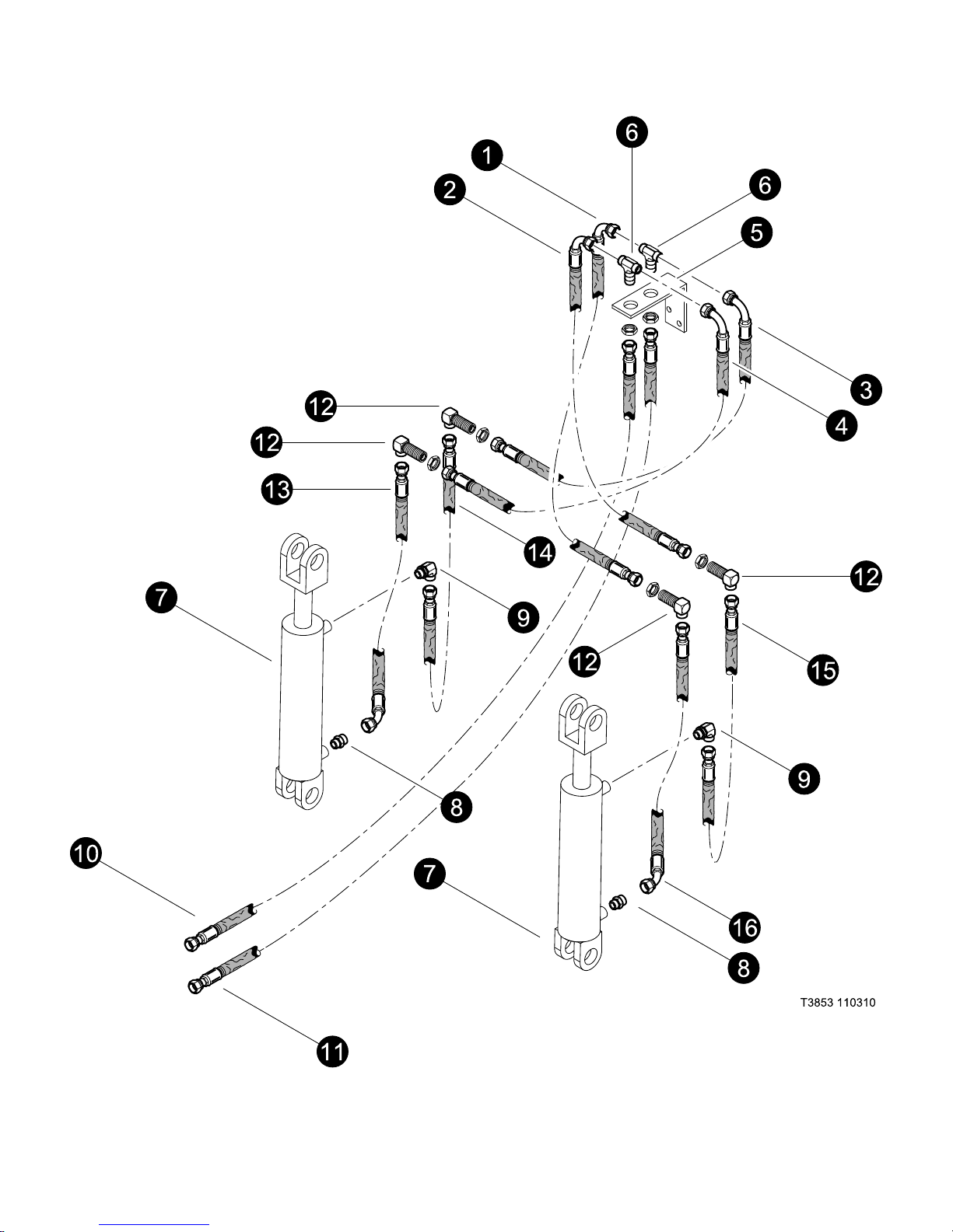
(Tilt Cylinder)
(Used on machines PDN# 000FWD and above)
REF PART # QTY DESCRIPTION SEE PAGE
REF PART # QTY DESCRIPTION SEE SECTION
Last Updated - 10/10
1 -DS 1 HOSE ASSEMBLY - 4042-08-080S-0809w (bulkhead tee
to bulkhead 90)
2 -DS 1 HOSE ASSEMBLY - 4042-08-080S-0809w (bulkhead tee
to bulkhead 90)
3 -DS 1 HOSE ASSEMBLY - 4042-08-080S-0809w (bulkhead tee
to bulkhead 90)
4 -DS 1 HOSE ASSEMBLY - 4042-08-080S-0809w (bulkhead tee
to bulkhead 90)
5 54197-DS 1 BRACKET, bulkhead
6 52930-DS 2 TEE, BULKHEAD BRANCH - 8
7 REF 1 CYLINDER, SAW HEAD UPPER CLAMP ................... DS-2
8 15117-DS 2 CONNECTOR, STR - FF1852T-0808S
9 16360-DS 2 ELBOW, 90 - FF1868T-0808S
10 -DS 1 HOSE ASSEMBLY - 4102-08-080S-080Sw (Rear bulkhead tee
to stick boom Tilt B)
11 -DS 1 HOSE ASSEMBLY - 4102-08-080S-080Sw (Front bulkhead tee
to stick boom Tilt A)
12 24187-DS 2 ELBOW, 90 BULKHEAD - 855BH-TT-08
13 -DS 1 HOSE ASSEMBLY - 2018-08-080S-080Sw (bulkhead 90
to cyl base)
14 -DS 1 HOSE ASSEMBLY - 2022-08-080S-080Sw (bulkhead 90
to cyl rod)
15 -DS 1 HOSE ASSEMBLY - 2022-08-080S-080Sw (bulkhead 90
to cyl rod)
16 -DS 1 HOSE ASSEMBLY - 2018-08-080S-080Sw (bulkhead 90
to cyl base)
See referenced page for component or assembly breakdown.
Kit or Assembly - includes all items indented underneath.
DS-2-6
TimberPro Parts Module DS-R0
Page 32
Last Updated - 10/10
Disc Saw - Hydraulics
TimberPro Parts Module DS-R0
DS-2-7
Page 33

Disc Saw - Hydraulics
MAIN PAGE HEADING
DISC SAW HYDRAULICS
(Page Sub-Heading)
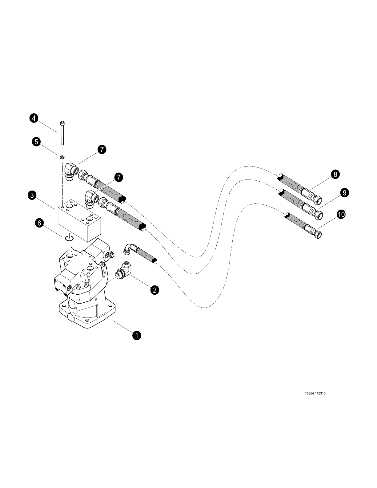
(Saw Motor Hydrualics)
(Used on machines PDN# 000FWD and above)
REF PART # QTY DESCRIPTION SEE PAGE
REF PART # QTY DESCRIPTION SEE SECTION
Last Updated - 10/10
1 REF 1 MOTOR, DISC SAW - AA6VM160 ........................ DS-2
2 15372-DS 1 ELBOW, 90 - FF1868T-0812S
3 53004-DS 1 MANIFOLD, ANTI-CAV ( DISC SAW MOTOR)
4 -DS 1 BOLT, ALLEN
5 -DS 1 WASHER, LOCK
6 -DS 1 O-RING,
7 17688-DS 3 ELBOW, 90 - FF1868T-1212S
8 -DS 1 HOSE ASSEMBLY - 4093 -12-120S-120Sw (Return)
9 REF 1 HOSE ASSEMBLY - 4085 -12-120S-120Sw (Pressure)
10 -DS 1 HOSE ASSEMBLY - 4112 -08-080S-080Sw (Case Drain)
See referenced page for component or assembly breakdown.
Kit or Assembly - includes all items indented underneath.
DS-2-8
TimberPro Parts Module DS-R0
Page 34
Last Updated - 10/10
Disc Saw - Hydraulics
TimberPro Parts Module DS-R0
DS-2-9
Page 35

Disc Saw - Hydraulics
MAIN PAGE HEADING
DISC SAW HYDRAULICS
(Page Sub-Heading)
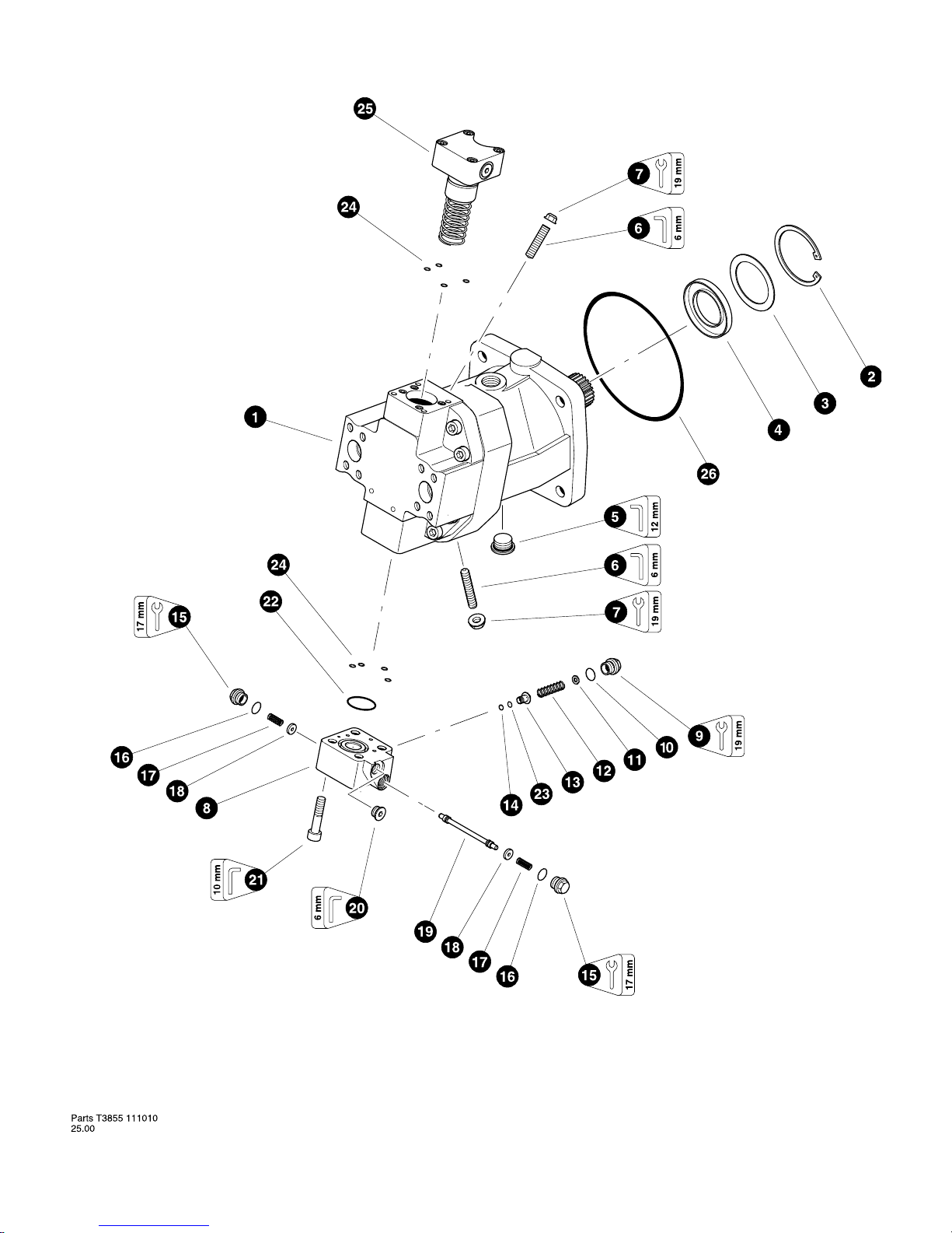
(Saw Motor)
(Used on machines PDN# 000FWD and above)
REF PART # QTY DESCRIPTION SEE PAGE
REF PART # QTY DESCRIPTION SEE SECTION
Last Updated - 10/10
1 53698-0-FF 1 MOTOR, DISC SAW - AA6VM160
2 20685-FF 1 RING, snap
3 20686-FF 1 SHIM, shaft seal
4 20687-FF 1 SEAL, shaft
5 19692-FF 1 PLUG - 26mm-1.5P (DSPP thread)
6 51987-FF 1 SCREW, adjusting (0 - Displacement min)(needed for front motor)
20688-FF 2 SCREW, adjusting (Displacement min & max)
7 20689-FF 2 NUT, seal
8 20690-FF 1 STROKING PISTON COVER ASSEMBLY
9 20691-FF 1 PLUG
10 20713-FF 1 O-RING
11 20714-FF 1 SHIM
12 20715-FF 1 SPRING
13 20716-FF 1 POPPET
14 20718-FF 1 RING, snap
15 20719-FF 2 PLUG
16 20720-FF 2 O-RING
17 20721-FF 2 SPRING
18 20722-FF 2 RETAINER, spring
19 NSS 1 SPOOL
20 20693-FF 1 PLUG - 14mm-1.5P (DSPP thread)
21 20723-FF 4 BOLT, allen head
22 20724-FF 1 O-RING
23 20717-FF 1 ORIFICE, flushing - 1.2mm
24 NSS 8 O-RING
25 REF. 1 STROKING PISTON CONTROL ASSEMBLY
26 20967-FF 1 O-RING, WHEEL DRIVE MOTOR (gearbox pilot)
- 20725-FF 1 KIT, seal repair - complete AA6VM160 motor
Kit or Assembly - includes all items indented underneath.
Included in seal repair kit Part # 20725-FF.
DS-2-10
TimberPro Parts Module DS-R0
Page 36
Last Updated - 10/10
Disc Saw - Hydraulics
TimberPro Parts Module DS-R0
DS-2-11
Page 37

Disc Saw - Hydraulics
MAIN PAGE HEADING
DISC SAW HYDRAULICS
(Page Sub-Heading)
(Clamp & ACC Cylinder)
(Used on machines PDN# 000FWD and above)
REF PART # QTY DESCRIPTION SEE PAGE
REF PART # QTY DESCRIPTION SEE SECTION
Last Updated - 10/10
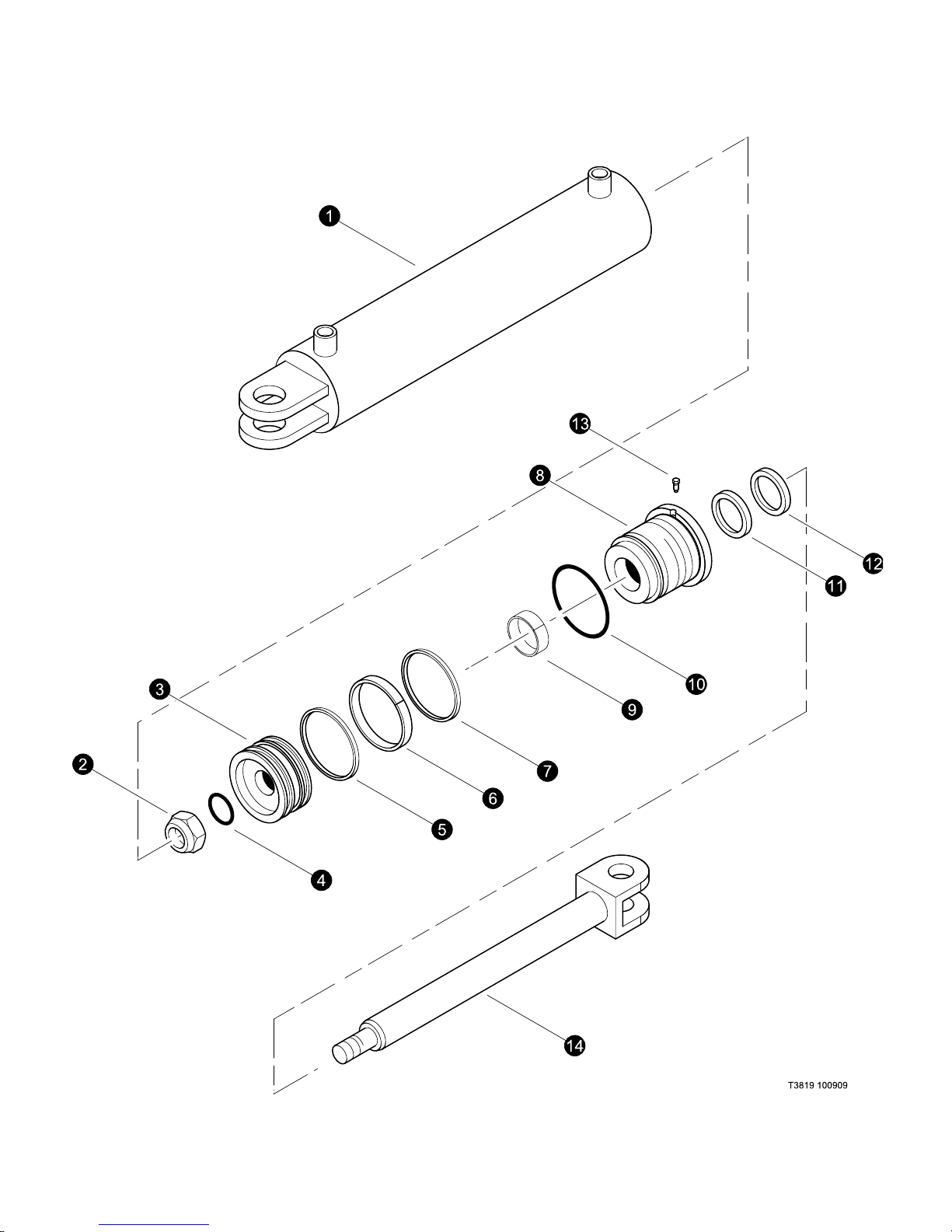
- 54107-BS 1 CYLINDER, SAW HEAD CLAMP/ACC (DISC SAW)
1 -BS 1 BARREL ASSEMBLY ()
2 -BS 1 NUT, SELF LOCKING (712025A)
3 -BS 1 PISTION ASSEMBLY (400450B)
4 -BS 1 Ë O-RING
5 -BS 1 Ë SEAL
6 -BS 1 Ë RING, piston wear
7 -BS 1 Ë SEAL
8 54554-BS 1 ROD BEARING ASSEMBLY (501024B)
9 -BS 1 Ë RING, rod bearing wear
10 -BS 1 Ë 0-RING
11 -BS 1 Ë SEAL
12 -BS 1 Ë DUST SEAL
13 -BS 1 SCREW - LOCKING (711127A)
14 -BS 1 ROD ASSEMBLY ()
- 54431-DS 1 KIT, Seal
See referenced page for component or assembly breakdown.
Kit or Assembly - includes all items indented underneath.
Ë Included seal kit # 54431.
DS-2-12
TimberPro Parts Module DS-R0
Page 38
Last Updated - 10/10
Disc Saw - Hydraulics
TimberPro Parts Module DS-R0
DS-2-13
Page 39

Disc Saw - Hydraulics
MAIN PAGE HEADING
DISC SAW HYDRAULICS
(Page Sub-Heading)
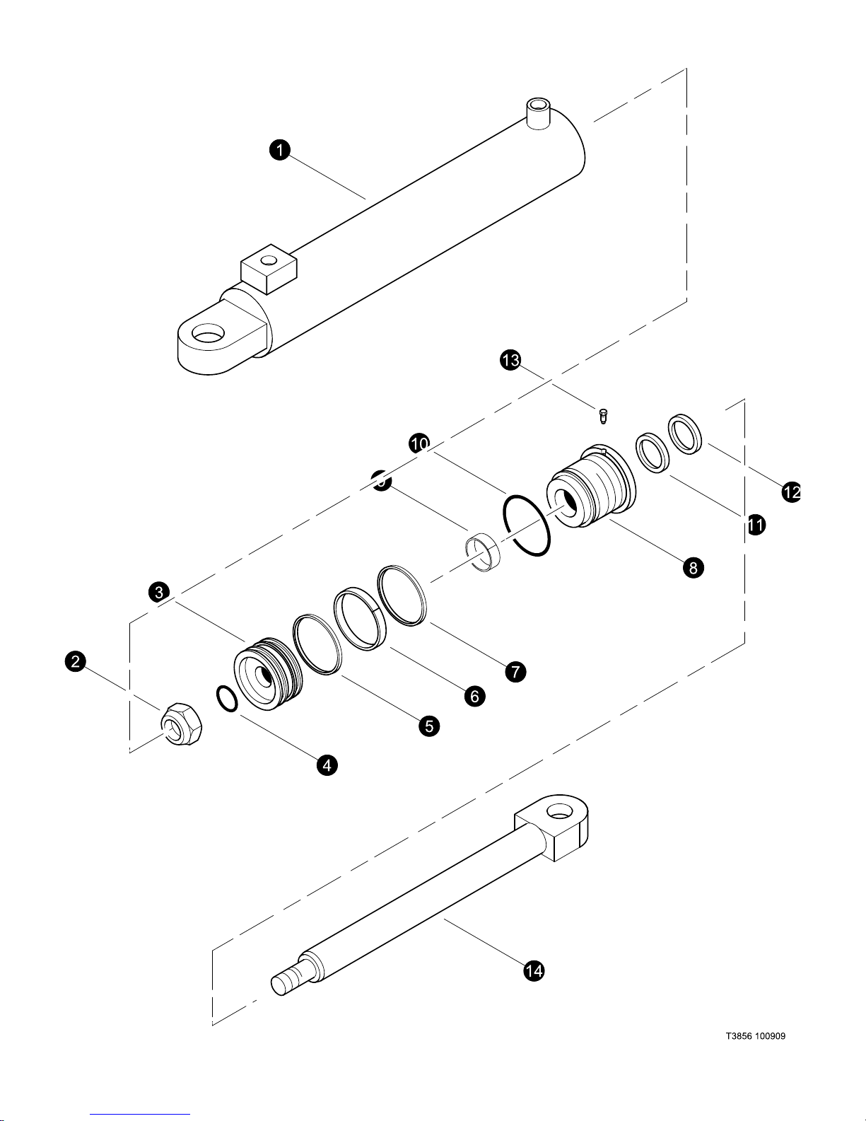
(Tilt Cylinder)
(Used on machines PDN# 000FWD and above)
REF PART # QTY DESCRIPTION SEE PAGE
REF PART # QTY DESCRIPTION SEE SECTION
Last Updated - 10/10
- 52814-BS 1 CYLINDER, SAW HEAD TILT
1 -BS 1 BARREL ASSEMBLY (203512B)
2 52659-BS 1 NUT, SELF LOCKING (712025A)
3 54155-BS 1 PISTION ASSEMBLY (400844B)
4 -BS 1 Ë O-RING
5 -BS 1 Ë SEAL
6 -BS 1 Ë RING, piston wear
7 -BS 1 Ë SEAL
8 54156-BS 1 ROD BEARING ASSEMBLY (501024B)
9 -BS 1 Ë RING, rod bearing wear
10 -BS 1 Ë 0-RING
11 -BS 1 Ë SEAL
12 -BS 1 Ë DUST SEAL
13 -BS 1 SCREW - LOCKING (711127A)
14 54154-BS 1 ROD ASSEMBLY (302180B)
See referenced page for component or assembly breakdown.
Kit or Assembly - includes all items indented underneath.
Ë Included seal kit # 54157.
DS-2-14
TimberPro Parts Module DS-R0
Page 40

Last Updated - 10/10
Disc Saw - Hydraulics
THIS PAGE LEFT BLANK FOR NOTES
TimberPro Parts Module DS-R0
DS-2-9
Page 41

Section DS-3
22” Disc Saw -
360 Rotate
Disc Saw - Parts Breakdown
Page 42
Last Updated - 10/09
Disc Saw - Parts Breakdown
TimberPro Parts Module DS-R0
DS-3-1
Page 43

Disc Saw - Parts Breakdown
Last Updated - 10/09
MAIN PAGE HEADING
(360 Degree Rotate)
(Used on machines PDN# 000FWD and above)
REF PART # QTY DESCRIPTION SEE PAGE
REF PART # QTY DESCRIPTION SEE SECTION
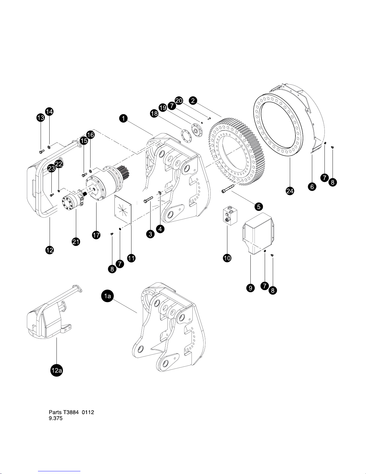
Disc Saw
(Page Sub-Heading)
1 54147-DS 1 ADAPTER, BOOM 360 DEG TILT-DUAL MOTOR
1a 54238-DS 1 ADAPTER, BOOM 360 DEG TILT-SINGLE MOTOR
2 54103-DS 1 BEARING, LATERAL TILT DISC/BAR SAW 360
3 10775-DS 30 BOLT - .75” X 2.5” (Torque to 420 ft.lDS (570 Nm))
4 15550-DS 60 WASHER, SAE FLAT - .75”
5 -DS 30 BOLT, ALLEN .75 X 5” (Torque to 420 ft.lDS (570 Nm))
6 54172-DS 1 COVER, BAND - GEAR
7 15528-DS 35 WASHER, SAE FLAT - .375”
8 15542-DS 19 BOLT - .375” X .75”
9 54179-DS 1 COVER, 360 ROTATE
10 54143-DS 1 MANIFOLD, CROSS-PORT LATERAL 360
11 54038-DS 1 BELTING, HOSE GUIDE - INSIDE
12 54184-DS 1 COVER, ROTATOR MOTORS - DUAL
12a 54452-DS 1 COVER, ROTATOR MOTORS - SINGLE
13 15502-DS 6 BOLT - .625” X 1.5”
14 10771-DS 6 WASHER, SAE FLAT - .625”
15 50100-DS 32 BOLT - .5” X 1.25”
16 15534-DS 32 WASHER, SAE FLAT - .5”
17 54175-DS 2 GEARBOX, 360 HEAD ROTATE
18 54178-DS 2 SHIM, 360 ROTATE .063 THICK
19 54169-DS 2 MOUNT, BACK BEARING - 360 ROTATE
20 11707-DS 16 BOLT - .375” X 1”
21 54114-DS 2 MOTOR, LATERAL TILT - BAR SAW (195 cc)
22 15534-DS 4 WASHER, SAE FLAT - .5”
23 18933-DS 4 BOLT - .5” X 1.75”
24 -DS 1 SPACER - 3/4” 360 Rotate
See referenced page for component or assembly breakdown.
DS-3-2
TimberPro Parts Module DS-R0
Page 44

Last Updated - 10/09
Disc Saw - Parts Breakdown
THIS PAGE LEFT BLANK FOR NOTES
TimberPro Parts Module DS-R0
DS-3-9
 Loading...