

Timberline Instruments TL-105-D Instruction Manual
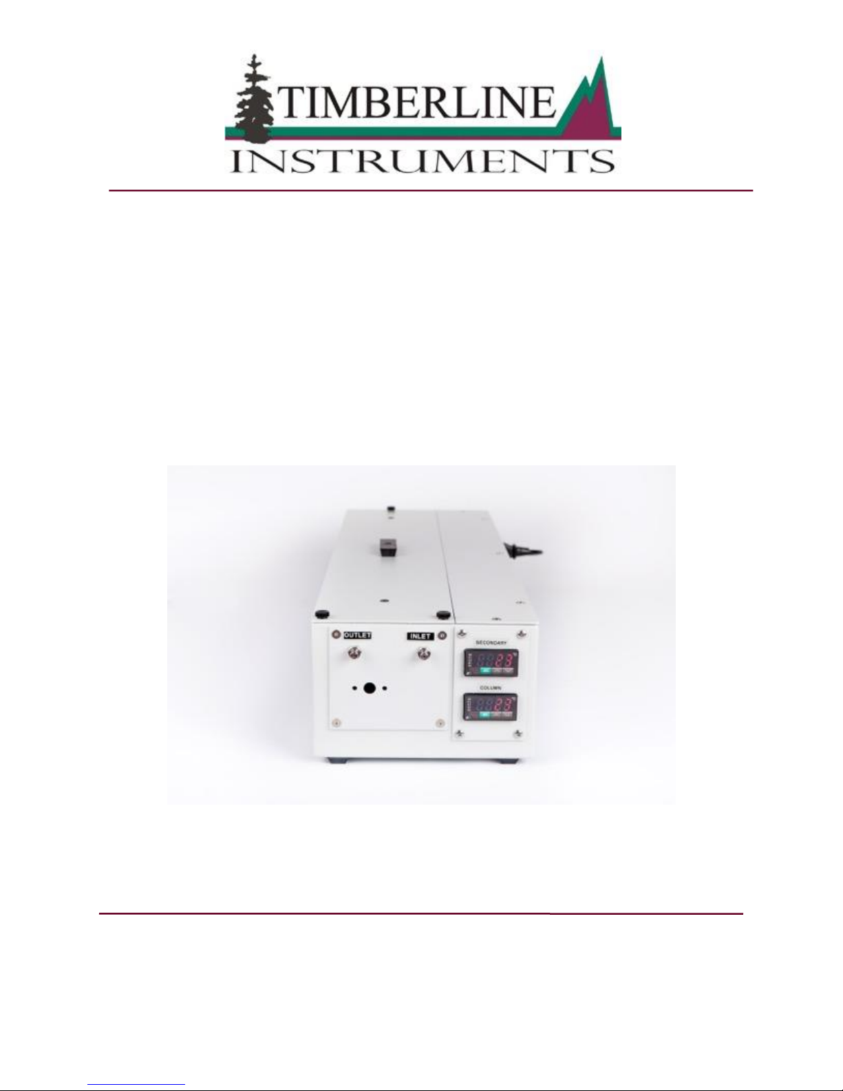
TL-105-D COLUMN HEATER
INSTRUCTION MANUAL
Timberline Instruments Inc.
1880 S. Flatiron Ct., Unit I
Boulder, Colorado 80301
Ph: (303) 440-8779
Fx: (303) 440-8786
info@timberlineinstruments.com
www.timberlineinstruments.com

- 2 -
Timberline Model TL-105-D Column Heater
Instruction Manual
TABLE OF CONTENTS
TABLE OF CONTENTS ................................................................................................................................ 2
TL-105-D FEATURES ................................................................................................................................... 3
PRINCIPLE OF OPERATION............................................................................................................................. 3
ADVANTAGES OF HPLC COLUMN TEMPERATURE CONTROL ........................................................................... 3
ELECTRICAL DESCRIPTION ............................................................................................................................ 3
Heater and Control Circuit Descriptions ................................................................................................. 3
Thermal Fuse Protection ........................................................................................................................ 3
Electrical Fuse Protection ....................................................................................................................... 3
MOBILE PHASE HEAT EXCHANGER ................................................................................................................ 4
INJECTION OR SELECTION VALVE................................................................................................................... 4
INSTALLATION ............................................................................................................................................. 5
CONNECTING THE TL-105-D ......................................................................................................................... 5
INSTALLING AN INJECTION OR SWITCHING VALVE............................................................................................ 5
CONNECTING THE COLUMN ........................................................................................................................... 6
CONNECTING THE DRAIN ............................................................................................................................... 6
OPERATING INSTRUCTIONS ..................................................................................................................... 6
SETTING THE TEMPERATURE ......................................................................................................................... 6
APPENDIX ..................................................................................................................................................... 7
SPECIFICATIONS ........................................................................................................................................... 7
ORDERING INFORMATION .............................................................................................................................. 7
WARRANTY .................................................................................................................................................. 8
SHIPMENTS .................................................................................................................................................. 8
DAMAGED SHIPMENTS .................................................................................................................................. 8
FILING OF CLAIMS ......................................................................................................................................... 8
RETURNS ..................................................................................................................................................... 8
INDEX .......................................................................................................................................................... 10

Timberline Instruments, Inc. - 3 - TL-105-D
TL-105-D FEATURES
PRINCIPLE OF OPERATION
Timberline’s Model TL-105-D Column Heater with integral mobile phase pre-heater is used in semipreparative HPLC applications where it is desirable to have independent temperature control of both the
column and mobile phase. The column heater provides temperature control with a stability of 0.1C.
Typical accuracy of the RTD sensor and controller is within 1C. The sophisticated microprocessor based
controller contains PID calibration capability and a high temperature shut off. The system is calibrated
before shipment and the PID constants are locked in memory.
ADVANTAGES OF HPLC COLUMN TEMPERATURE CONTROL
Controlling the temperature of HPLC columns has many advantages including
▪ Retention time stability
▪ Reduced detector noise and baseline drift
▪ Simplified method transfer
Elevating the column temperature can improve separations.
▪ Faster separation as retention decreases as temperature increases
▪ Improved peak shape by reducing on-column silanol effects
▪ Improved ion exchange efficiency
▪ Lower backpressures by to reduction in mobile phase viscosity
▪ Selectivity changes for better separations
ELECTRICAL DESCRIPTION
HEATER AND CONTROL CIRCUIT DESCRIPTIONS
The microprocessor base controller provides a 5-volt signal, actuating a solid-state relay which controls
power to the silicon heater. The controller sensor is a 100-ohm RTD probe inserted into a 0.14" hole in the
aluminum block. The RTD probe is placed very adjacent to the silicone heater to provide close temperature
control.
THERMAL FUSE PROTECTION
The heater is equipped with a secondary form of over temperature protection in a 12C thermal fuse. If a
failure occurs in the electronic circuitry, the thermal fuse will protect the apparatus against an over
temperature condition. The thermal fuse must be manually reset when an over temperature condition opens
the heater circuit. Contact Timberline for instructions.
ELECTRICAL FUSE PROTECTION
The standard configuration for 120V operation is two 4A, 250V fuse. The configuration for 240V operation
is two 2A, 250V fuses.
 Loading...