

Page 1

Technology Innovated Medicine
www.tim-gmbh.de
Technologie Institut Medizin GmbH (TIM)
MIRUS
TM
Controller
Instruction for use • Software version 2.00.00
www.tim-products.de
Page 2

User Responsibility
2 IFU, MIRUS Controller, en-GB, N.00
This product will perform in conformity with the description thereof contained in these
instructions for use and accompanying labels and/or inserts, when assembled, operated,
maintained and repaired in accordance with the instructions provided.
This product must be checked periodically. A defective product should not be used. Parts that
are broken, missing, clearly worn, distorted or contaminated should be replaced immediately.
Should repair or replacement become necessary contact your service organisation and return
the defective device to TIM for repair.
This product or any of its parts should not be repaired other than in accordance with written
instructions provided by TIM.
The product must not be altered without the prior written approval of TIM.
The user of this product shall have the sole responsibility for any malfunction which results
from improper use, faulty maintenance, improper repair, damage or alteration by anyone other
than TIM.
The product has a unit serial number (XXXD12345) with coded logic which indicates a product
group code (XXX), the year of manufacture (K = 2017, L = 2018 etc.) and a sequential unit
number for identification (12345).
MIRUS™ and are trademarks of Technologie Institut Medizin GmbH (TIM).
Other brand names or product names used in this manual are trademarks or registered
trademarks of their respective holders.
Page 3

0 Table of contents
IFU, MIRUS Controller, en-GB, N.00 3
0 Table of contents
1 Introduction ................................................................................ 6
1.1 Intended use ............................................................................................................ 6
1.2 Intended purpose ..................................................................................................... 6
1.3 Contraindications ..................................................................................................... 6
1.4 MIRUS System ........................................................................................................ 6
1.4.1 MIRUS Controller..................................................................................................... 7
1.4.2 Exchanger unit ......................................................................................................... 7
1.4.3 Device user interface ............................................................................................... 8
1.4.4 Colour code for the different volatile anaesthetic agents (VA) .................................. 8
1.4.5 Elements in touch screen ......................................................................................... 9
1.5 Symbols on the device ............................................................................................10
2 Safety ........................................................................................ 11
2.1 General safety instructions .....................................................................................11
2.1.1 Safe operation ........................................................................................................11
2.1.2 User qualification ....................................................................................................11
2.1.3 Monitoring ...............................................................................................................11
2.1.4 Electrical supply ......................................................................................................11
2.1.5 Responsibility of the manufacturer ..........................................................................12
2.1.6 Safety features .......................................................................................................12
2.2 Warning symbols used in the IFU ................................ ...........................................13
2.3 Patient safety ..........................................................................................................13
2.3.1 Monitoring ...............................................................................................................13
2.3.2 Volatile anaesthetic agents (VA) .............................................................................13
2.3.3 Control of patient relevant dosage ..........................................................................14
2.3.4 Combination of ventilators and MIRUS System ......................................................14
2.3.5 Triggering of ventilators ..........................................................................................14
2.3.6 Minimum tidal volume .............................................................................................14
2.3.7 MDI Applications .....................................................................................................15
2.3.8 Resistance of airway components ..........................................................................15
2.4 User’s and other patient’s safety .............................................................................15
2.5 Device ....................................................................................................................15
2.5.1 Accessories ............................................................................................................15
2.5.2 Positioning ..............................................................................................................16
2.5.3 Risk of electrical hazard ..........................................................................................16
2.5.4 Risk of fire ..............................................................................................................16
2.5.5 Electromagnetic compatibility .................................................................................17
2.6 Residual risk – Fail-safe mode ................................................................................17
3 Preparation ................................................................ ............... 18
3.1 Cleaning before first use .........................................................................................18
3.2 Connecting to mains supply ....................................................................................18
3.3 Connecting to MIRUS Reflector ..............................................................................19
3.4 Turning on ..............................................................................................................20
Page 4

0 Table of contents
4 IFU, MIRUS Controller, en-GB, N.00
3.5 Filling during start-up sequence ..............................................................................22
3.6 Anomaly in start-up sequence.................................................................................24
3.7 Change to operation mode .....................................................................................25
3.8 Changing patient data .............................................................................................25
3.8.1 Changing gender ....................................................................................................26
3.8.2 Changing age, size, weight .....................................................................................27
3.9 Changing wash-in speed ........................................................................................28
3.10 Changing alarm settings .........................................................................................29
3.11 Filling and additional configurations ........................................................................30
3.11.1 Filling during operation ...........................................................................................31
3.11.2 Setting on-screen language and CO2 unit ...............................................................33
3.11.3 Setting time.............................................................................................................34
3.11.4 Service screen ........................................................................................................36
3.12 Setting MAC value (Vol%) ......................................................................................36
3.13 Connecting patient ..................................................................................................37
4 Application of VA ..................................................................... 38
4.1 Starting application .................................................................................................38
4.2 Supervise patient respiratory data ..........................................................................39
4.3 Pausing application and reactivate .........................................................................39
4.4 Stopping application ...............................................................................................40
5 Turning off controller ............................................................... 41
6 Maintenance and Cleaning ...................................................... 43
6.1 Maintenance ...........................................................................................................43
6.1.1 General Information ................................................................................................43
6.1.2 Schedule ................................................................................................................43
6.2 Cleaning .................................................................................................................44
6.2.1 General advice .......................................................................................................44
6.2.2 Cleaning the individual components .......................................................................44
6.3 Draining the reservoir .............................................................................................46
6.4 Shipping MIRUS Controller .....................................................................................46
7 Alarms and messages.............................................................. 47
7.1 Alarms ....................................................................................................................47
7.1.1 Alarm modality ........................................................................................................47
7.1.2 Low -priority alarms .................................................................................................47
7.1.3 High-priority alarms .................................................................................................48
7.1.4 Patient alarms .........................................................................................................49
7.1.5 Technical alarms ....................................................................................................50
7.2 Messages and error messages ...............................................................................52
7.2.1 During power up test ...............................................................................................52
7.2.2 During system test ..................................................................................................53
7.2.3 Reminder screen ....................................................................................................54
7.2.4 During On-Call mode ..............................................................................................54
7.2.5 During operation mode ...........................................................................................54
Page 5

0 Table of contents
IFU, MIRUS Controller, en-GB, N.00 5
8 Standard values ........................................................................ 55
8.1 Alarm settings and application defaults ...................................................................55
8.2 Specification of wash-in speed parameters .............................................................56
9 Parts list .................................................................................... 57
9.1 Accessories ............................................................................................................57
9.2 Spare parts .............................................................................................................57
9.3 Service parts ...........................................................................................................57
9.4 Documents .............................................................................................................58
9.5 MIRUS Controller ....................................................................................................58
10 Technical specifications .......................................................... 59
10.1 General specifications ............................................................................................59
10.2 Controls and Ranges ..............................................................................................61
10.2.1 Agent dosage .........................................................................................................61
10.2.2 Alarm settings .........................................................................................................61
10.2.3 Patient data settings ...............................................................................................62
10.3 Performance ...........................................................................................................62
10.3.1 Agent dosage accuracy ..........................................................................................62
10.3.2 Respiratory monitoring accuracy .............................................................................62
10.3.3 Gas monitoring accuracy ........................................................................................63
10.4 Monitoring system ...................................................................................................63
11 Terms and abbreviations ......................................................... 64
12 High priority alarms ................................................................. 66
Page 6

1 Introduction
6 IFU, MIRUS Controller, en-GB, N.00
1 Introduction
1.1 Intended use
The MIRUS Controller is part of the MIRUS System. It is intended to be used for the application
of volatile anaesthetic agents to humans with a tidal volume of ≥ 200 mL.
1.2 Intended purpose
The MIRUS Controller is designed to work only in combination with the MIRUS Reflector. For
hygiene safety reasons connection of the MIRUS System to a patient is only possible via the
MIRUS Filter.
Note: For more information about the MIRUS Reflector and the MIRUS Filter please refer to
the manufacturer’s IFU.
1.3 Contraindications
Do not use the MIRUS System with
patients requiring less than 200 mL tidal volume.
patients that have a contraindication for the application of volatile anaesthetic
agents.
pure spontaneously breathing patients without a ventilator securing apnoea
back up ventilation mode.
jet or high frequency ventilation.
leaking patient airway systems, such as face mask or helmet systems.
additional filters (HME/F) or tubes that significantly increase dead space.
active humidification.
low flow anaesthesia.
1.4 MIRUS System
The MIRUS System consists of three devices:
MIRUS Controller (MC)
The electrical device that contains the anaesthetic agent and controls the agent
delivery.
MIRUS Reflector (MR)
The multi patient device connected to the MIRUS Controller, inserted into the
patient’s breathing system.
MIRUS Filter (MF)
The single patient device connected to the MIRUS Reflector, protecting the patient
and breathing system.
Page 7
1 Introduction
IFU, MIRUS Controller, en-GB, N.00 7
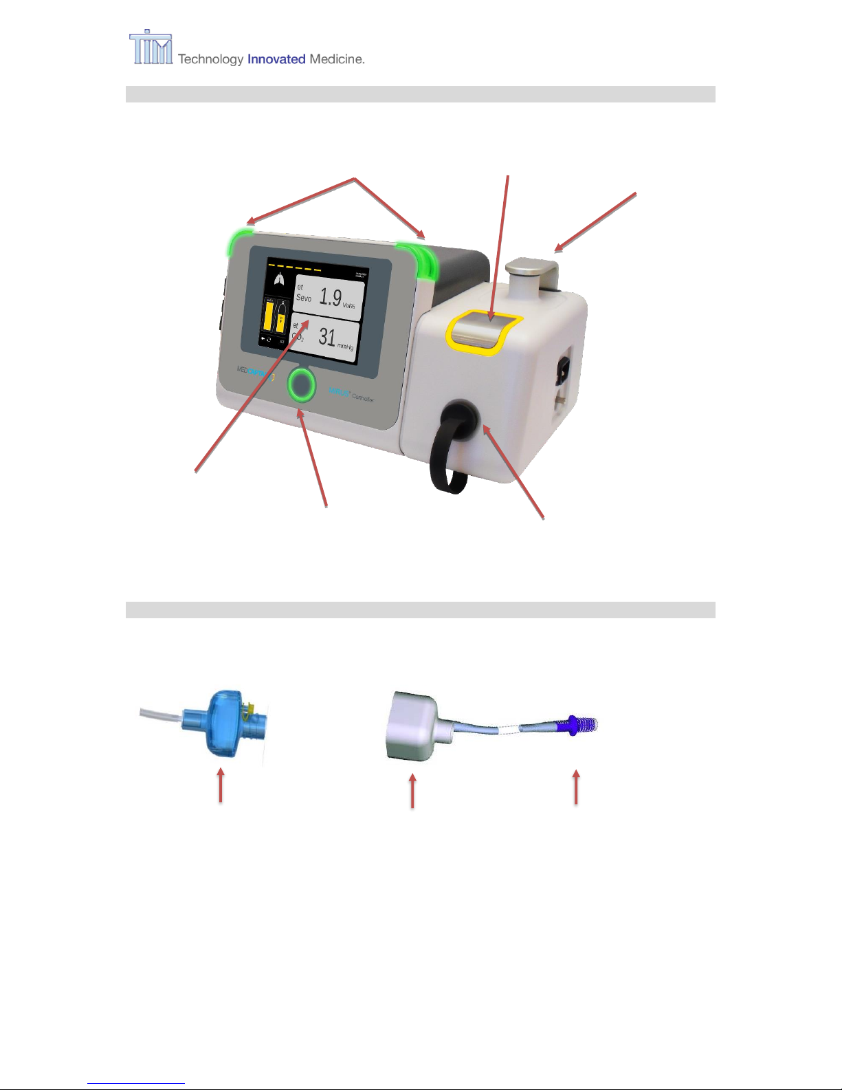
1.4.1 MIRUS Controller
1.4.2 Exchanger unit
Interface receptacle
Alarm lights
Fill port
Park Bay
Confirm button
Touch screen
MIRUS Reflector
(Multi patient device.
Use up to 7 days)
MIRUS Filter
(Single patient device.
Use up to 48 h)
Interface connector
Page 8
1 Introduction
8 IFU, MIRUS Controller, en-GB, N.00
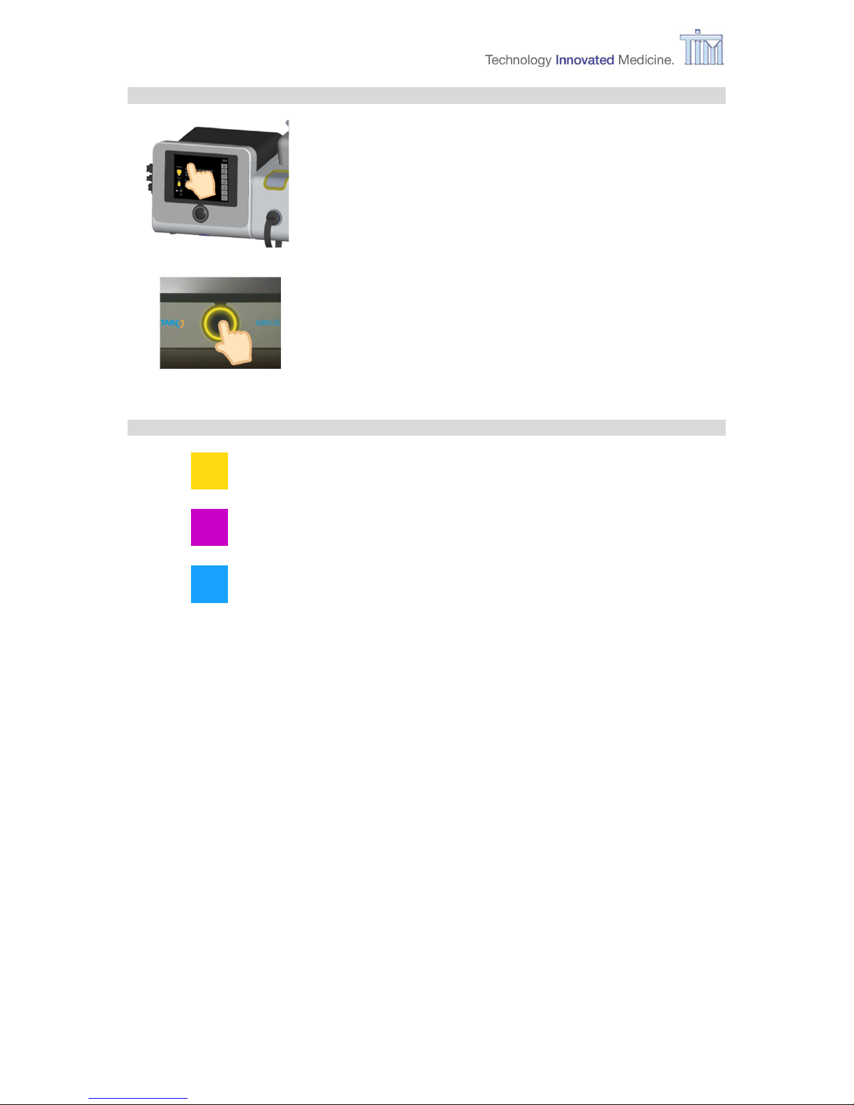
1.4.3 Device user interface
Touch screen.
Operate MIRUS Controller by pressing buttons on the graphical
user interface via touch sensitive screen.
Confirm button.
Confirm actions performed on the touch screen display by
pressing the Confirm button when flashing in anaesthetic colour
within 5 seconds.
1.4.4 Colour code for the different volatile anaesthetic agents (VA)
Colour for Sevoflurane
Colour for Isoflurane
Colour for Desflurane
Page 9

1 Introduction
IFU, MIRUS Controller, en-GB, N.00 9
1.4.5 Elements in touch screen
e.g. Home screen – standard operation screen
1
Status symbol Lung. Animated when patient breathing is detected.
2
Status symbol Life line. Animated when delivery is in progress, stationary when
delivery is paused. Not visible when delivery is stopped.
3
Display for et VA value
4
Display for et CO2 value
5
Menu button Home (Home screen for standard operation)
6
Menu button Patient data (gender, weight, size, age)
7
Menu button MAC Pilot (setting wash-in speed)
8
Menu button Respiratory monitoring (supervising respiratory patient data)
9
Menu button Alarm settings: change setting alarm limits
(et CO2 min, et CO2 max, et VA min, et VA max, Apnoe time, Alarm vol.)
10
Menu button Configurations:
Tab Filling (during operation)
Tab Setting (on-screen language, CO2 unit)
Tab Time setting (local time zone, time and date)
Tab Service (information about HW and SW version of MIRUS
Controller, contact details of the manufacturer)
1 3 4
5
7
9
11
12
13
15
17
20
21
18
2
22
19
16
14
10
8
6
Page 10
1 Introduction
10 IFU, MIRUS Controller, en-GB, N.00
11
Menu button Turn off (turn off device)
12
Button Stop: stops application of VA
13
Button MAC: displays unit and currently set value, setting MAC value.
14
Button Pause: pauses application of VA
15
Button Play: starts application of VA
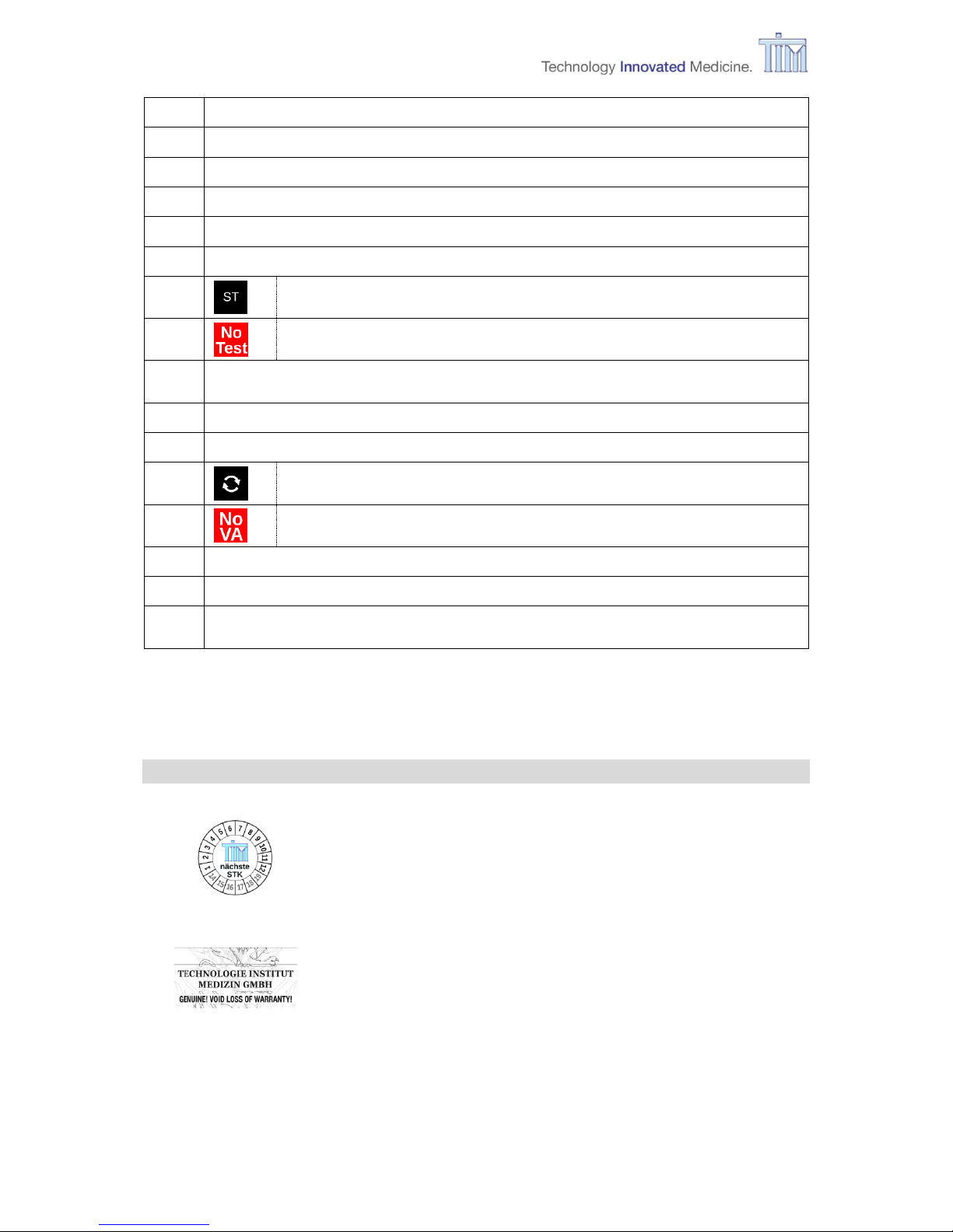
16
Status symbol System test.
ST. System test was performed successfully.
No Test. System test is invalidated.
17
Status symbol battery: Power supply via battery (with capacity indicator) or
battery is in charging mode (symbol is animated).
18
Status symbol mains supply: device is powered by mains supply.
19
Status symbol application of VA.
MAC pilot: MAC pilot active - VA is applied
(animated synchronously to lifeline)
NO VA: VA application not active (stop or pause).
20
Status symbol Agent reservoir: liquid level (in anaesthetic agent colour).
21
Graphic Target reached level: current Fi/Fe ratio.
22
Status symbol Reflector: remaining allowed operation time (in anaesthetic agent
colour).
Note: For more information about further symbols used on screens please refer to this IFU
and to the Additional Information (AI) of MIRUS Controller chapter 1.3.
1.5 Symbols on the device
STK label (in Germany):
Indicates when the next safety check in accordance with §6
Medical Device Operator Ordinance (MPBetreibV) is required.
Warranty seal:
Warranty void if seal is broken.
Note: For more information about further symbols used on the equipment please refer to the
Additional Information (AI) of MIRUS Controller chapter 1.3.
Page 11

2 Safety
IFU, MIRUS Controller, en-GB, N.00 11
2 Safety
2.1 General safety instructions
2.1.1 Safe operation
To ensure safe operation of the MIRUS Controller, use the system only as intended. Operators
need to be familiar with these Instructions for use (IFU) prior to operating the system. Only
trained operators should use this system. Always ensure compliance with the requirements of
this IFU and with the local governmental or other authority’s requirements.
2.1.2 User qualification
The MIRUS Controller should be operated by or on the order of a physician. The MIRUS
Controller should only be operated by qualified medical personnel, to ensure adequate
intervention in case of a device malfunction.
2.1.3 Monitoring
The MIRUS Controller is equipped with monitoring functions that will help to observe the device
situation and thereby serve to indicate changes in the parameters.
Changes in the parameters can be caused by:
changes in the status of the patient
changes in the settings
adjustment and/or operation failures
defects and/or device malfunction
changes in the power supply
changes in the anaesthetic supply
An alternative for patient sedation should be present to maintain sedation in case of a device
malfunction.
2.1.4 Electrical supply
The MIRUS Controller is built for AC supply with electrical power from a line supply voltage of
100 to 230 V
AC
± 10%, 50 to 60 Hz ± 5%. Verify your local AC line supply voltage matches the
rated device’s voltage on the serial plate.
The MIRUS Controller is equipped with an internal backup battery (UPS battery) that provides
a defined time of operation with reduced functionality upon loss of electrical mains supply
during application (refer to chapter 10.1 General specifications). This backup battery will
automatically switch on, whenever mains supply is lost. A symbol on the display appears to
inform the user.
Note: The device should only be stored with a fully charged battery.
Page 12
2 Safety
12 IFU, MIRUS Controller, en-GB, N.00
2.1.5 Responsibility of the manufacturer
The manufacturer is not responsible for any functional change of the device, damage or injury
to patient or operator that is caused by misuse or by disregard of the safety advice given in
this instruction for use.
The user or owner is responsible for the proper operation of the system, if the device is
serviced, maintained or repaired by unauthorised personnel.
The user or owner is responsible for the proper operation of the system if the device is misused
or not used according to the instructions given in these instructions for use.
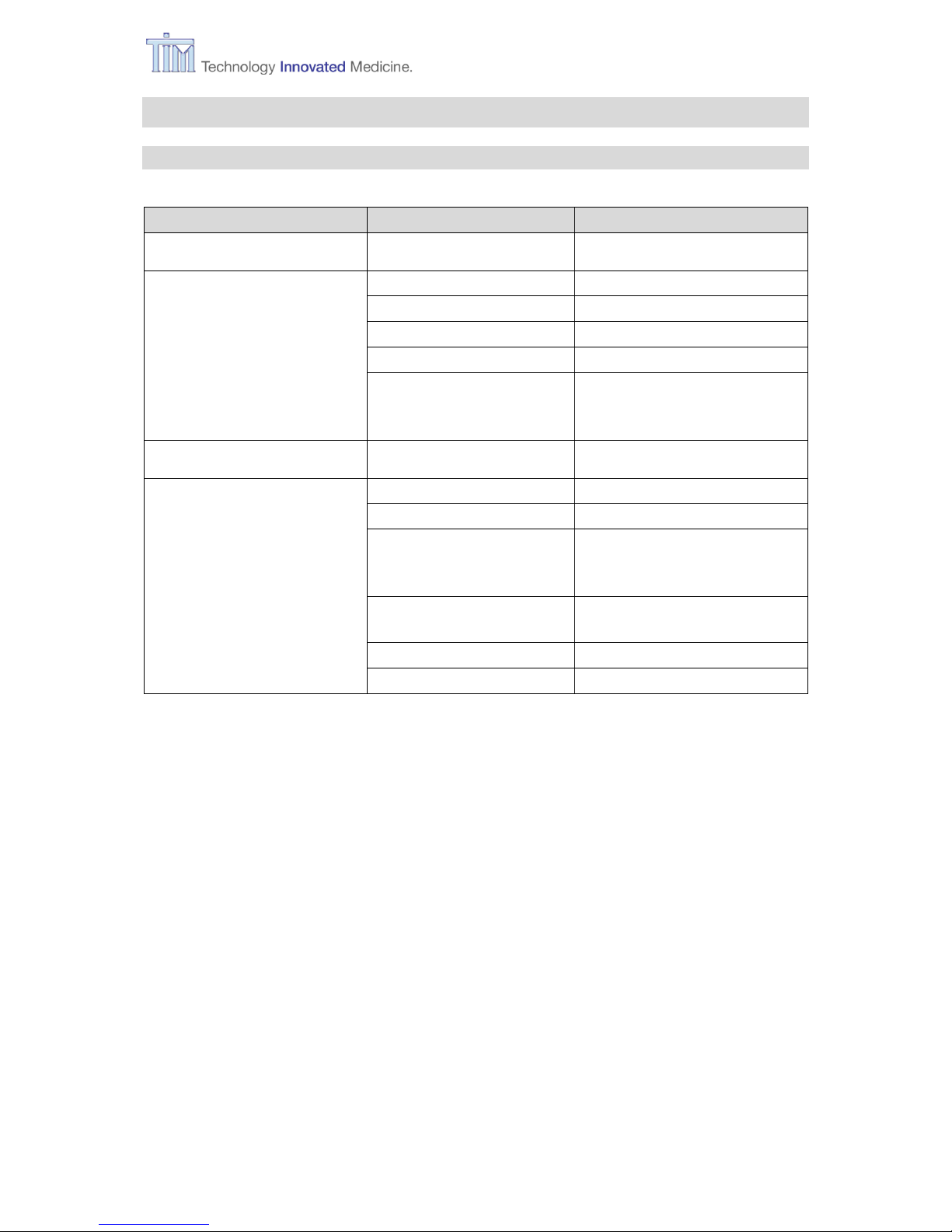
2.1.6 Safety features
The following safety features are built into the MIRUS Controller to warn the operator in case
of hazard to the patient.
Device alarms
Control of
Control for
Anaesthetic supply
Internal reservoir empty, Dosage failure
Electrical energy
Line supply fail, battery supply fail
Device’s control system
Watchdog alarm, Device inclined
Interface control
Occlusion or disconnection of Interface
MIRUS Reflector control
MIRUS Reflector expiration time
CAUTION The MIRUS Reflector control is only valid for a continuous connection
between MIRUS Interface plug and a powered MIRUS Controller (AC
connected). A disconnection of the plug or power off of the MIRUS
Controller will reset the timer.
Patient alarms
Control of
Control for
Anaesthetic concentration
Low and High et Sevo / et Iso / et Des
CO2 concentration
Low and High et CO2
Apnoea
Apnoea alarm
Page 13
2 Safety
IFU, MIRUS Controller, en-GB, N.00 13
2.2 Warning symbols used in the IFU
Caution
Not following this point will lead to damages to the device or the
system.
Warning
Not following this point will lead to patient and/or user harm.
2.3 Patient safety
2.3.1 Monitoring
WARNING For patient safety always use patient cardiovascular monitoring during
operation of the MIRUS System.
Do not use the MIRUS System for spontaneous breathing patients
without an apnoea backup ventilation safety mode.
For patient safety always perform a System test prior to operation.
In case of a non-functioning touch screen always disable the delivery
of anaesthetic by disconnecting the MIRUS Reflector Interface plug.
Always set alarm levels for et VA and et CO2 according to application
and patient.
2.3.2 Volatile anaesthetic agents (VA)
WARNING Using any other volatile anaesthetic agent than the one your MIRUS
Controller is designed for can result in overdosing and serious patient
injury.
Never use any bypass to the keyed filler system. This can result in
overdosing and serious patient injury.
Do not switch type of volatile anaesthetic agent while treating a patient.
Page 14
2 Safety
14 IFU, MIRUS Controller, en-GB, N.00
2.3.3 Control of patient relevant dosage
WARNING Always control the dosing of the volatile anaesthetic agent by
measuring the dose relevant end-expiratory agent concentration
(et VA).
Do not deliver any additional volatile anaesthetic agent to a breathing
system that is connected to the MIRUS System.
2.3.4 Combination of ventilators and MIRUS System
WARNING Use the MIRUS System only in combination with TIM tested ventilators
(see list of compatible ventilators).
Using the MIRUS System with ventilators that are not according to
ISO 80601-2-12 or ISO 80601-2-13 could endanger the patient.
Do not use the MIRUS System with jet or high frequency ventilators.
Do not use the MIRUS System with a helmet or face mask ventilation
(NIV).
2.3.5 Triggering of ventilators
WARNING When having placed the MIRUS System into the patient’s breathing
system ensure adequate triggering of the ventilator and readjust
triggering parameter, if necessary.
2.3.6 Minimum tidal volume
WARNING Do not use the MIRUS System at ventilation settings requiring
inspiratory tidal volumes < 300 mL.
Do not use the MIRUS System with additional breathing filters (HME/F)
at the y-piece or at the tube connection.
Do not use tubes etc. that significantly increase dead space.
Page 15
2 Safety
IFU, MIRUS Controller, en-GB, N.00 15
2.3.7 MDI Applications
WARNING Using MDI applications with the MIRUS System can result in an
underdosage of the patient for a short period of time.
2.3.8 Resistance of airway components
WARNING Never use an active humidification system when operating the MIRUS
System. This may result in serious increase of airway resistance.
When using the MIRUS System with an anaesthesia workstation,
never adjust the fresh gas setting to low-flow values (< 1.5 x MV). The
CO2 absorption process in the rebreathing circuit may generate heat
and moisture. This may result in serious increase of airway resistance.
Always monitor for possible increase in airway resistance.
2.4 User’s and other patient’s safety
WARNING You will work with volatile anaesthetic agents. To protect yourself and
others, observe the volatile anaesthetic agent manufacturer’s safety
instructions for handling with volatile anaesthetic agents.
Turn off volatile anaesthetic agent delivery when disconnecting the
patient’s breathing system to avoid ambient pollution.
Do not use the MIRUS System in parallel to extracorporeal membrane
oxygenation (ECMO) or extracorporeal membrane decarboxylation
(ECOR).
2.5 Device
2.5.1 Accessories
WARNING Use only accessories approved by the manufacturer of either the
MIRUS Controller or the accessory.
Page 16

2 Safety
16 IFU, MIRUS Controller, en-GB, N.00
2.5.2 Positioning
WARNING Never use the MIRUS Controller when not in a horizontal position to
avoid the liquid agent entering the gas pathway.
If the MIRUS Controller has tipped over, wait for a minimum of
10 seconds to ensure no liquid is in gas pathways before applying
anaesthetic agent.
Ensure the MIRUS Controller is always in a stable position.
2.5.3 Risk of electrical hazard
CAUTION Use the enclosed original line supply cable only.
Make sure, that the device is not covered by any material (e.g. a
curtain) during the operation. This may interfere with the device’s
cooling system.
Operate the system only according to the given specification for
temperature and humidity. In case the system's temperature is higher
or lower than specified, allow the system to stabilise in the specified
operation temperature for one hour before operation.
Do not use the MIRUS System for intra or inner clinical transport.
Do not use the MIRUS System in an emergency / ambulance car.
Do not use the MIRUS System in a helicopter or airplane.
2.5.4 Risk of fire
CAUTION Do not use materials such as Ammonium, Phenol, or Acetone to clean
the device.
Do not use the MIRUS Controller when there is doubt in the proper
function of the electrical earth ground in the installation environment.
Do not use the MIRUS Controller in the presence of flammable
anaesthetics.
Page 17

2 Safety
IFU, MIRUS Controller, en-GB, N.00 17
2.5.5 Electromagnetic compatibility
CAUTION Do not use the MIRUS System in the presence of an MRI System.
WARNING The use of other electrical equipment, e.g. the line supply cable, may
cause a higher EM-emission or may weaken the immunity of the
device. This may cause a risk to the patient.
The use of other electrical equipment on or near this system may cause
interference. Verify normal operation of equipment in your
configuration before connecting a patient.
2.6 Residual risk – Fail-safe mode
During its operation, the MIRUS Controller is monitored by a separate safety system. In case
of a failure, the safety system shifts the device to a fail-safe mode, which is safe for the patient.
During the fail-safe mode there is no delivery of anaesthetic to the patient.
Safe mode means:
screen is blank
no volatile anaesthetic agent is
delivered
alarm lights are flashing in red
confirm button is flashing in red
audible alarm sound
To silence the audible alarm, press the Confirm button for at least 4 seconds. MIRUS
Controller now turns off flashing red LEDs and stops alarm sound. To turn off the fail-safe
mode disconnect mains supply and press the Confirm button again for at least 4 seconds. The
red LEDs now turn off.
To restart MIRUS Controller after a fail-safe mode
wait for 5 seconds,
reconnect AC supply,
re-start by pressing the Confirm button (usual start).
Page 18
3 Preparation
18 IFU, MIRUS Controller, en-GB, N.00
3 Preparation
3.1 Cleaning before first use
The MIRUS Controller does not come sterilised; the device has to be cleaned completely by
the user before it is used clinically for the first time.
Refer to chapter 6.2 Cleaning for more information.
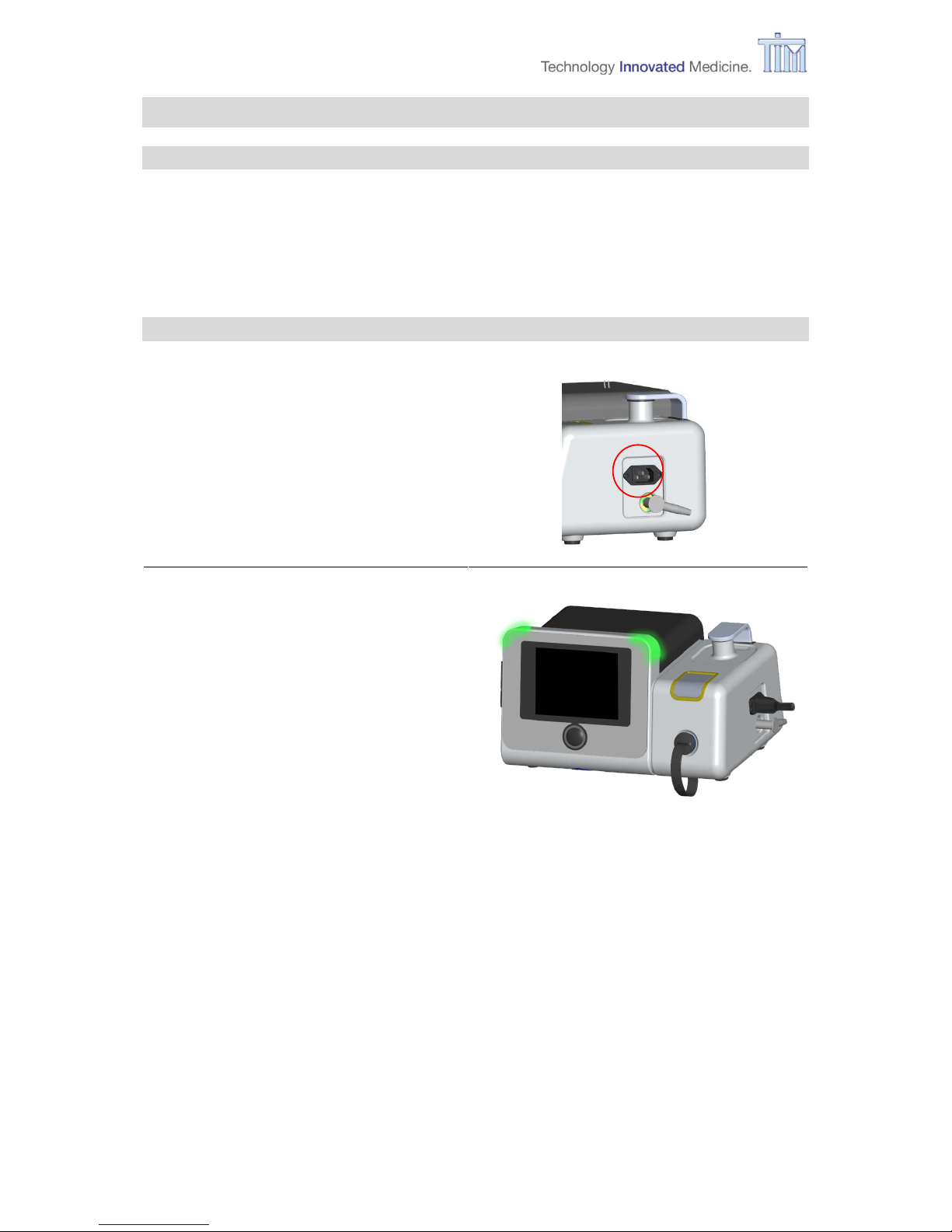
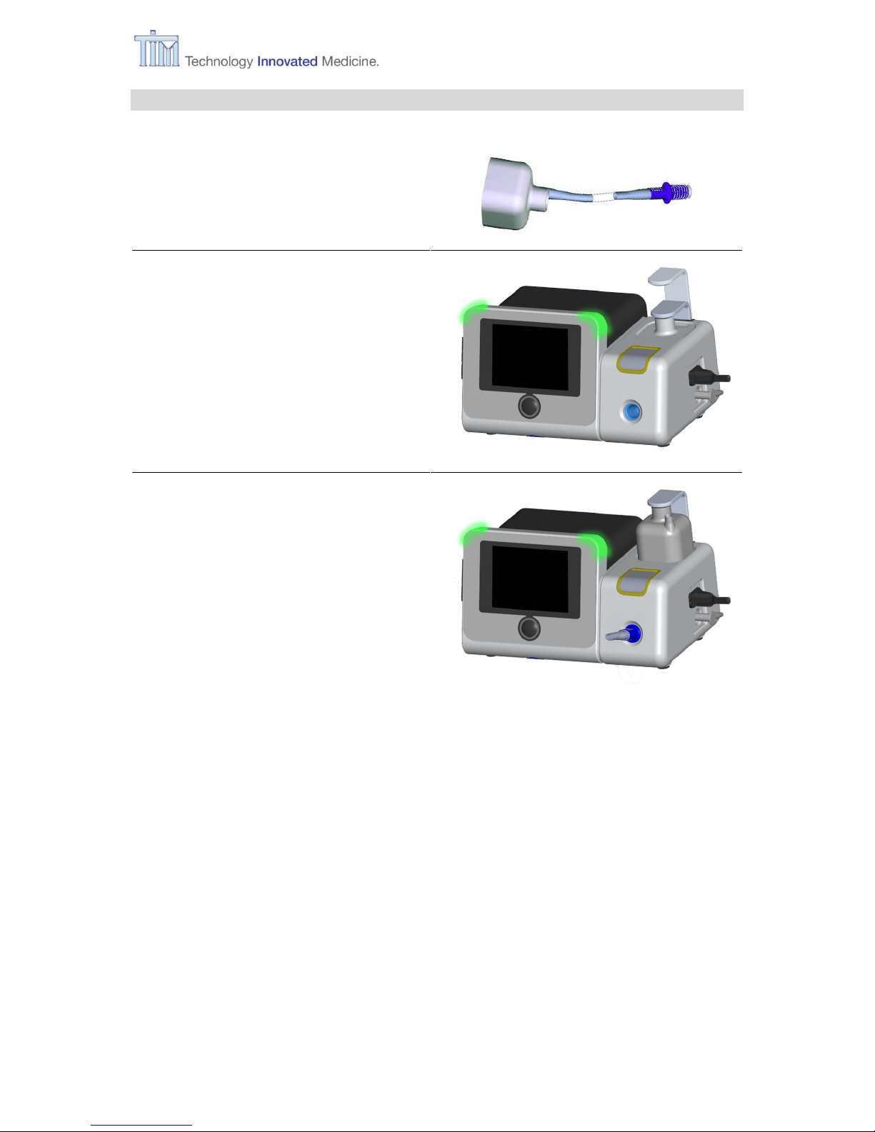
3.2 Connecting to mains supply
Plug in power cable into the inlet on the
right side of the Controller.
Connect to AC supply.
100 to 230 VAC ± 10%, 50 to 60 Hz ± 5%.
Alarm lights turn on in green.
(lights pulsate= battery charges)
Controller heats up.
Page 19
3 Preparation
IFU, MIRUS Controller, en-GB, N.00 19
3.3 Connecting to MIRUS Reflector
Remove the MIRUS Reflector with
interface plug from its packaging.
Note: For further information refer to the
manufacturer’s instructions.
Remove plug from interface connector
receptacle.
Lift Park Bay clip
Place Reflector.
Insert interface plug into plug receptacle.
Ready to turn on.
Page 20
3 Preparation
20 IFU, MIRUS Controller, en-GB, N.00
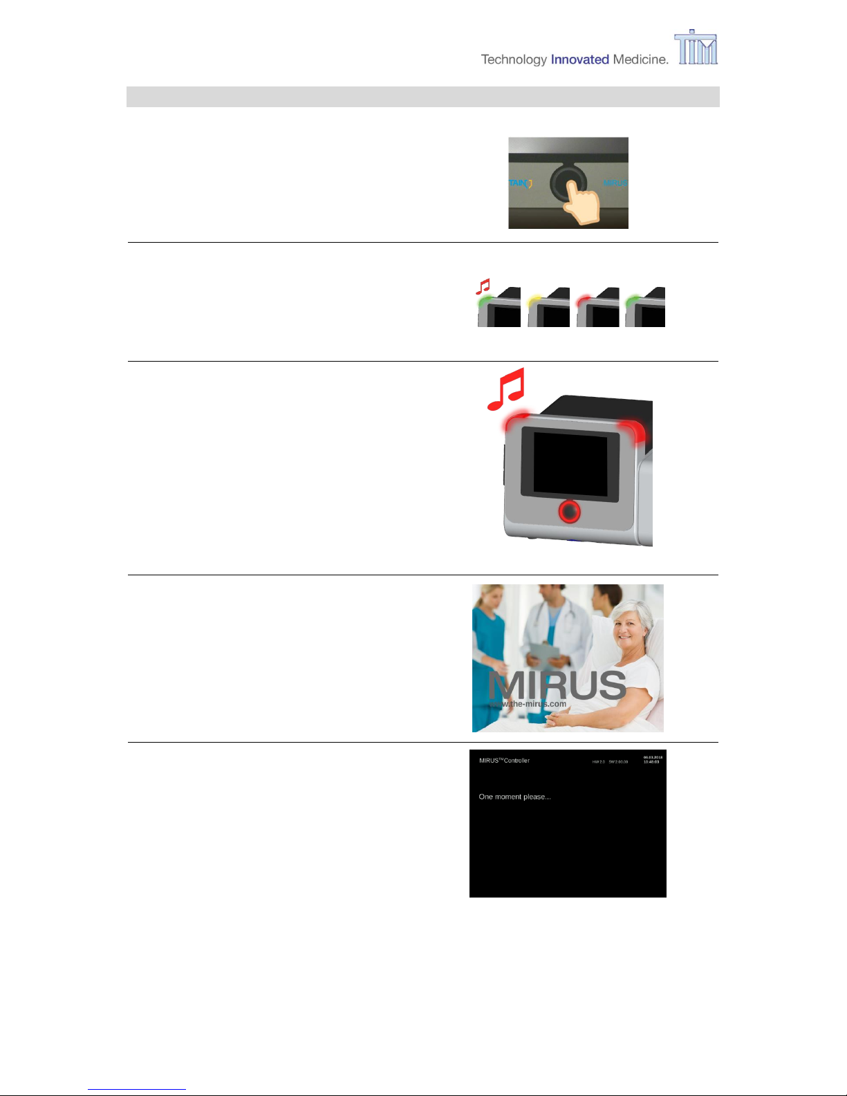
3.4 Turning on
Press Confirm button.
Start-up sound
Alarm lights flash in sequence red,
yellow and green for visual control.
Test fail-safe mode
Confirm button and alarm lights flash in
red for approx. 3 seconds. Panic alarm
sound is heard.
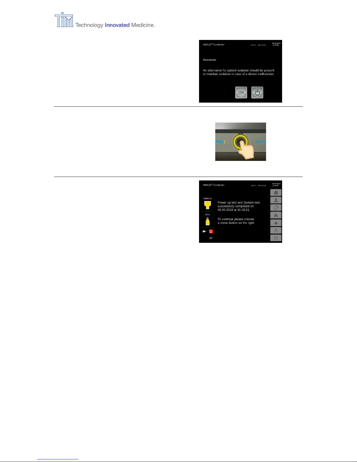
Initial screen
Power up test and system test
If a problem or an error occurs, follow the
instructions on the screen
Refer to chapter 7.2 Messages and error
messages for more information.
Page 21
3 Preparation
IFU, MIRUS Controller, en-GB, N.00 21
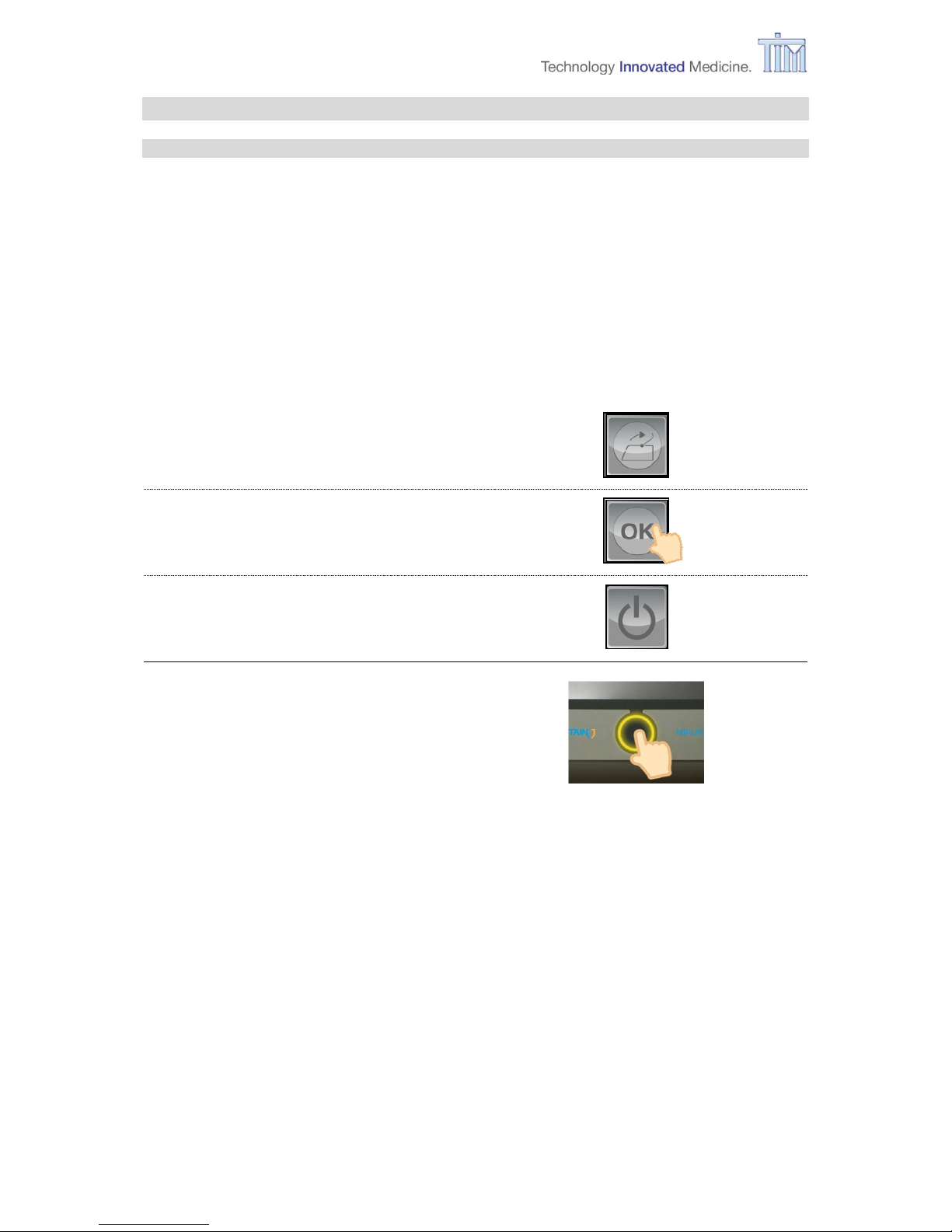
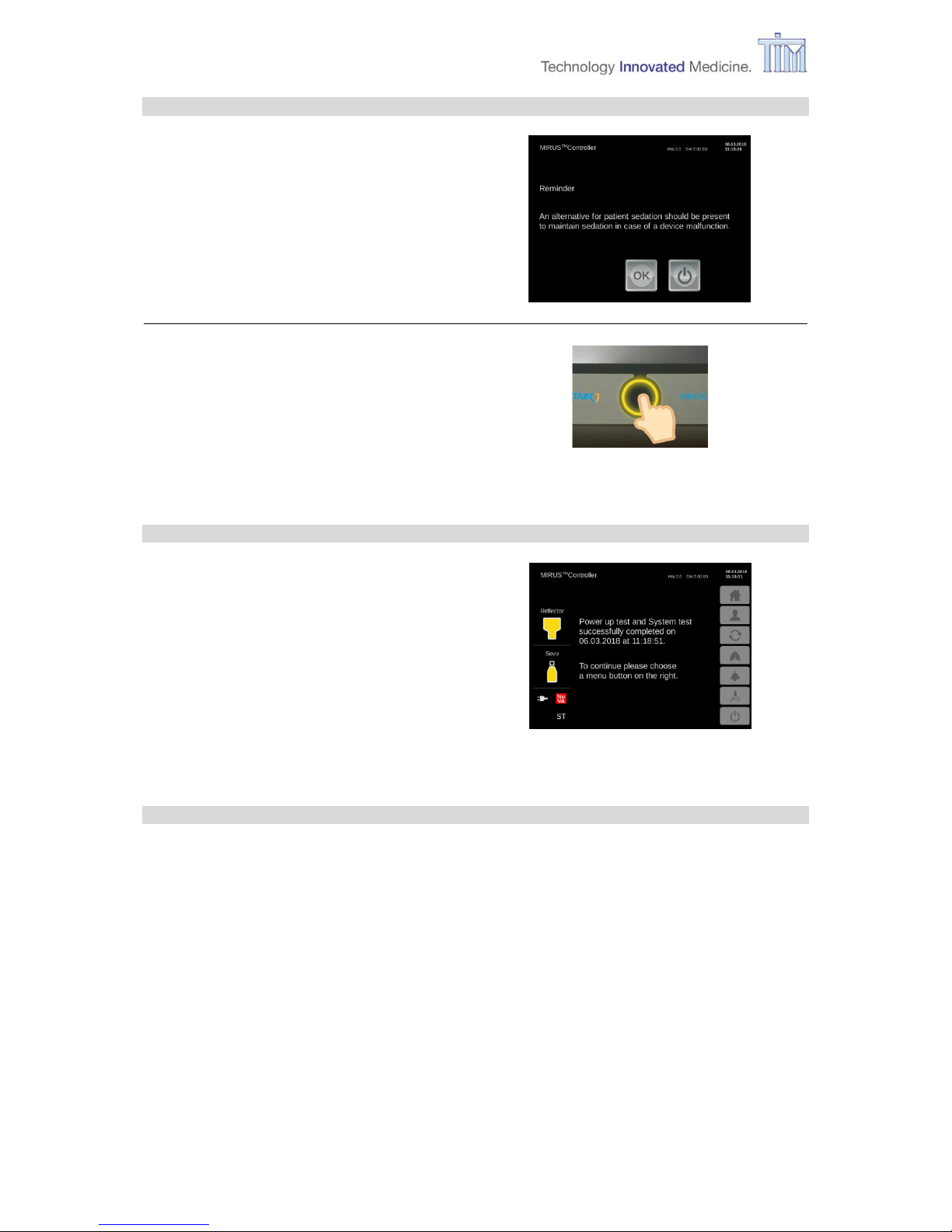
Reminder screen
Press OK to confirm.
Press Confirm button.
On-Call mode
Controller is ready for use.
To continue press one of the menu buttons on the right:
Home (standard mode)
(refer to chapter 3.7)
Patient data: gender, age, size, weight
(refer to chapter 3.8)
MAC-Pilot: Change wash-in speed
(refer to chapter 3.9)
Respiratory monitoring
(refer to chapter 4.2)
Alarm settings: Change values of alarm limits
(refer to chapter 3.10)
Configurations and filling: setting on-screen language, CO2 unit, Time zone, Date,
time. Filling during operation.
(refer to chapter 3.11)
Turn off
(refer to chapter 5)
Page 22
3 Preparation
22 IFU, MIRUS Controller, en-GB, N.00
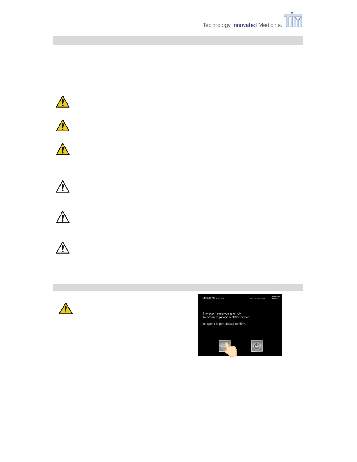
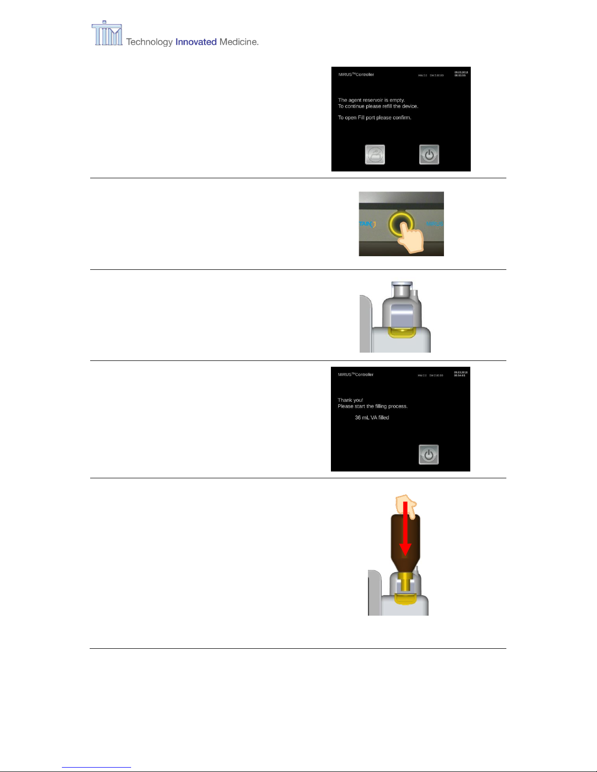
3.5 Filling during start-up sequence
If liquid volume level in reservoir is less than 75 mL, MIRUS Controller will require filling prior
to the system test. Wait for a request to fill (message on screen) and follow the instructions.
Note: For further information about the bottle adapter refer to the manufacturer's instructions.
CAUTION Only the suitable bottle adapter will match with MIRUS Controller.
CAUTION Don’t force an unsuitable adapter into the fill port.
CAUTION Double check bottle adapter colour, fill port collar colour and agent
bottle colour to match dedicated volatile anaesthetic agent prior to
filling.
WARNING Do not press the fill port valve manually down at any time. This will
result in pressure and vapour release.
WARNING Slowly remove bottle from fill port to reduce vapour pressure to avoid
ambient pollution.
WARNING Avoid spilling volatile anaesthetic agent during filling process to avoid
ambient pollution.
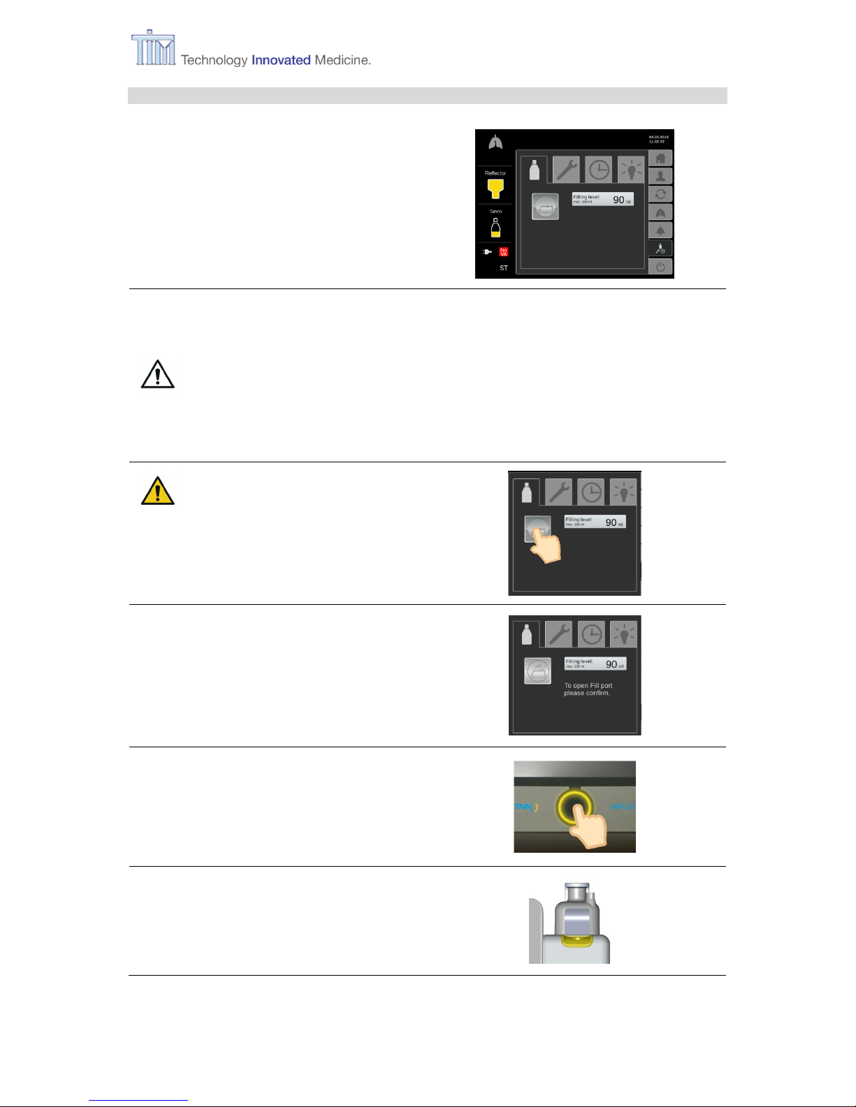
Perform
CAUTION Do not try to open the
flap manually, it could
be seriously damaged.
Press Fill port flap button to open fill port
flap or
press Turn off button to shut down device.
Page 23
3 Preparation
IFU, MIRUS Controller, en-GB, N.00 23
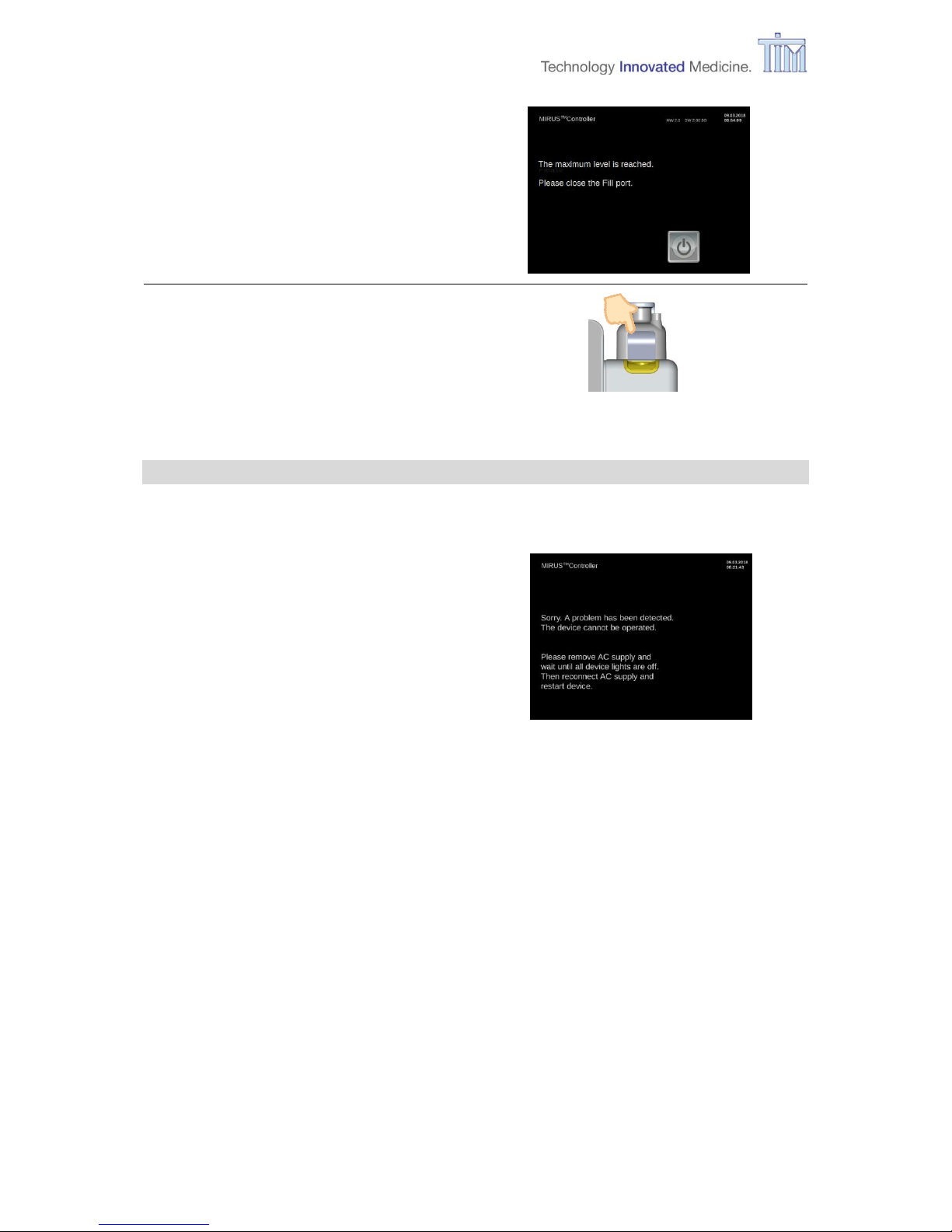
Button for fill port flap is light grey.
Press Confirm button.
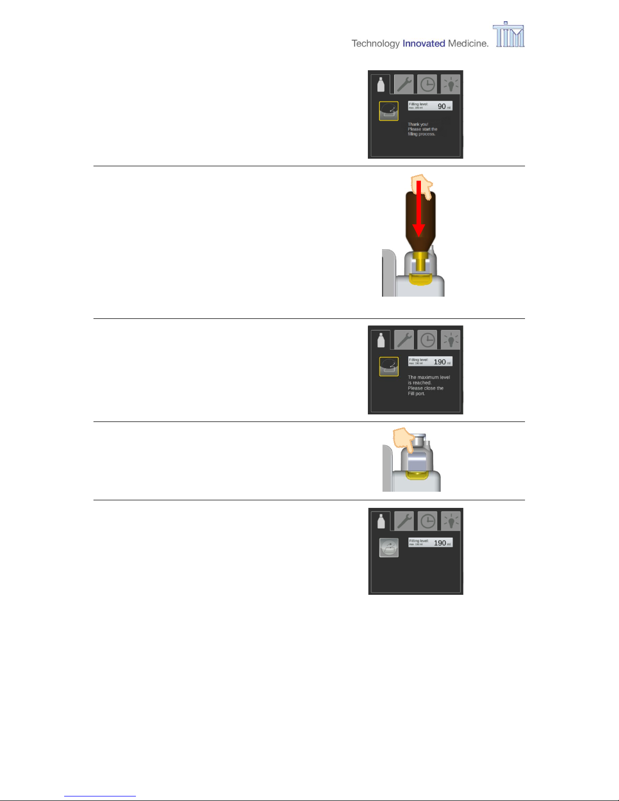
Fill port flap opens automatically.
Request for filling.
Filling:
Insert bottle with attached adapter
vertically in fill port.
Press bottle into fill port gently until a
mechanical stop is felt (spring
loaded valves open).
Reservoir is filled.
Note: Device cannot be overfilled.
Page 24
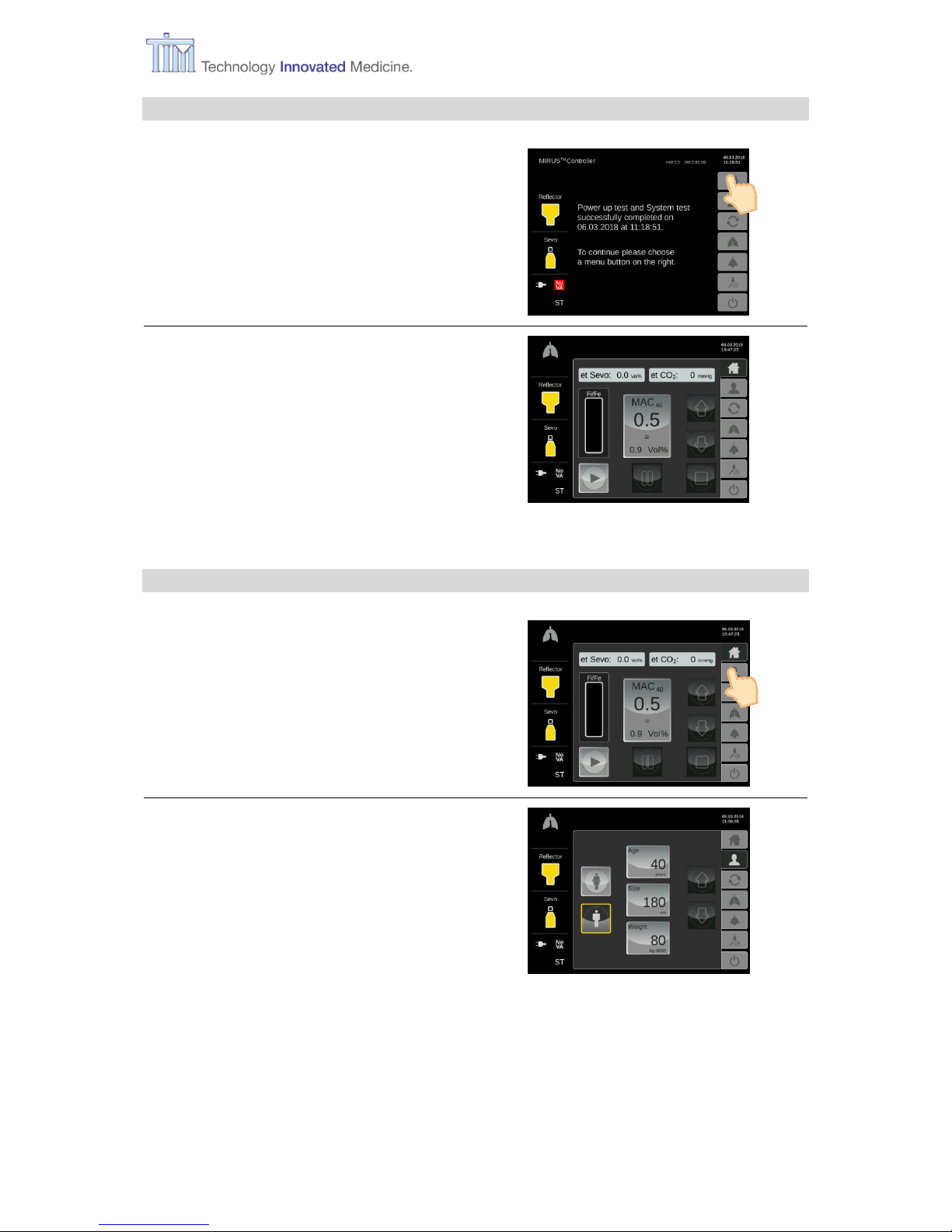
3 Preparation
24 IFU, MIRUS Controller, en-GB, N.00
Max. level reached
Remove bottle.
Close fill port flap.
Controller continues start-up sequence.
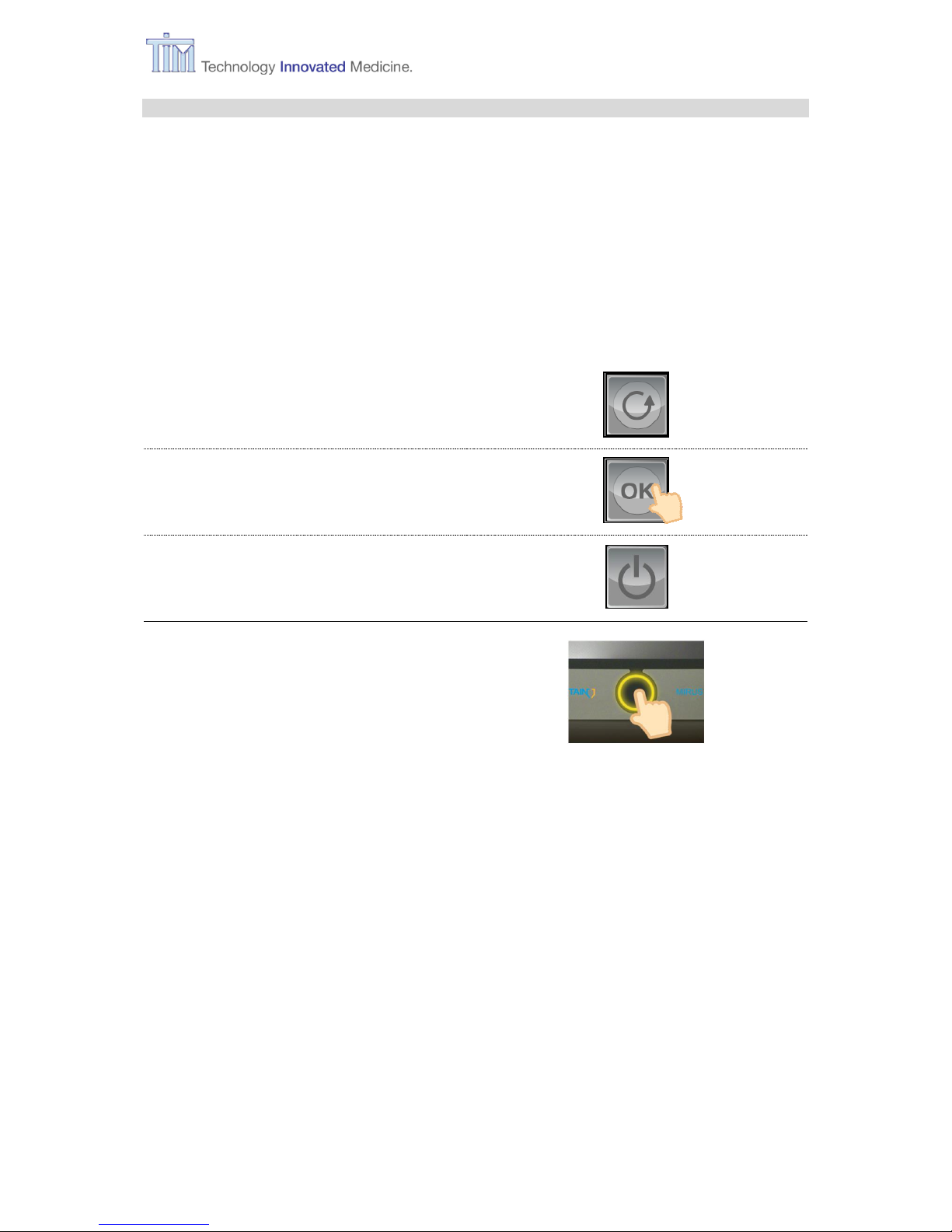
3.6 Anomaly in start-up sequence
In rare cases it can lead to an anomaly in start-up sequence.
To restart MIRUS Controller
disconnect AC supply,
wait for 5 seconds (green lights off),
reconnect AC supply,
restart by pressing the Confirm
button (usual start).
Page 25
3 Preparation
IFU, MIRUS Controller, en-GB, N.00 25
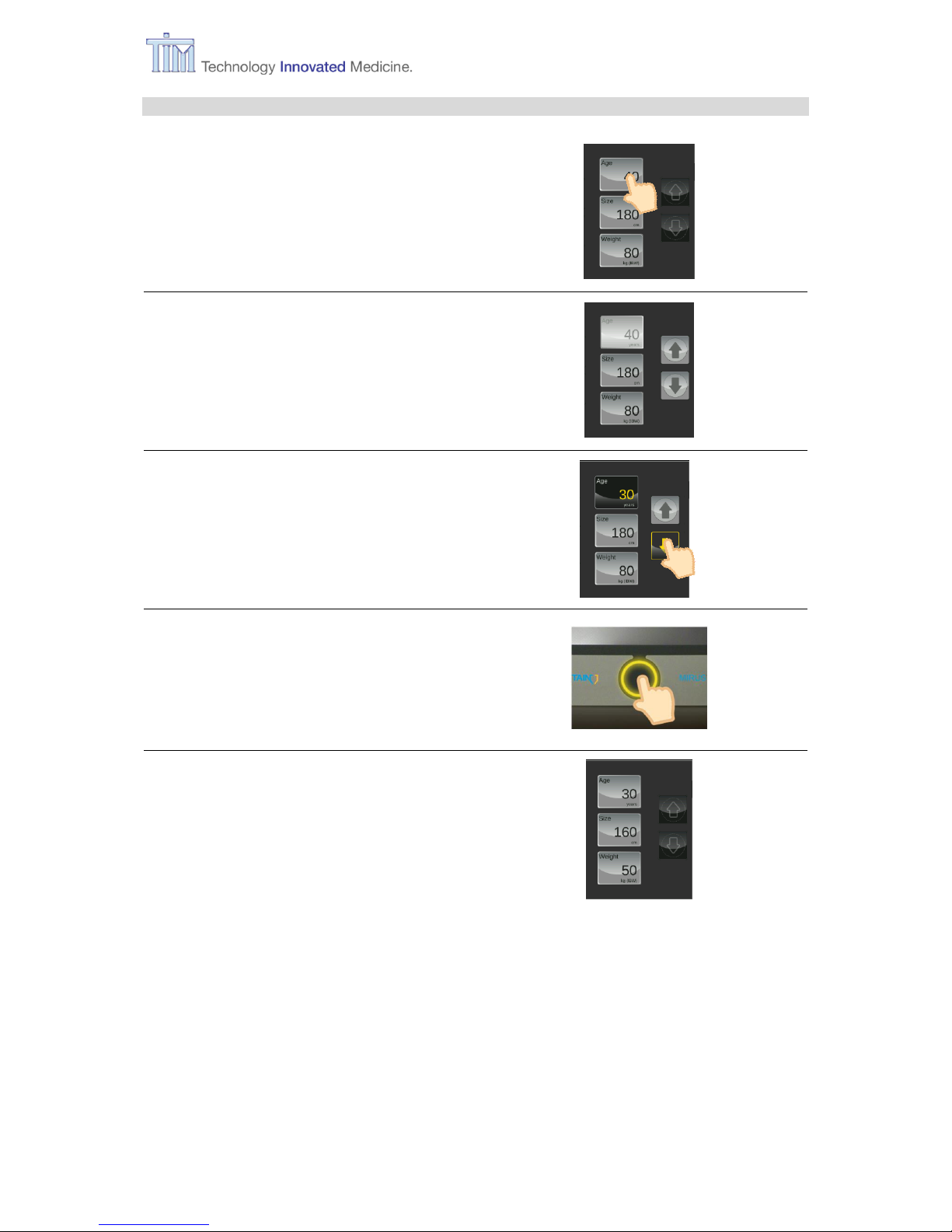
3.7 Change to operation mode
Press menu button Home.
Home screen
pre-set MAC value, e.g. SEVO
MAC
40
= 0.5 = 0.9 Vol%
Refer to chapter 8.1 Alarm settings and
application defaults for more information
about ISO and DES.
3.8 Changing patient data
Press menu button Patient data.
Note: Changing patient data is also
possible during VA application.
Patient data
pre-set:
gender: male
age: 40 years
size: 180 cm
weight: 80 kg
Page 26

3 Preparation
26 IFU, MIRUS Controller, en-GB, N.00
3.8.1 Changing gender
Press button for selected gender.
Button for selected gender is light grey.
Press Confirm button to verify change.
Change completed.
Page 27
3 Preparation
IFU, MIRUS Controller, en-GB, N.00 27
3.8.2 Changing age, size, weight
Press button for parameter to be changed,
e.g. age.
Button for selected parameter is light
grey.
Arrow keys are activated.
Use arrow keys to change parameter.
Press Confirm button.
Change completed.
Page 28

3 Preparation
28 IFU, MIRUS Controller, en-GB, N.00
3.9 Changing wash-in speed
Press menu button MAC pilot.
Note: Changing wash-in speed is also
possible during VA application.
MAC pilot
pre-set Wash-in speed:
rabbit = medium
Further options:
turtle = slow
cheetah = fast
Refer to chapter 8.2 Specification of wash-
in speed parameters for further information.
Press button for selected wash-in speed.
Button for selected wash-in speed is
light grey.
Press Confirm button.
Change completed.
Page 29

3 Preparation
IFU, MIRUS Controller, en-GB, N.00 29
3.10 Changing alarm settings
Press menu button Alarm settings.
Note: Changing alarm settings is also
possible during application of VA.
Alarm settings
pre-set alarm limits for SEVO:
et CO2 min = 20 mmHg
et CO2 max = 50 mmHg
et SEVO min = 0.5 Vol%
et SEVO max = 2.5 Vol%
Apnoe time = 60 sec
Alarm vol. = 100 %
Refer to chapter 10.2.2 Alarm settings for
information about ISO and DES.
Press button for parameter to be changed,
e.g. et CO2 max.
Button for selected parameter is light
grey.
Arrow keys are activated.
Use arrow keys to change parameter.
Page 30

3 Preparation
30 IFU, MIRUS Controller, en-GB, N.00
Press Confirm button.
Change completed.
3.11 Filling and additional configurations
Press menu button Configuration
screens.
Note: Configuration is also possible
during VA application.
Options
1st tab: filling-screen
2nd tab: setting language, CO2 unit
3rd tab: setting time zone, date, time
4th tab: service screen
Page 31
3 Preparation
IFU, MIRUS Controller, en-GB, N.00 31
3.11.1 Filling during operation
Filling-tab
Filling VA reservoir.
Note: Filling is also possible during
VA application.
Note: During application of VA, VA delivery is maintained during filling process, as long as
internal pressure is sufficient.
WARNING Always control the et VA concentration of the patient during filling as
it might decrease.
Note: Observe the warnings in chapter 3.5 Filling during start-up.
CAUTION Do not try to open the
flap manually, it could
be seriously damaged.
Press Fill port flap button.
Button Fill port flap is light grey.
Follow instruction on screen.
Press Confirm button.
Fill port flap opens automatically.
Page 32
3 Preparation
32 IFU, MIRUS Controller, en-GB, N.00
Fill port flap open.
Filling:
Insert bottle with attached adapter
vertically in fill port.
Press bottle into fill port gently until a
mechanical stop is felt (spring
loaded valves open).
Note: Device cannot be overfilled.
Maximum level reached.
Follow instruction on screen.
Close fill port flap.
Fill port flap closed.
Reservoir filled.
Page 33
3 Preparation
IFU, MIRUS Controller, en-GB, N.00 33
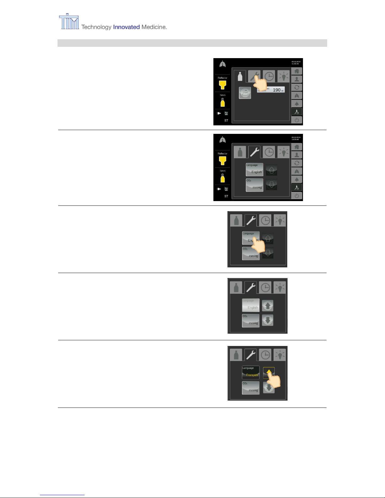
3.11.2 Setting on-screen language and CO2 unit
Select tab for Setting
Setting
Setting on-screen language and CO2 unit
pre-set:
Language = English
CO2 unit = mmHg
Press button for parameter to be changed,
e.g. language.
Button for selected parameter is light
grey.
Arrow keys are activated.
Use arrow keys to change parameter.
Page 34
3 Preparation
34 IFU, MIRUS Controller, en-GB, N.00
Press Confirm button.
Change completed.
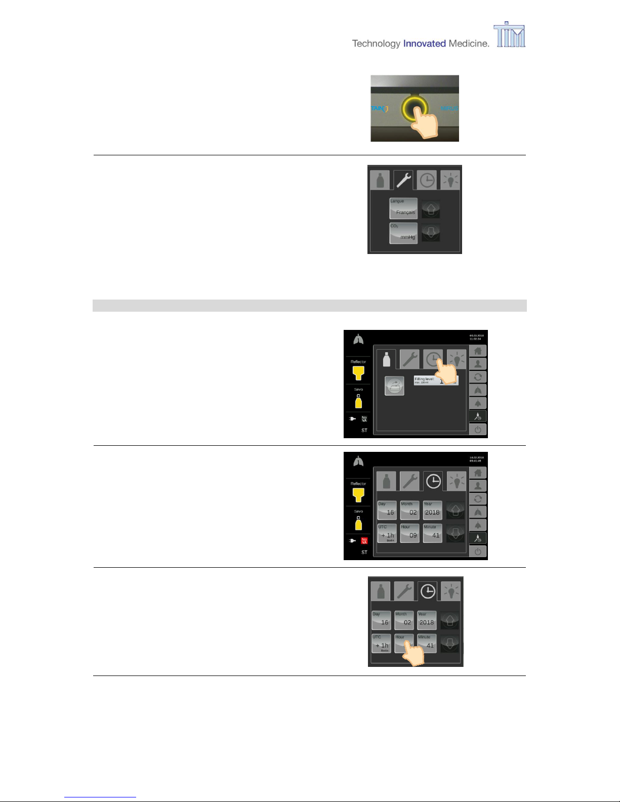
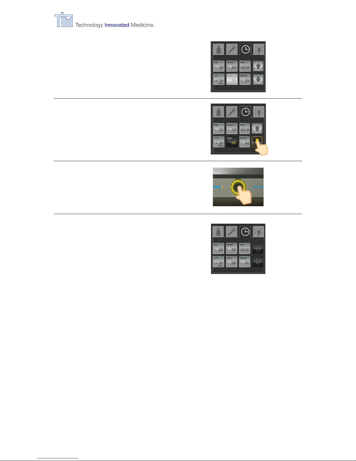
3.11.3 Setting time
Select tab for Time setting
Time setting
Setting Time zone, date and time
Pre-set:
Time zone = UTC +1h
Note: Check time zone setting and
correct first if necessary.
Press button for parameter to be changed,
e.g. hour.
Page 35
3 Preparation
IFU, MIRUS Controller, en-GB, N.00 35
Button for selected parameter is light
grey.
Arrow keys are activated.
Use arrow keys to change parameter.
Press Confirm button.
Change completed.
Page 36
3 Preparation
36 IFU, MIRUS Controller, en-GB, N.00
3.11.4 Service screen
Select tab for Service
Service screen
Information about SW and HW revision, the
web-contact and a QR code.
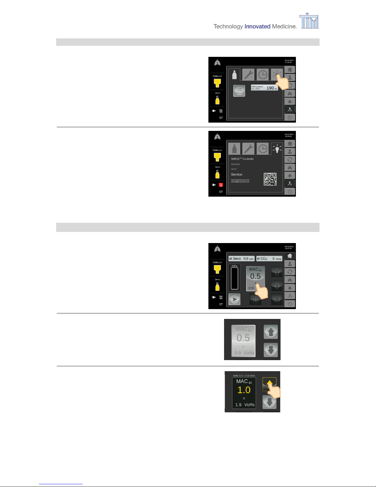
3.12 Setting MAC value (Vol%)
Operation mode.
Press button MAC.
Button for MAC is light grey.
Arrow keys are activated.
Use arrow keys to change MAC value.
Page 37
3 Preparation
IFU, MIRUS Controller, en-GB, N.00 37
Press Confirm button.
Change completed.
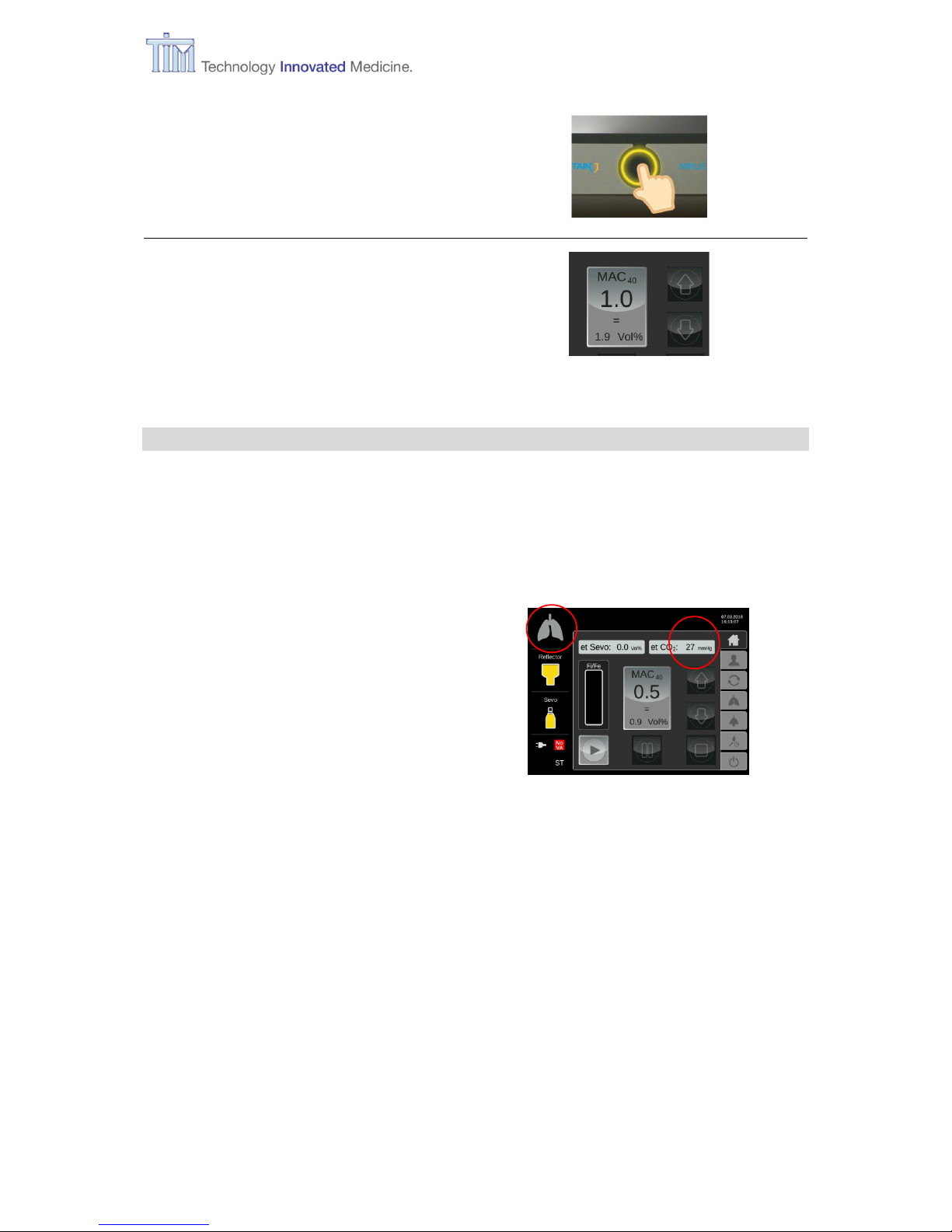
3.13 Connecting patient
In order to connect the patient to the device you need a filter in addition to the reflector already
connected to the controller (refer to chapter 1.4.2 Exchanger unit).
Note: For information regarding the reflector and the filter and how to connect these
accessories with the patient and the controller please refer to the manufacturer’s
instructions for use (IFU).
When the patient is connected to the
controller, the lung icon is animated and the
controller measures an et CO2 value.
Page 38
4 Application of VA
38 IFU, MIRUS Controller, en-GB, N.00
4 Application of VA
The following activities are all done on the Home screen (operation mode).
Home screen
(Operation mode)
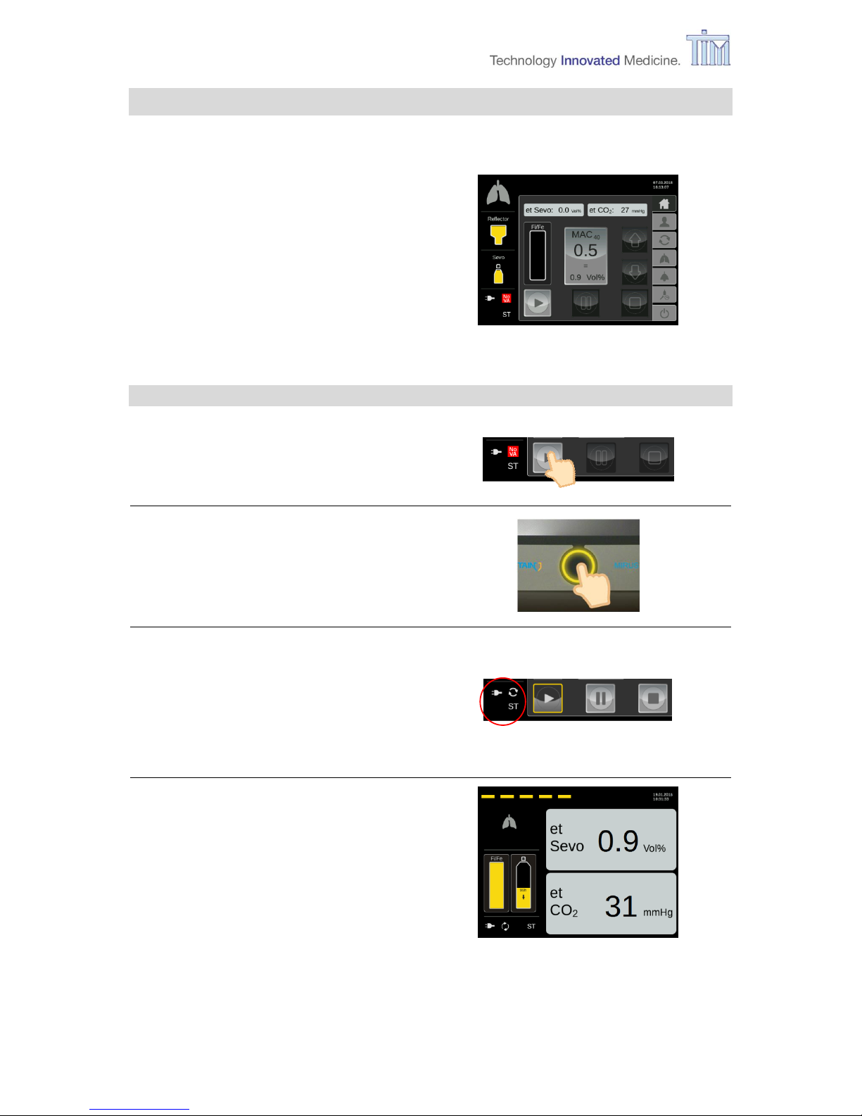
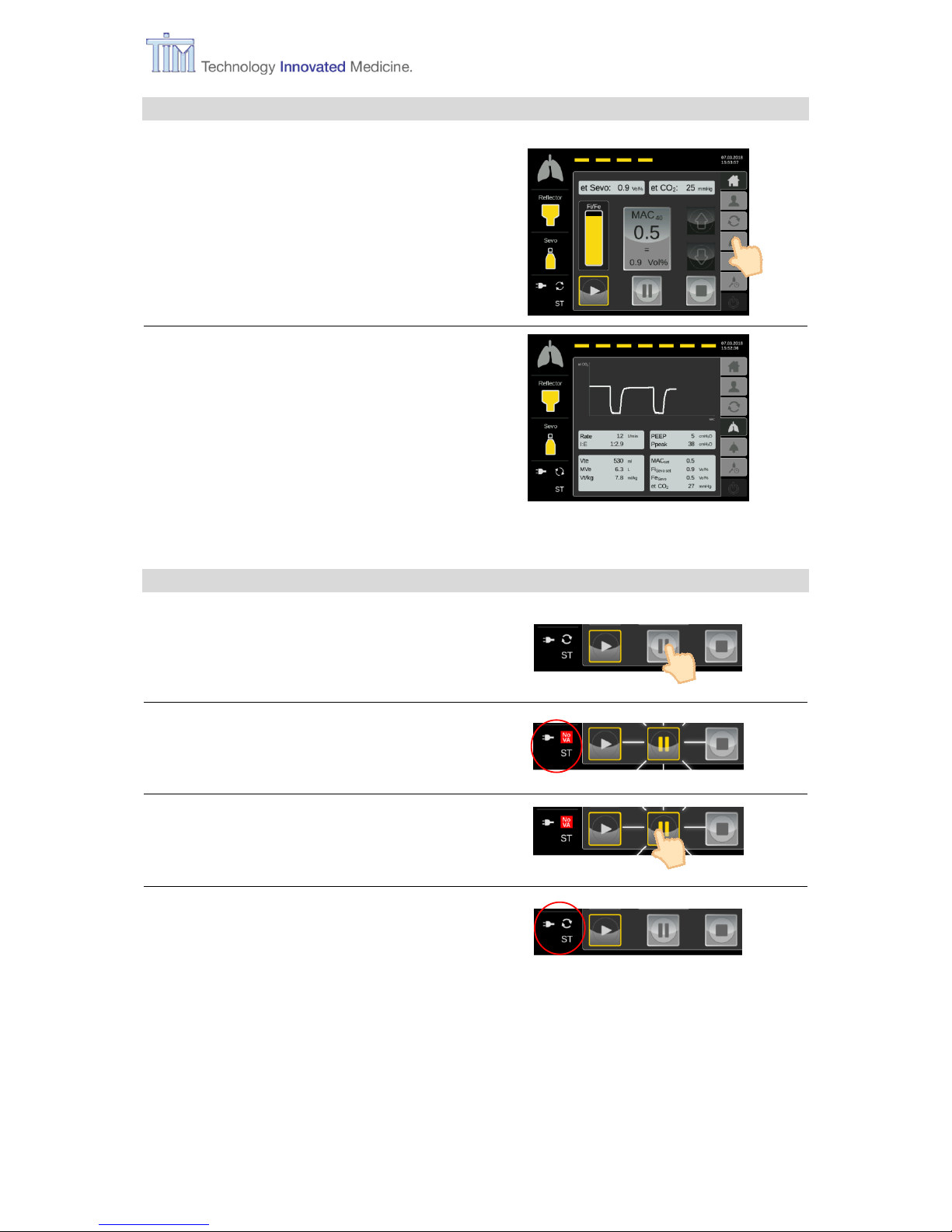
4.1 Starting application
Press button Start.
Press Confirm button.
VA Application active.
Animated life line at the top of the
screen (see next picture). MAC Pilot
status symbol is active.
Pause and Stop buttons activated.
After 10 minutes of no activity on the
touch screen, the controller switches to
snooze screen.
Note: After touching screen, controller
switches back to Home screen.
Page 39
4 Application of VA
IFU, MIRUS Controller, en-GB, N.00 39
4.2 Supervise patient respiratory data
Press menu button Respiratory
monitoring.
Respiratory monitoring screen
4.3 Pausing application and reactivate
Press button Pause.
VA Application pauses.
Button Pause flashes.
Press button Pause.
VA Application active again.
Page 40
4 Application of VA
40 IFU, MIRUS Controller, en-GB, N.00
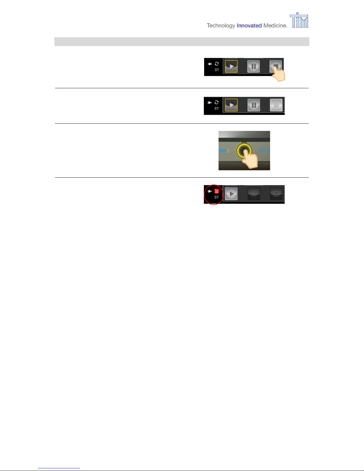
4.4 Stopping application
Press button Stop.
Button Stop is light grey.
Press Confirm button.
VA Application is finished.
Pause and Stop buttons deactivated.
Page 41
5 Turning off
IFU, MIRUS Controller, en-GB, N.00 41
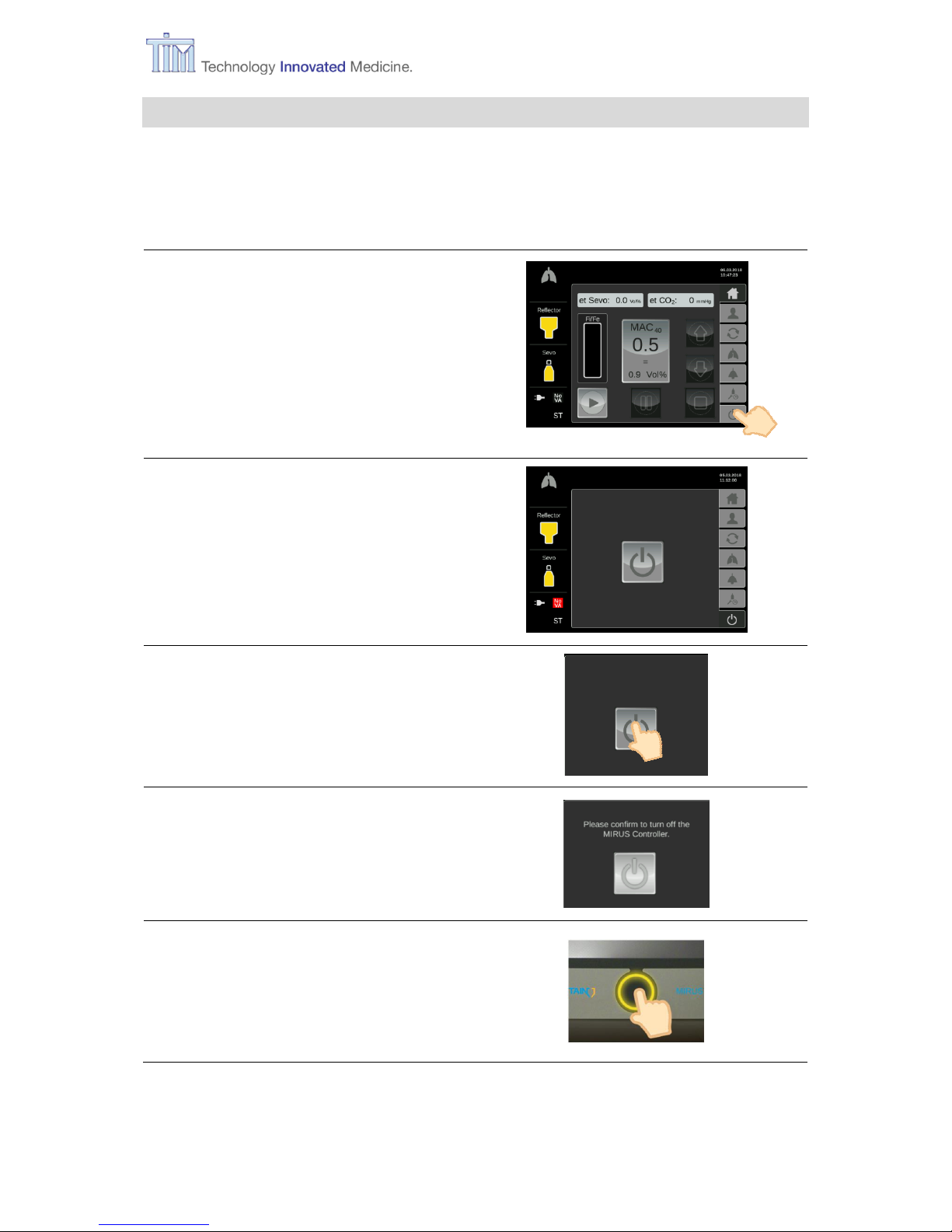
5 Turning off
Note: Only if VA is not applied, the menu button Turn off is activated.
Refer to chapter 4.4 Stopping application .
Press menu button Turn off.
Turn off screen
Press button Turn off.
Button Turn off is light grey.
Press Confirm button.
Page 42

5 Turning off
42 IFU, MIRUS Controller, en-GB, N.00
Button Turn off is coloured.
Controller switches off automatically.
Place Reflector in Park Bay.
Controller switched off (off mode).
Page 43

6 Maintenance and Cleaning
IFU, MIRUS Controller, en-GB, N.00 43
6 Maintenance and Cleaning
6.1 Maintenance
6.1.1 General Information
Maintenance, safety checks and maintenance measures must be performed only by the
manufacturer or by qualified personnel authorized by the manufacturer.
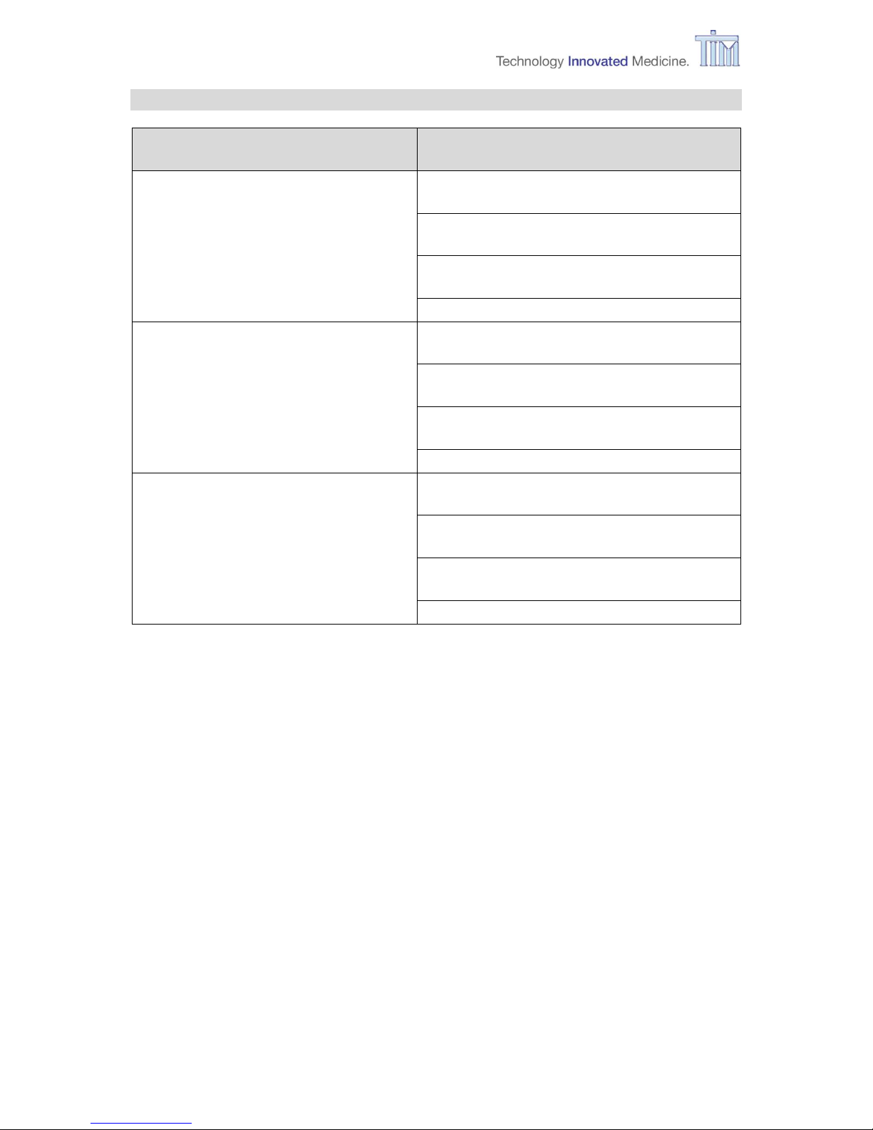
6.1.2 Schedule
Affected part
Period
Performer
MIRUS Controller
Every 12 months Safety Check
Visual Inspection
Electrical Safety Test
Checking gas monitor
Checking pump
Safety Function test
Manufacturer or qualified
personnel specially
authorized by the
manufacturer
UPS Battery pack
When not using the device, leave
device connected to mains supply or
connect to mains supply at least once
a month for at least 24h.
Replace every 2 years.
Manufacturer or qualified
personnel specially
authorized by the
manufacturer
Fan filter
Replace every 12 months.
Manufacturer or qualified
personnel specially
authorized by the
manufacturer
VA reservoir
Empty every 4 weeks.
Do not re-use VA.
User / Operator
Software
Manufacturer gives information as
soon as software update is available.
Manufacturer or qualified
personnel specially
authorized by the
manufacturer
Page 44

6 Maintenance and Cleaning
44 IFU, MIRUS Controller, en-GB, N.00
6.2 Cleaning
6.2.1 General advice
WARNING Observe the following safety precautions:
Read the material data sheet for each cleaning agent.
Wear gloves and safety glasses.
Do not breathe the fumes.
CAUTION To prevent damage:
Refer to the manufacturer’s data if you have questions about a
cleaning agent.
Do not use organic, halogenated or petroleum based solvents,
anaesthetic agents, glass cleaner, acetone or harsh cleaning
agents.
Do not use abrasive cleaning agents, such as steel wool, silver
polish or silver cleaner.
Keep all liquids away from electrical parts.
Do not permit liquids to go into the equipment’s housing.
Do not autoclave any part of the MIRUS Controller.
No part of the MIRUS Controller is sterilisable.
WARNING To prevent patient contamination:
Follow general hygiene requirements of your hospital.
Do not re-use single use components.
6.2.2 Cleaning the individual components
MIRUS Controller surface
a. Turn off the MIRUS Controller and ensure that the mains power cord is
disconnected.
b. Make sure the fill port is closed.
c. Remove MIRUS Reflector and interface plug.
d. Make sure the receptacle token is placed in the MIRUS Reflector receptacle and
the receptacle is sealed.
e. Make sure the three connector tokens are placed in the communication ports and
the ports are sealed.
f. Use a soft towel to clean the housing, the display and the user interface. When
using fluid cleaner, use a mild detergent and do not permit liquids to penetrate the
housing.
Page 45

6 Maintenance and Cleaning
IFU, MIRUS Controller, en-GB, N.00 45
For wipe disinfection use agents with the following ingredients:
Agent
Specification
Alcohol based
Containing:
Isopropyl alcohol (70% solution)
Ethyl alcohol (70% solution)
Composition of Ethyl alcohol (70%) and
Isopropyl alcohol (70%)
Non-alcohol based
Containing quaternary ammonium compounds:
Didecyldimethylammoniumchloride
max. 0,25 g / 100 g ready-for-use solution
Alkyl(C12-16)dimethylbenzylammoniumchloride
max. 0,5 g / 100 g ready-for-use solution
For wipe disinfection TIM recommends:
Bacillol® Wipes
Dr. Schumacher® Cleanisept Wipes
Terralin® protect
In addition to the main ingredients, cleaning agents and disinfectants often contain additives
which can damage the materials. If in doubt, contact the supplier/manufacturer of the
disinfectant/detergent.
List of materials used:
Component
Material
Housing
Polystyrene (PS)
Alarm lights
Polycarbonate (PC)
Touch Screen
Polyester (PES)
Park Bay
AlMgSi alloy, anodised, AlCuMg, anodised
Fill port Flap
AlMgSi alloy, anodised
Seals / Covers
Silicone, Polyethylene (PE), Synthetic rubber (EPDM)
Battery flap
Aluminium, anodised
Screws
Stainless steel
Labels
Polyethylene (PE)
Housing feet
Polyvinylchloride (PVC)
Fan filter
Acrylonitrile butadiene styrene (ABS)
Power supply cord
Acrylonitrile butadiene styrene (ABS), Polyvinylchloride (PVC)
IEC plug
Polybutylene terephthalate (PBT)
Potential equalization
Nickel-plated brass
Page 46

6 Maintenance and Cleaning
46 IFU, MIRUS Controller, en-GB, N.00
WARNING Ensure that the housing and the touch screen have dried completely
before reconnecting the MIRUS Controller to an electrical supply.
MIRUS Controller Fill port
Always keep the fill port flap closed to avoid the entry of dust or other substances. In case
the fill port needs to be cleaned use a clean and lint free cloth. Avoid using cotton swabs as
they too will leave small particles and lint in the fill port.
MIRUS Reflector
To clean the external surfaces of the MIRUS Reflector follow the instructions for use supplied
with the product.
MIRUS Filter
The MIRUS Filter is a single use device and should not be soaked, rinsed, washed, sterilised
or treated with liquid disinfectants.
6.3 Draining the reservoir
To drain the reservoir, a draining kit from the manufacturer TIM is needed (refer to chapter
9 Parts list for ordering information). Perform the draining according to the manufacturer’s
guide that comes with the draining kit.
6.4 Shipping MIRUS Controller
If the MIRUS Controller is to be sent, it must be cleaned and disinfected (refer to chapter
6.2 Cleaning), as well as completely emptied (refer to chapter 6.3 Draining the reservoir).
Only use the original packing material to pack the MIRUS Controller:
Safety bag
Transport jacket (top and bottom frame)
MIRUS Controller box white
MIRUS Controller shipping box, 2-piece
If the original packing material is not available, it can be ordered via:
service@tim-products.de
Perform the packing as described in the manufacturer’s guide.
Page 47

7 Alarms and messages
IFU, MIRUS Controller, en-GB, N.00 47
7 Alarms and messages
7.1 Alarms
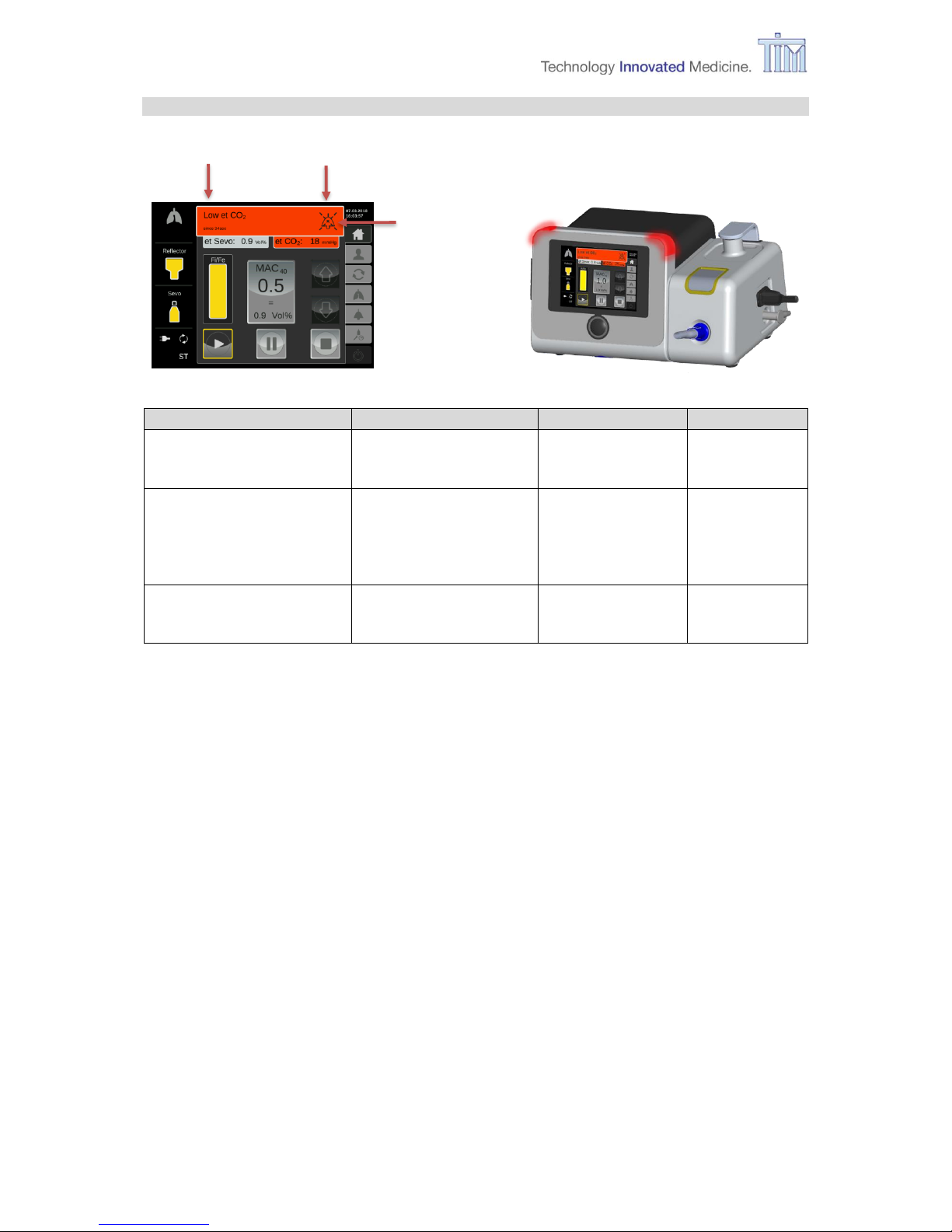
7.1.1 Alarm modality
The MIRUS Controller distinguishes between high- and low-priority alarms. Alarms only occur
during operation and are shown in the following way:
Alarm lights: red or yellow alarm lights activated
On screen: red or yellow alarm bar with text, red or yellow highlighted icon
Audible alarm: alarm sound
Note: The alarm volume will escalate from 50% sound intensity up to the set volume (max.
100%) until alarm is muted.
If there is another alarm after the first alarm, the second alarm bar overlays the first alarm bar.
Exception: if the further alarm is a low-priority alarm, the alarm bar of the high-priority alarm
remains visible. The highlighted icons (if present by the alarms) are both recognizable.
7.1.2 Low-priority alarms
Activity
Screen
Alarm light
Audible alarm
Alarm is active.
Alarm message
yellow continuous
ON
Confirming the
alarm by activating
the alarm silence
button.
Alarm message
yellow, continuous
OFF
Alarm bar
Silence button
No highlighted
icon in this
example.
Page 48
7 Alarms and messages
48 IFU, MIRUS Controller, en-GB, N.00
7.1.3 High-priority alarms
Activity
Screen
Alarm light
Audible alarm
Alarm is active
Alarm message
Start timer
red, flashing
ON
Confirming the alarm by
pressing the alarm silence
button
Alarm message
Start silence counter
(2 min).
red, continuous
OFF
Alarm is still active after the
“2 min” silence time
Alarm message
Timer
red, flashing
ON
Alarm bar
Silence button
highlighted icon
Page 49
7 Alarms and messages
IFU, MIRUS Controller, en-GB, N.00 49
7.1.4 Patient alarms
Alarm
(in alphabetical
order)
Priority
Device
action
Set condition
Reset condition
Apnoea
Low
Alarm and
stop VA
delivery
No breathing activity.
Breathing activity
detected.
High et CO
2
High
Alarm
Measured et CO2 >
max et CO2 for three
consecutive breaths.
Measured et CO2 within
the limit with the first
breath.
High et VA
VA = Sevo, Iso
or Des
High
Alarm
Measured et VA >
max etVA for three
consecutive breaths.
Measured et VA within
the limit with the first
breath.
Low et CO
2
High
Alarm
Measured et CO2 <
min et CO2 for three
consecutive breaths.
Measured et CO2 within
the limit with the first
breath.
Low et VA
VA = Sevo, Iso
or Des
High
Alarm
Measured et VA < min
et VA for three
consecutive breaths.
Measured et VA within
the limit with the first
breath.
Low Vt
High
Alarm
Measured Vti <
200 mL for five
consecutive breaths.
Measured Vti ≥ 200 mL
with the first breath.
High
Alarm and
stop VA
delivery
Measured Vti < 50 mL
for five consecutive
breaths.
Measured Vti ≥ 50 mL
with the first breath.
Page 50

7 Alarms and messages
50 IFU, MIRUS Controller, en-GB, N.00
7.1.5 Technical alarms
Alarm
(in alphabetical
order)
Priority
Device
action
Set condition
Reset condition by
user
Device
inclined.
Low
Alarm and
stop VA
delivery.
Tilt angle > 25° for
t < 30 sec.
Reposition device on
level surface.
High
Alarm and
stop VA
delivery.
Tilt angle > 25° for
t ≥ 30 sec.
Dosage
failed!
Start VA?
High
Alarm and
stop VA
delivery.
Calculation problem
was detected.
Restart VA delivery by
pressing Play and
confirm or turn off
device.
Failure! Turn
off.
High
Alarm and
stop VA
delivery.
A technical failure was
detected.
Turn off device.
Fill port flap
still open.
Low
Alarm
Fill port flap open
>5 min.
Close fill port flap.
High
Alarm
Fill port flap open
>7 min.
Heating
system failed.
High
Alarm
No activity of the
heating system could
be detected.
Turn off device.
Interface
disconnected.
High
Alarm and
stop VA
delivery.
Interface plug
disconnected while in
operation.
Reconnect interface
plug.
Mains supply
lost.
Low
Alarm
AC lost.
Connect mains supply.
Occlusion of
Interface
High
Alarm and
stop VA
delivery.
A gas sampling or
measurement line is
clocked.
Check interface for
kinking.
Check fresh gas flow of
AWS to be min 1.5 *
MV.
Overtemperature
Low
Alarm
Inner Controller
temperature > 55°C
Check fan input and
output.
Pause still
active.
Low
Alarm and
pause VA
delivery.
Delivery paused for >
2 min.
Neutralise interception
by pressing Pause.
Please
replace
Reflector
promptly!
Low
Alarm
No valid values from
Reflector.
Replace reflector.
(System test should be
repeated as soon as
possible.)
Reflector
expired.
Low
Alarm
Interface not released
for >160 hours.
Prepare to replace or
replace reflector.
Reflector
soon expires.
Low
Alarm
MIRUS Interface not
released for 144 –
160 hours.
Prepare to replace or
replace reflector.
Reservoir
needs refill
Low
Alarm
Internal reservoir fill
level < 60 mL
Refill reservoir.
Reservoir
empty
High
Alarm
Internal reservoir fill
level < 45 mL.
Refill reservoir.
Page 51

7 Alarms and messages
IFU, MIRUS Controller, en-GB, N.00 51
Alarm
(in alphabetical
order)
Priority
Device
action
Set condition
Reset condition by
user
Set date and
time!
Low
Alarm
When comparing the
internal clock with a
setpoint, a deviation
was detected (e.g.
after a long time
without power supply)
Correct date and time.
UPS battery
low
High
Alarm
if UPS battery is down
to ≤ ¼ of capacity
(2 minutes left).
Allow recharging of
UPS battery.
VA
application
not active.
Low
Alarm
Breathing activity
detected but VA
application is not
started by user via
Play.
Start VA application via
Play.
Page 52
7 Alarms and messages
52 IFU, MIRUS Controller, en-GB, N.00
7.2 Messages and error messages
7.2.1 During power up test
The following will be checked during power up test:
level reservoir
state of charge UPS battery
position of controller
connection to power supply
electronic components
If a problem or an error is detected, follow the instructions on the screen. Depending on the
instruction, one or more of the following buttons are available on the screen (after selecting
press Confirm button):
Fill Port Flap
OK Turn off
Press Confirm button.
Note: For more information, refer to Additional Information (AI) of MIRUS Controller chapter
7.4.1.
Page 53
7 Alarms and messages
IFU, MIRUS Controller, en-GB, N.00 53
7.2.2 During system test
The following will be checked during system test:
position of reflector
connection of interface plug
pneumatic components
position of controller
connection to power supply
If a problem or an error is detected, follow the instructions on the screen. Depending on the
instruction, one or more of the following buttons are available on the screen (after selecting
press Confirm button):
Repeat
OK
Turn off
Press Confirm button.
Note: For more information, refer Additional Information (AI) of MIRUS Controller chapter
7.4.2.
Page 54
7 Alarms and messages
54 IFU, MIRUS Controller, en-GB, N.00
7.2.3 Reminder screen
Verify that an alternative for patient sedation
is present.
Confirm by pressing OK or turn off device via
Turn off button.
Press Confirm button.
7.2.4 During On-Call mode
Follow request on screen.
7.2.5 During operation mode
During operation mode some user activity is required
when filling the reservoir.
when turning off the controller.
Follow instructions on screen.
Refer to chapter 3.11.1 Filling during operation and chapter 5 Turning off for more information.
Note: For more information, refer to Additional Information (AI) of MIRUS Controller chapter
7.4.5.
Page 55
8 Standard values
IFU, MIRUS Controller, en-GB, N.00 55
8 Standard values
8.1 Alarm settings and application defaults
Screen
Parameter
Default value
Home
MAC
0.5
Patient data
Gender
male
Age
40 years
Ideal body weight
80 kg
Body height
180 cm
Vol.
SEVO 0.9 Vol%
ISO 0.6 Vol%
DES 3.4 Vol%
MAC Pilot
Wash-in speed
medium
Alarm settings
et CO2 min
20 mmHg
et CO2 max
50 mmHg
et VA min
ISO 0.3 Vol %
SEVO 0.5 Vol %
DES 1.7 Vol%
et VA max
MAC * 2.0
(VA specific)
Apnoea time
60 seconds
Alarm volume
100%
Page 56
8 Standard values
56 IFU, MIRUS Controller, en-GB, N.00
8.2 Specification of wash-in speed parameters
Volatile Anaesthetic agent
Specification
Isoflurane
cheetah = Fast
2* set MAC-value
rabbit = Medium
1.5* set MAC-value
turtle = Slow
1.0* set MAC-value
max. concentration: 6 Vol%
Sevoflurane
cheetah = fast
2* set MAC
rabbit = medium
1.5* set MAC-value
turtle = slow
1.0* set MAC-value
max. concentration: 8 Vol%
Desflurane
cheetah = fast
1.5* set MAC-value
rabbit = medium
1.25* set MAC-value
turtle = slow
1.0* set MAC-value
max. concentration: 18 Vol%
Page 57
9 Parts list
IFU, MIRUS Controller, en-GB, N.00 57
9 Parts list
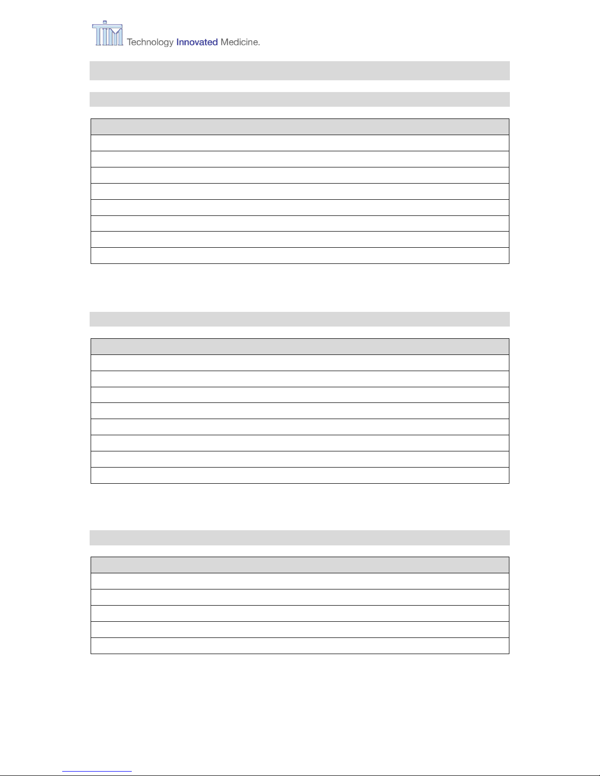
9.1 Accessories
Description Order code
Bottle adapter Sevofluran QUIK-FIL BA-SEV-Q
Bottle adapter Sevofluran BA-SEV-K
Bottle adapter Isofluran BA-ISO-K
Bottle adapter Desfluran SAF-T-FIL BA-DES-S
MIRUS Mounting Bracket - Base MC-01-014
MIRUS Mounting Bracket - VESA arm MC-01-014-1
MIRUS Mounting Bracket - Rail (2pcs.) MC-01-014-2
9.2 Spare parts
Description Order code
Power supply cable DE, ES MC-01-001
Power supply cable UK MC-01-002
Power supply cable FR MC-01-003
Power supply cable IT MC-01-004
Power supply cable CH MC-01-005
Power supply cable AU MC-01-006
UPS backup battery MC-01-011
9.3 Service parts
Description Order code
MIRUS Draining Kit MC-01-013
MIRUS Draining kit - Spare bottle MC-01-013-1
MIRUS Event Log µSD Card MC-01-016
MIRUS Replacement filter MC-09-905
MIRUS Data cable MC-SC-DC-01
Page 58

9 Parts list
58 IFU, MIRUS Controller, en-GB, N.00
9.4 Documents
Documents can be ordered as printed version or accessed online on the manufacturer’s
website: http://the-mirus.com/mirus-controller-instructions-for-use.html
Description Order code
MIRUS Controller Instruction for Use (en-GB, de, fr, it, es)
and Additional Information (en-GB) CD MC-MC-IFU-ALL
9.5 MIRUS Controller
Description Order code
MIRUS Controller Isoflurane MC-MC-ISO
MIRUS Controller Sevoflurane MC-MC-SEV
MIRUS Controller Desflurane MC-MC-DES
Page 59
10 Technical specifications
IFU, MIRUS Controller, en-GB, N.00 59
10 Technical specifications
10.1 General specifications
Specification
Device
Physical dimensions (L x H x D)
325 x 195 x 210 mm (12.8 x 7.6 x 8.2 in.)
Weight
with filled reservoir
9.0 kg (15.4 lb)
HW Options
MC-MC-ISO
MC-MC-SEVO
MC-MC-DES
For VA Isoflurane
For VA Sevoflurane
For VA Desflurane
Environmental conditions
Operation (filled reservoir):
Temperature range for MC ISO, SEVO
Temperature range for MC DES
Atm. pressure range
Equivalent altitude (above sea level)
Humidity range
+10 to +40°C
+10 to +30°C
700 to 1,060 hPa
3,000 to 0 m (9,840 to 0 ft)
10 to 90% relative, none condensing
Environmental conditions
Storage with filled or empty reservoir:
Temperature range
Atm. pressure range
Equivalent altitude (above sea level)
Humidity range
-20 to +50°C
500 to 1,060 hPa
5,500 to 0 m (18,050 to 0 ft)
10 to 90% relative, none condensing
Environmental conditions
Transport (empty reservoir):
Temperature range
Atm. pressure range
Equivalent altitude (above sea level)
Humidity range
-20 to +70°C
500 to 1,060 hPa
5,500 to 0 m (18,050 to 0 ft)
10 to 90% relative, none condensing
Noise level
Patient/device alarms at max. setting
“Panic” alarms (fail safe, mains supply
lost, microcontroller watchdog error)
≤ 49 dB (A)
> 66 dB (A) (tone sequence) at max. setting
> 63 dB(A) (permanent tone)
Classifications
CE class according to 93/42/EEC
Protection class acc. to EN 60601-1
Protection type acc. to EN 60601-1
IP Code
IIb
I
B
IP20
GMDN codes
MC-MC-ISO
MC-MC-SEVO
MC-MC-DES
36890
36980
36979
UMDNS code MIRUS Controller
10-144
Electrical supply
Nominal voltage
Frequency
Power consumption
Grounding
Internal back-up
100 to 230 VAC ± 10%
50 to 60 Hz ± 5%
< 75 VA
Standard ground stud
Built in backup battery, backup time: 15 min.
Page 60

10 Technical specifications
60 IFU, MIRUS Controller, en-GB, N.00
Specification
Device
Agent supply
Internal reservoir
Maximum capacity = 270 mL
Reserve capacity = 20 mL
Status information
On screen
Filling system
Proprietary filling system, agent specific
according to ISO 5360
Filling capacity
Maximum = 190 mL
Maximum overfill protection = 250 mL
Electromagnetic compatibility
(according to EN 60601-1-2)
Test parameters and limit values can be obtained
from the manufacturer if required.
Display structure
Screen
Touchscreen, 5.7", confirm button
Menu language
English, German, French, Italian, Spanish
Applied Standards
EN 1041
EN 60601-1
EN 60601-1-2
EN 60601-1-8
EN ISO 5360
EN ISO 8835-4
EN ISO 14971
EN ISO 15223-1
EN ISO 21647
EN ISO 80601-2-12
IEC 60529
IEC 62304
IEC 62366-1
Units
CO2
Pressure (Paw, PEEP)
VA concentration
mmHg, %, kPa
mbar for German, cmH2O for all other languages
Vol%
Page 61

10 Technical specifications
IFU, MIRUS Controller, en-GB, N.00 61
10.2 Controls and Ranges
10.2.1 Agent dosage
For
Values
Isoflurane
Range: MAC 0.1 to 2.0 @ MVi 3.0 to
15.0 L/min where
MAC 1 = 1.15 Vol% @ age = 40
Increment: 0.1 MAC @ single taps on button
0.5 MAC @ pressing button > 1 sec
Sevoflurane
Range: MAC 0.1 to 2.0 @ MVi 3.0 to
15.0 L/min where
MAC 1 = 1.9 Vol% @ age = 40
Increment: 0.1 MAC @ single taps on button
0.5 MAC @ pressing button > 1 sec
Desflurane
Range: MAC 0.1 to 2.0 @ MVi 3.0 to
15.0 L/min where
MAC 1 = 6.7 Vol% @ age = 40
Increment: 0.1 MAC @ single taps on button
0.5 MAC @ pressing button > 1 sec
10.2.2 Alarm settings
For
Values
et CO2 min. / et CO2 max.
Range: 15 to 150 mmHg / 2.0 to 19.7% / 2.0 to
20.0 kPa
Increment: 1 mmHg / 0.5% / 0.5 kPa @ single
taps on button
5 mmHg / 1.0% / 1.0 kPa @ pressing
button > 1 sec
et ISO min. / et ISO max.
Range: 0.0 to 6.0 Vol%
Increment: 0.1 Vol% @ single taps on button
0.5 Vol% @ pressing button > 1 sec
et SEVO min. / et SEVO max.
Range: 0.0 to 8.0 Vol%.
Increment: 0.1 Vol% @ single taps on button
0.5 Vol% @ pressing button > 1 sec
et DES min. / et DES max.
Range: 0.0 to 18.0 Vol%
Increment: 0.1 Vol% @ single taps on button
0.5 Vol% @ pressing button > 1 sec
Apnoea time
Range: 15 to 60 sec
Increment: 5 seconds
Alarm volume
Range: 50 to 100%
Increment: 10% @ single taps on button
Page 62

10 Technical specifications
62 IFU, MIRUS Controller, en-GB, N.00
10.2.3 Patient data settings
Specification
Values
Age
Range: 10 to 115 years
Increment: 1 year @ single taps on button
5 years @ pressing button > 1 sec
Size
Range: 100 to 250 cm
Increment: 5 cm @ single taps on button
10 cm @ pressing button > 1 sec
Weight
Range: 15 to 125 kg (ideal body weight)
Increment: 1 kg @ single taps on button
5 kg @ pressing button > 1 sec
10.3 Performance
10.3.1 Agent dosage accuracy
For
Values
Isoflurane and
Sevoflurane and
Desflurane
+ 15% of set MAC (measured as average of MV)
@ all settings
- 15% of set MAC (measured as average of MV)
@ Vt = 500 mL, Rate = 15 /min, I:E = 1:2, MAC = 1.0
Wash-in speed = Turtle
Maximum rate = 40/min
10.3.2 Respiratory monitoring accuracy
Specification
Values
Volumes
± 15% @ Vt 200 mL to 2000 mL
(BTPS corrected, @rate < 40/min)
Pressures
± 4.0% or 2 cmH2O whichever is greater
@ -10 to 100 cmH2O (@rate < 40/min)
Rate
± 1 breath per minute (@rate < 40/min)
I:E
± 25% (@rate > 40/min)
Page 63

10 Technical specifications
IFU, MIRUS Controller, en-GB, N.00 63
10.3.3 Gas monitoring accuracy
Specification
Values
CO2
0 – 1 % ± 0.1%
1 – 5 % ± 0.2%
5 – 7 % ± 0.3%
7 – 10 % ± 0.5%
> 10 % unspecified
Isoflurane
0 – 1 % ± 0.15%
1 – 5 % ± 0.2%
> 5 % unspecified
Sevoflurane
0 – 1 % ± 0.15%
1 – 5 % ± 0.2%
5 – 8 % ± 0.4%
> 8 % unspecified
Desflurane
0 – 1 % ± 0.15%
1 – 5 % ± 0.2%
5 – 10 % ± 0.4%
10 – 15 % ± 0.6%
15 – 18 % ± 1.0%
> 18 % unspecified
10.4 Monitoring system
Specification
Device
Safety monitoring
Patient
Breathing activity
Alarms
Apnoea
Tidal volume
Low Vt
Agent dosage monitoring
Dosage start
start of inspiration
Dosage end
end of inspiration or end of delivered anaesthetic
agent volume
Control
Monitoring of applied volume of anaesthetic
agent. Comparison of calculated with measured
volume
Alarms
Dosage failed! No delivery
Gas monitoring
Agent
Isoflurane, Sevoflurane, Desflurane
Numerical data
et VA
Alarms
Low et VA, High et VA
Metabolic gases
CO2
Numerical data
et CO2
Alarms
Low et CO2, High et CO2
Page 64

11 Terms and abbreviations
64 IFU, MIRUS Controller, en-GB, N.00
11 Terms and abbreviations
In alphabetical order:
AC
alternating current
DC
direct current
bpm
breaths per minute
BTPS
body temperature and pressure, saturated
DES
Desflurane
DOGA
Diffusion Optimized Gas Application
Consumption optimising application of VA.
et CO2
end tidal CO2 concentration
et Des
end tidal Desflurane concentration
et Iso
end tidal Isoflurane concentration
et Sevo
end tidal Sevoflurane concentration
et VA
end tidal Volatile Anaesthetic concentration
Exp
expiratory, expiration
Fe
fraction expiratory VA, describes the expired concentration of VA
Fi
fraction inspiratory VA, describes the inspired concentration of VA
Fi
Des
inspiratory Desflurane concentration
Fi
Iso
inspiratory Isoflurane concentration
Fi
Sevo
inspiratory Sevoflurane concentration
Fi
VA set
set target for the inspiratory volatile anaesthetic concentration
Flow
”airway flow”, the flow within the patient’s breathing system
HME
Heat and Moisture Exchanger
Disposable device to store exhaled humid water vapour and warmth and
recycle it back to the patient with the next inspiration (artificial nose).
HMEF
HME with bacterial/viral filter
HW x.n
hardware revision number
I:E
ratio between inspiratory and expiratory time
IBW
Ideal Body Weight
IFU
Instructions For Use
Insp
inspiratory, inspiration
ISO
Isoflurane
MAC
Minimum Alveolar Concentration
The concentration of the vapour in the blood/expiratory lung volume that
is needed to prevent movement (motor response) in 50% of subjects in
response to surgical (pain) stimulus.
Page 65

11 Terms and abbreviations
IFU, MIRUS Controller, en-GB, N.00 65
MAC
set
set target Minimum Alveolar Concentration
MAC Pilot
Function to calculate the necessary amount of volatile anaesthetic gas to
be added to the breathing gas of the patient, based on the measured
respiratory volumes, end tidal VA concentration and the desired
concentration of the volatile anaesthetic gas.
MC
MIRUS Controller
MDI
Metered-Dose Inhaler
MF
MIRUS Filter
MR
MIRUS Reflector
MV
Minute Volume
Breathing volume of a patient per minute.
MVe
Minute Volume, expiratory; Unit: L/min
MVi
Minute Volume, inspiratory; Unit: L/min
NIV
Non Invasive Ventilation
Ventilation with a mask or a helmet.
P
peak
highest airway pressure, measured with last breath
Paw
”Airway pressure”, the pressure within the patient’s breathing system
PEEP
Positive End Expiratory Pressure within one breath, measured
PUT
Power up test
Rate
total number of breath per minute
Ref.
stock number
SEVO
Sevoflurane
SN
Serial Number
ST
System Test
SW x.nn.nn
Software revision number
UPS
Uninterruptible Power Supply
UTC
Universal Time Coordinated, Primary time standard
VA
volatile anaesthetic agent, to dose in gaseous state
Vt
tidal volume in general
Vte
expiratory tidal volume, per breath
Vti
inspiratory tidal volume, per breath
Vt/kg
tidal volume per kilogram body weight
Page 66
12 High priority alarms
66 IFU, MIRUS Controller, en-GB, N.00
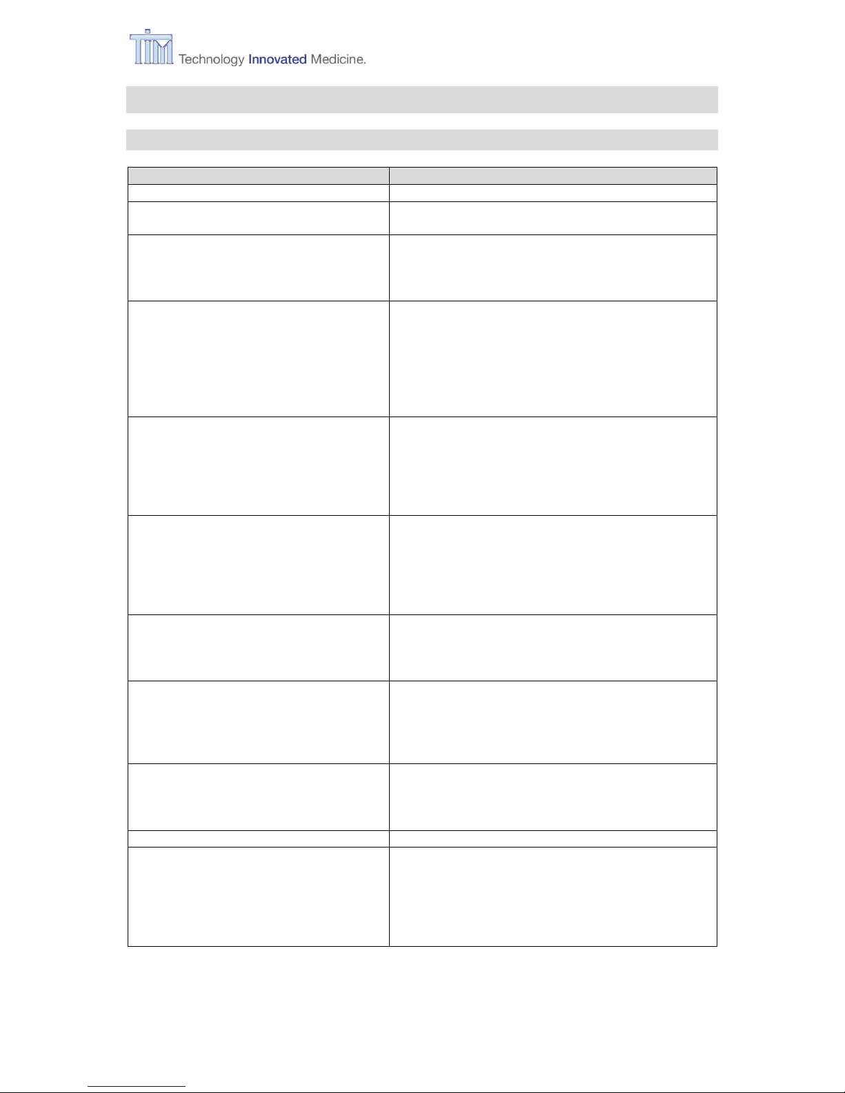
12 High priority alarms
Alarm
What MIRUS Controller does
What to check or to do
Device
inclined!
Device pauses the application and
closes all valves until device is
positioned on a level surface.
1. Reposition device on a level
surface.
Dosage failed!
Start VA?
Device stops the application.
1. Restart VA delivery by
activating Play and Confirm or
turn off device.
Failure!
Turn off.
Device stops the application.
Turn off tag becomes selectable.
A major technical failure was
recognised.
1. Turn off device into OFF mode
(Standby).
2. Wait 5 seconds and try to start
device again.
3. If during self test "Sorry…"
message appears the device is
seriously damaged. Call your
service organisation.
Fill port flap
still open!
Continues working.
1. Close Fill port flap.
Heating
system failed.
Continues working.
1. Turn off device into OFF mode
(Standby).
High et VA
Continues working.
1. Patient okay (CO2, SpO2)?
2. Set MAC okay?
3. Alarm settings okay?
High et CO2
Continues working.
1. Ventilator settings okay?
2. Alarm settings okay?
3. Patient okay?
Interface
disconnected
Device pauses the application.
1. Reconnect MIRUS Interface
plug.
Low et CO2
Continues working.
1. MIRUS Interface okay?
2. Ventilator settings okay?
3. Alarm settings okay?
Low et VA
Continues working.
1. Delivery active (Start button!)?
2. Alarm settings correct?
3. MRUS Interface okay?
Low Vt
Continues working.
1. Patient okay?
2. Ventilator settings okay?
Vt has to be ≥ 200mL!
Occlusion of
Interface
Device pauses the application.
1. MIRUS Interface bent or
pinched?
2. Fresh gas flow of Anaesthesia
Work Station minimum
1.5 * MV?
Reservoir
empty
Continues working.
1. Refill reservoir promptly.
UPS battery
low
Continues working.
1. Allow recharging of battery.
Page 67

Notes
IFU, MIRUS Controller, en-GB, N.00 67
Page 68
12 High priority alarms
Technology Innovated Medicine
www.tim-gmbh.de Technologie Institut Medizin GmbH (TIM) www.tim-products.de
This document
MIRUSTM Controller
Instruction for use
English (GB)
Printed in Germany
© TIM GmbH
All rights reserved
Rev. N.00 of 03/18
Manufactured by
Technologie Institut Medizin
GmbH (TIM)
Erfurter Straße 9
D-56626 Andernach
Germany
T.: +49 (0) 2632 98 76 297
F.: +49 (0) 2632 98 76 299
info@tim-gmbh.de
http://www.tim-gmbh.de
Instructions for use
Service calls
Support & Help
service@tim-products.de
0044
Distributed by
MEDCAPTAIN Europe B.V.
Kerkenbos 1077 T,
6546 BB Nijmegen,
The Netherlands
Phone: +31 (0)24-206 3000
Email:
jurgen.reimer@medcapatain.eu
 Loading...