

Tilton Yard Shark YSH2051Z, Yard Shark YSH2460Z, Yard Shark YSK2560Z, Yard Shark YSK2151Z Operator's Manual
Page 1
Operator’s Manual
Covers Models:
YSH2051Z, YSH2460Z
YSK2151Z, YSK2560Z
Your Authorized Yard Shark Dealer:
Congratulations on the purchase of
your new Yard Shark commercial mower!
Before operating the mower read and understand
this operator’s manual!
Part # YZ2007
Rev 2007-03-26
Page 2

Page 2
Page 3

Page 3
Proudly Distributed by:
Tilton Equipment Company
P.O. Box 68
Rye, New Hampshire 03870-0068
1 About This Manual..........................................................................................................................................6
2 Delivery Checklist............................................................................................................................................7
3 Safety Instructions...........................................................................................................................................8
3.1 Training .....................................................................................................................................................8
3.2 Preparation................................................................................................................................................8
3.3 Maintenance and Storage..........................................................................................................................9
3.4 Serial Number and Model Identification..................................................................................................10
4 Machine Operation........................................................................................................................................11
4.1 Filling The Fuel Tank ..............................................................................................................................11
4.2 Motion Control Levers.............................................................................................................................12
4.3 Parking Brake..........................................................................................................................................12
4.4 PTO Engagement Switch .........................................................................................................................13
4.5 Choke Control..........................................................................................................................................13
4.6 Throttle Control.......................................................................................................................................13
4.7 Ignition Switch.........................................................................................................................................13
4.8 Fuel Gauge / Hour Meter.........................................................................................................................13
4.9 Seat and Armrests....................................................................................................................................14
4.10 Setting Mower Deck Cutting Height........................................................................................................15
4.11 Cold Engine Starting Procedure.............................................................................................................. 16
4.12 Warm Engine Starting Procedure............................................................................................................16
4.13 PTO / Blades............................................................................................................................................16
4.14 Deck Deflector.........................................................................................................................................16
4.15 Stopping PTO...........................................................................................................................................16
4.16 Shutting Down Engine .............................................................................................................................16
5 Service and Maintenance Procedures..........................................................................................................17
5.1 Clean Dust and Dirt From Engine Clean Air Intake Screen & Cooling Fins – Check Daily..................18
5.2 Check Seat Safety Switch Operation – Check Daily ................................................................................18
Page 4

Page 4
5.3
Check Engine Oil Level – Check Daily....................................................................................................18
5.4 Check Mower Blades – Check Daily........................................................................................................18
5.5 Clean Underside of Deck – Check Daily .................................................................................................18
5.6 Air Filter Inspect / Clean.........................................................................................................................19
5.7 Engine Oil / Filter Change.......................................................................................................................19
5.8 Check Hydraulic Oil Level.......................................................................................................................19
5.9 Check Tire Pressure.................................................................................................................................19
5.10 Check / Adjust Deck Drive Belt Tension..................................................................................................20
5.11 Lubricate Control Levers........................................................................................................................21
5.12 Grease Deck Lift Pivots ...........................................................................................................................21
5.13 Grease Front Wheel Axle Bearings..........................................................................................................22
5.14 Check Pump Drive Belt............................................................................................................................22
5.15 Spark Plugs Check/Adjust/Replace..........................................................................................................23
5.16 Air Filter Replace ....................................................................................................................................23
5.17 Check / Adjust Valve Clearances.............................................................................................................23
5.18 Fuel Filter Change...................................................................................................................................23
5.19 Change Hydraulic Filter..........................................................................................................................23
5.20 Change Hydraulic Oil and Filter.............................................................................................................23
6 Service & Adjustments Perform as Needed.................................................................................................24
6.1 Adjusting Throttle Cable..........................................................................................................................24
6.2 Adjusting Choke Cable.............................................................................................................................25
6.3 Deck Adjustments.....................................................................................................................................25
6.4 Transmission Neutral Setting...................................................................................................................26
6.5 Deck Belt Replacement............................................................................................................................28
7 Fuel & Lubricant Recommendations...........................................................................................................28
7.1 Oxygenated Fuels.....................................................................................................................................28
7.2 Fuel Stabilizer / Conditioner....................................................................................................................29
7.3 Engine Oil Recommendation....................................................................................................................29
7.4 Hydraulic Oil Recommendation...............................................................................................................29
7.5 Engine Specifications...............................................................................................................................29
7.6 Hydrostatic System Specs.........................................................................................................................30
7.7 Fuel Tank Capacity............................................................................................................. .....................30
8 Service Record................................................................................................................................................31
Page 5

Page 5
9
Parts lists and drawings.................................................................................................................................33
9.1 Aftermarket Replacement Parts NOT SHOWN in Drawings...................................................................33
9.2 Decals ......................................................................................................................................................34
9.3 Wiring Assemblies....................................................................................................................................36
9.4 Rear Wheel and Wheel Motor Group.......................................................................................................37
9.5 51′′ Deck Group.......................................................................................................................................38
9.6 60′′ Deck Group.......................................................................................................................................40
9.7 Deck Spindle Hub Detail..........................................................................................................................41
9.8 Deck Deflector Detail ..............................................................................................................................42
9.9 Deck Lift Group .......................................................................................................................................43
9.10 Front Caster Group .................................................................................................................................44
9.11 Honda 20hp Engine & Pump Drive Group..............................................................................................45
9.12 Kaw 21,25 & Honda 24 Engine & Pump Drive Group ...........................................................................46
9.13 Seat Group...............................................................................................................................................47
9.14 Fuel Tank Group......................................................................................................................................48
9.15 Hydraulic Pump & Lines Group..............................................................................................................49
9.16 Control Lever Group................................................................................................................................50
9.17 Control Panel Group ...............................................................................................................................51
9.18 Frame Parts Group..................................................................................................................................52
Page 6

Page 6
Congratulations On The Purchase Of Your New Yard Shark Mower.
When you purchase a Yard Shark you are part of a family of satisfied customers – people who
appreciate a mower that will provide you with years of excellent performance, durability, and
trouble free service when operated and maintained as directed in this manual.
Read and understand this operator’s and parts manual and follow all instructions and warnings
before operating this machine.
If you did not sign and receive your copy of your warranty registration, contact your Yard Shark
dealer to do so immediately! Before any warranty service can be authorized you must register this
product with Tilton Equipment Company.
1 About This Manual
This Yard Shark operator’s manual is considered a permanent part of the mower. It must be
available to all operator’s and/or person(s) servicing the mower. Should the mower be resold , this
manual must remain with the mower.
Should you ever have any questions regarding the operation, maintenance, or safety of your
mower, please contact your authorized Yard Shark mower dealer who h as been trained on
operation and service of this mower.
All information, illustrations, and specifications contained in this manual were in effect at the time
of publication. The manufacturer reserves the right to change, modify, and/or discontinue
specifications and/or design without notice. If you notice that a change has been made to your
mower which is not shown or reflected in this manual, please see your authorized Yard Shark
mower dealer before operating or servicing the mower.
This manual identifies potential hazards and has safety messages identified by the safety alert
example symbols shown below, which signal a hazard that may cause serious injury or death if
you do not follow the recommended precautions.
DANGER
WARNING
CAUTION
Failure to follow instructions WILL
result in SERIOUS INJURY or DEATH!
Failure to follow instructions CAN result
in SERIOUS INJURY or DEATH!
Failure to follow instructions can result
in personal injury.
Page 7

Page 7
2 Delivery Checklist
Before you, the owner or primary operator uses this machine, go through this check list so that you
understand the safe and proper operating procedures for your new Yard Shark machine.
________ Read and understand this operator’s manual before ope rating your Yard Shark mower.
________ Understand the “Safety Instructions” section of manual.
________ Record engine and mower serial numbers in space provided.
________ Checking Engine Oil
________ Checking Hydro Oil
________ Filling Fuel Tank
________ Seat and Armrest Adjustments
________ Motion Control Levers and Parking Brake Operation
________ Engine Controls – Throttle/Choke/Ignition Switch
________ Fuel Gauge / Hour Meter
________ Setting Deck Height
________ Cold Engine Start Procedure
________ Warm Engine Start Procedure
________ Deck Deflector
________ PTO / Starting and Stopping Blades
________ Shutting Down Engine
________ Fill Out the Warranty Registration Form through your Yard Shark Dealer.
Page 8

Page 8
3 Safety Instructions
3.1 Training
WARNING
o Read the operator’s manual and other training material. If the operator(s) or mechanic(s)
cannot read English it is the owner’s responsibility to explain this material to them.
o Become familiar with the safe operation of the equipment, operator controls, and
safety signs.
o All operators and mechanics should be trained. The owner is responsible for training
the users.
o NEVER let children or untrained people operate or service the equipment.
Local regulations may restrict the age of the operator.
o The owner/user can prevent and is responsible for accidents or injuries occurring to
themselves, other people or property.
3.2 Preparation
WARNING
o ALWAYS evaluate the terrain to determine what accessories and attachments are needed
to properly and safely perform the job. Only use accessories and attachments approved by
the manufacturer.
o ALWAYS wear appropriate clothing including safety glasses an d hearing protection.
o ALWAYS inspect the area where the equipment is to be used and remove all objects such
as rocks, toys and wire which can be thrown by the machine
o ALWAYS use extra care when handling gasoline and other fuels. They are flam mable and
vapors are explosive.
o ALWAYS use only an approved safety fuel container.
o ALWAYS check that operator’s presence controls, safety switches and shields are
attached and functioning properly.
o ALWAYS be sure all drives are in neutral and parking brake is engaged before starting
engine. Only start engine from the operator’s position.
o ALWAYS slow down and use extra care on hillsides. Be sure to travel in a safe direction
on hillsides. Turf conditions can affect the machine’s stability. Use caution while operating
near drop-offs.
o ALWAYS turn uphill when changing directions while mowing left to right and right to left
on hill sides.
o ALWAYS use care when approaching blind corners, shrubs, trees, or other objects that
may obscure vision.
o ALWAYS stop on level ground, lower implements, disengage drives, engage parking
brake, shut off engine before leaving the operator’s position for any reason including
emptying the catchers or unclogging the chute.
o ALWAYS stop equipment, shut off the engine, set parking brakes and inspect blades after
striking objects or if an abnormal vibration occurs. Make necessary sharpening repairs o r
replace all blades before resuming operations.
o ALWAYS keep hands and feet away from the cutting units.
Failure to follow instructions CAN result
in SERIOUS INJURY or DEATH!
Failure to follow instructions CAN result
in SERIOUS INJURY or DEATH!
Page 9

Page 9
o ALWAYS look behind and down before backing up to be sure of a clear path.
o ALWAYS be aware of the mower discharge direction and do not point it at anyone.
o ALWAYS slow down and use caution when making turn s and crossing roads
and sidewalks.
o ALWAYS stop blades if not mowing.
o ALWAYS use care when loading or unloading the machine into a trailer or tru ck.
o ALWAYS operate in good light, keeping away from holes and hidden hazards.
o NEVER operate with long hair, loose clothing or jewelry that may get tangled in
moving parts.
o NEVER remove gas cap or add fuel when engine is running.
o NEVER smoke while fueling the machine or near any fuels or fuel fumes.
o NEVER refuel or drain the machine indoors.
o NEVER raise deck with the blades running.
o NEVER operate with guards not securely in place.
o NEVER operate with the discharge deflector raised, removed or altered, unless using
a grass catcher.
o NEVER run an engine in an enclosed area.
o NEVER change the engine governor setting or over speed the engine.
o NEVER carry passengers and keep pets and bystanders clear of the work area.
o NEVER operate the mower under the influence of alcohol or drugs.
3.3 Maintenance and Storage
o Disengage drives, lower implement, set parking brakes, stop engine, remove key and
disconnect spark plug wires. Wait for all movement to stop before adjusting, cleaning
or repairing.
o Clean grass and debris from cutting units, drives, mufflers, and engine to help
prevent fires. Clean up oil or fuel spillage.
o Let engine cool before storing and do not store near flame.
o Do not store fuel near flames or drain indoors.
o Park machine on level ground. Never allow untrained personnel to service machine.
o Use jack stands to support components when required.
o Carefully release pressure from components with stored energy
(example, hydraulic components).
o Disconnect battery and remove spark plug wires before making any repairs. Disconnect
the negative terminal first and the positive last. Reconnect positive first and negative last.
o Use care when checking blades. Wrap the blade with a heavy rag or towel or wear gloves,
and use caution when servicing them. If blades are bent or damaged, replace all of the
blades. Never straighten or weld them.
o Keep hands and feet away from moving parts. Do not make adjustments with the
engine running.
o Charge batteries in an open well ventilated area, away from spark and flames.
o Charge battery with a 2 amp charger and disconnect the battery ground cable before
storing the machine for 30 days or more. Improper battery care will void battery warranty.
o Unplug charger before connecting or disconnecting from battery. Wear protective clothing
and use insulated tools.
o Keep all parts in good working condition and all hardware tightened. Replace all worn or
damaged decals.
Page 10
Page 10
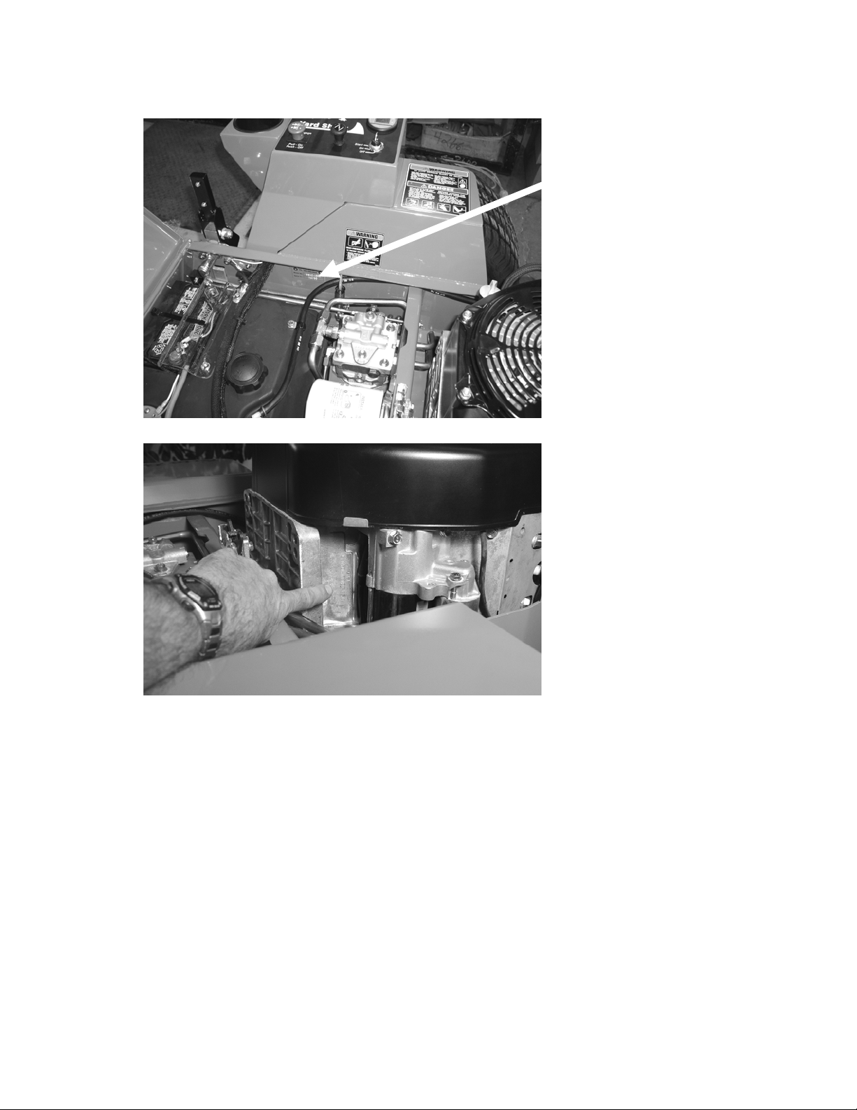
3.4 Serial Number and Model Identification
The serial number/model number tag can be found at the RH side of the mower under the seat in
front of the engine compartment.
The engine serial number can be found on the Front LH side of the engine as shown below.
Record serial numbers here for future reference.
Mower Model Number____________________________
Mower Serial Number____________________________
Engine Serial Number____________________________
Page 11
Page 11
4 Machine Operation
Left Side of machine is determined by sitting in the seat in the operating position.
4.1 Filling The Fuel Tank
WARNING
WARNING
o Fill fuel tank outside in a well ventilated area
o Shut the engine off and set parking brakes.
o Allow engine to cool to ambient temperatures.
Gasoline is extremely flammable and gasoline vapor can
explode. Failure to follow proper procedures can result in
personal injury or death.
Do not add fuel while the engine is running or hot. Keep
open flames, sparks and heat away from fuels and store
fuel in
containers specifically designed for that purpose.
o Unlatch seat and tip forward to access the fuel tank.
o Use a funnel and be careful to not spill fuel.
o Wipe up possible fuel spills and allow to completely dry before re-starting engine
Page 12

Page 12
4.2 Motion Control Levers
Motion Control Levers in Operating Position
Motion control levers are in the operating position when they are as shown above. Left hand lever
controls the speed and direction of the LH drive wheel. Right hand lever controls the speed and
direction of the RH drive wheel.
Moving both levers forward together causes mower to travel forward in a straight line.
Moving both levers rearward together causes the mower to travel in reverse in a straight line.
To turn left while moving forward, pull back slightly on the LH lever. To turn right while moving
forward, pull back slightly on the RH lever.
To make a zero radius turn, move one lever slightly ahead of neutral and the other lever slightly
behind neutral center position.
4.3 Parking Brake
The parking brake system on the Yard Shark mower is not really a brake, but is actually a pin and
cog system that is activated every time the control levers are moved out into the neutral locked
position as shown below. It is an automatic system that sets itself when you move the levers out to
get off the mower and releases itself when you move the levers back in to start moving. If the
mower will not move or sounds like it is straining, simply move the control levers slightly forward or
backwards to release the pin.
Motion Control Levers in Non-Operating Position – Parking Brakes On
Page 13
Page 13
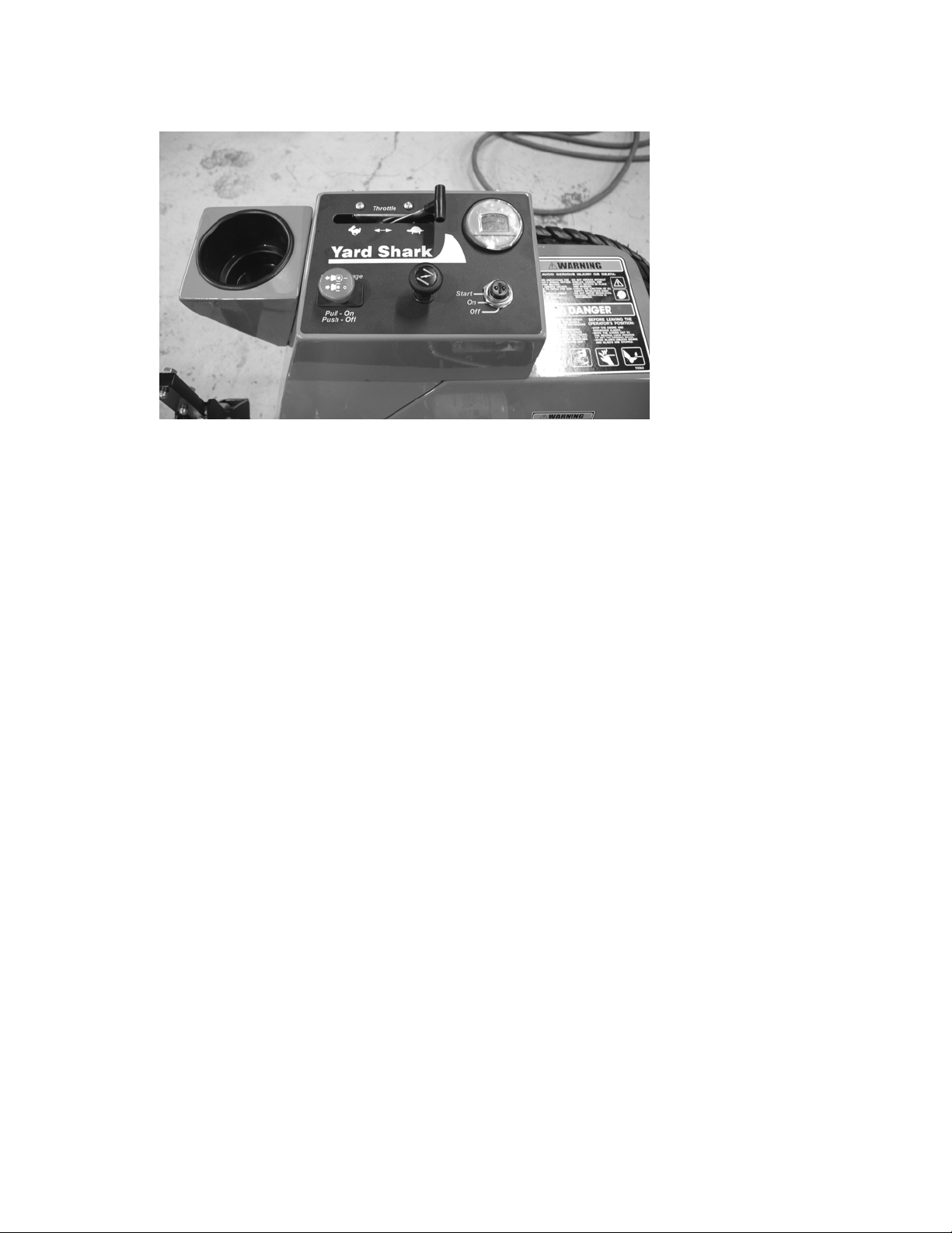
4.4 PTO Engagement Switch
Located on RH control panel. Switch is pulled UP (“ON” position) to engage the blades.
Switch must be in the DOWN or OFF position in order to start the engine.
4.5 Choke Control
Pull choke knob UP or OUT to the choke “ON” position.
Push choke knob DOWN or IN the choke “OFF” position.
4.6 Throttle Control
Move lever forward to increase engine speed.
Move lever to the rear to idle position.
When mowing the throttle should be in the full forward (fastest) position.
4.7 Ignition Switch
Three (3) position switch. The first position is OFF, second position is ON or RUN. The third
position is the start position.
4.8 Fuel Gauge / Hour Meter
Digital display indicates amount of fuel remaining. When red light flashes, unit is very low on fuel
and should be refueled.
Refer to all items in filling the tank (Section 4.1).
The hour meter records time the key is on. Use hour meter to reco rd service intervals.
Page 14
Page 14
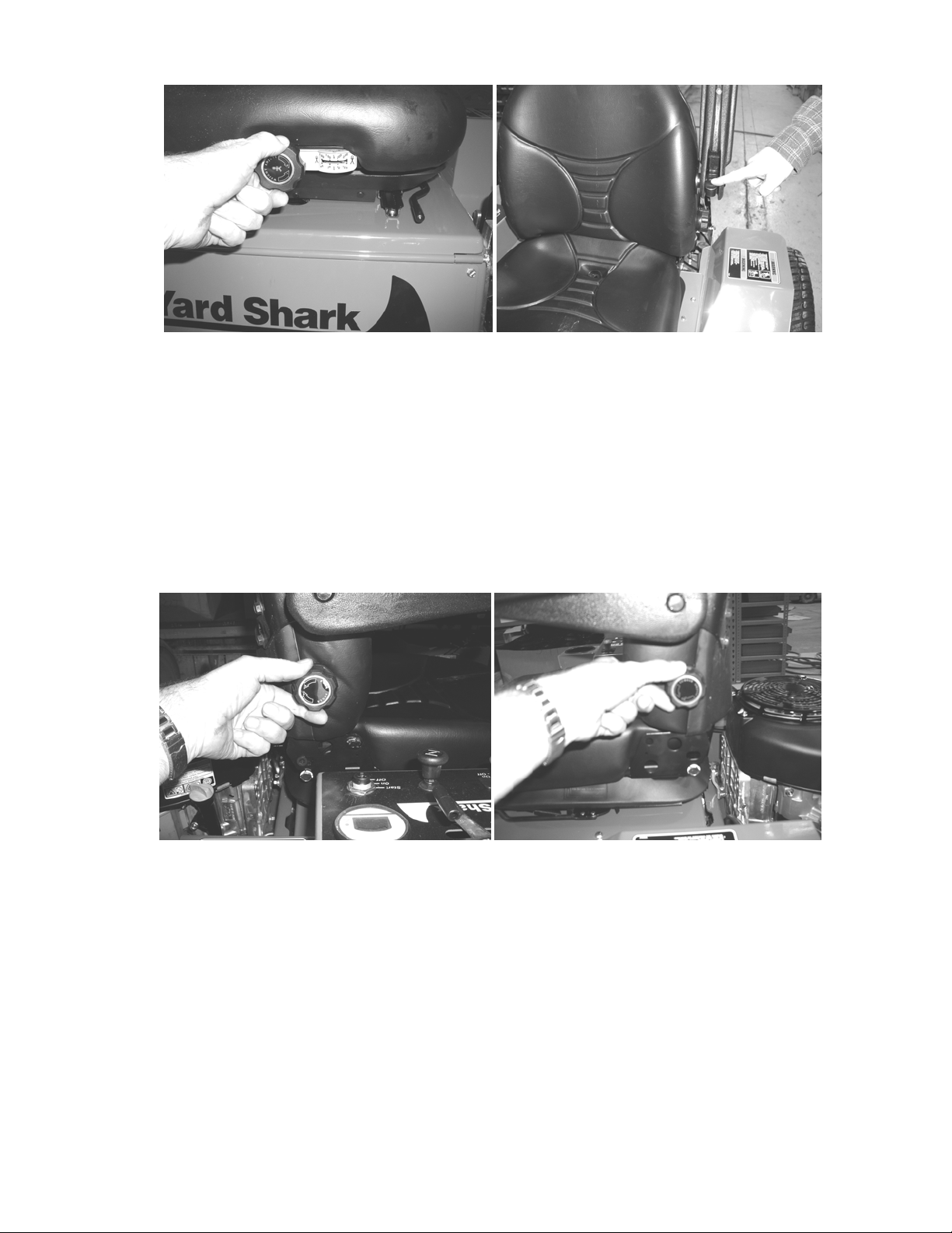
4.9 Seat and Armrests
There are two adjustments at the front of the seat.
The knob controls the stiffness of the suspension seat. This should be adjusted to fit the
operator weight.
The lever, shown above left with an arrow, allows for fore and aft adjustment. While seated, pull
lever to the left to release seat and move seat into desired position. Make sure the latch is fully
locked so that seat is secure.
The armrest height can be adjusted with the small knobs, above right, screw out to raise armrests.
Setting the armrests at the proper height will assist you in maintaining better control of
the machine.
The other settings are located on either side of the seat backrest. The knob on the RH side adj usts
the angle of the backrest. The knob on the LH side adjusts the lumbar support. Adjust these for
your personal preference.
Page 15
Page 15
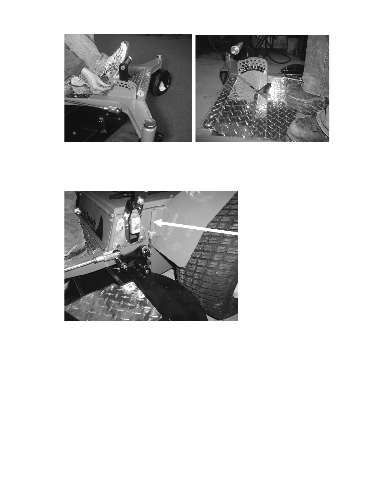
4.10 Setting Mower Deck Cutting Height
While seated on the seat, push on foot lever to raise deck. The deck can now be locked in the
upper position by using the deck latch lever located on the LH side of the mower (shown below).
Move the lever to the rear to engage the deck lock. Remove pin and move to the desired position.
The decal next to the foot lever indicates the cutting height. Moving the pin one hole adjusts the
cutting height by 1/4′′.
To release deck lock, push forward on the deck latch lever while pushing forward with the
foot pedal.
Page 16

Page 16
4.11 Cold Engine Starting Procedure
o Be sure engine has oil to the proper level and gas in the fuel tank.
o Pull up on Choke to “ON”.
o Move throttle control about 1/3 of the way forward.
o Turn key to “START” position and hold until engine starts.
o If engine fails to start within 5 seconds, release the key, wait at least 10 seconds.
o Note: Using the starter for more than 5 seconds at a time can overheat and damage
the starter.
o Gradually push choke knob in as engine warms up.
4.12 Warm Engine Starting Procedure
Same as above but leave choke in the “OFF” position.
4.13 PTO / Blades
DANGER
The PTO switch engages the cutting blades. Be certain everyone including pets are clear of the
mower deck and the RH discharge area before engaging the PTO.
Operator must be seated before the PTO can be engaged. The motor will kill if the seat switch is
not depressed.
Move throttle to halfway position. Pull up on PTO switch to the “ON” position. Then move throttle to
full forward “FAST” position.
4.14 Deck Deflector
DANGER
Deck is equipped with a rubber deck discharge deflector.
Deflector can be pivoted upwards for clearance, for storing or transporting.
NEVER mow with the deflector in the UP position unless using an approved grass
catcher/collector.
Operating PTO creates a thrown object hazard. NEVER
operate with deflector or guards missing. Make sure
discharge chute is not pointed toward pets or bystanders.
Operating PTO creates a thrown object hazard. NEVER
operate with deflector or guards missing. Make sure
discharge chute is not pointed toward pets or bystanders.
4.15 Stopping PTO
In an emergency, deck blades can be stopped anytime by pushing down on the PTO switch, also
by turning the ignition key switch to “OFF”.
Normal operation - move throttle to halfway position. Push down on PTO switch to “OFF” position.
4.16 Shutting Down Engine
In an emergency simply turn the ignition key switch to “OFF”.
For normal shutdown, stop machine, turn off PTO, move throttle all the way to SLOW. Turn ignition
key switch to OFF.
Page 17

Page 17
5 Service and Maintenance Procedures
Service and Maintenance
Procedures
Clean Dust and Dirt From Engine
Clean Air Intake Screen and
Cooling Fins
Check Seat Switch Interlock X
Check Engine Oil Level X
Check Mower Blades X
Clean Underside of Deck X
Air Filter Inspect/Clean X
Engine Oil / Filter Change X X
Check Hydraulic Oil Level X X
Check Tire Pressure X X
Check/Adjust Deck Belt Tension X X
Lubricate Control Levers X
Grease Deck Lift Pivots X
Grease Front Wheel Bearings X
Check Pump Drive Belt X
Spark Plugs Check / Adjust X
Clean Oil Cooler Fins X
Air Filter Replace (Both) X
Spark Plugs / Replace X
Valve Clearance X
Fuel Filter / Change X
Change Hydraulic Filter X X
Change Hydraulic Oil & Filter X
X
Daily
After First
10 Hours
Every 25
Hours
Every 50
Hours
Every100
Hours
Every 300
Hours
Page 18

Page 18
5.1 Clean Dust and Dirt From Engine Clean Air Intake Screen & Cooling Fins – Check Daily
Check for accumulations of dust, grass clippings, dirt, etc. Check around the fresh air intake
screen on top of the engine. Also check cooling fins on engine and oil coolers and clean with
compressed air. Be careful on the Honda 24 so the cooling fins on the separate oil cooler are not
damaged. Remove excess accumulations around the base of the engine, under the se at, around
hydro pumps and the top of the deck. Keeping the machine clean will guarantee a cooler and safer
operating environment.
5.2 Check Seat Safety Switch Operation – Check Daily
WARNING
o When raised off the seat, turn key switch to start.
o Engine should not crank.
o If engine cranks, contact your dealer to resolve this problem before using mower.
o While seated on mower, start engine, then engage PTO.
o With the control levers moved outward to the locked/parking brake position, raise yourself
off the seat.
o Engine should shut off immediately.
o If engine does not shut off, contact your dealer to resolve this problem before
using mower.
5.3 Check Engine Oil Level – Check Daily
At rear right of mower, unscrew dipstick. Wipe clean. Then, reinsert without screwing it in. Add
oil, if needed to bring up to the full mark.
Safety interlock is designed to prevent PTO/blades
operating unless operator is seated. Failure to maintain
proper operation of system can result in injury or death.
5.4 Check Mower Blades – Check Daily
Raise front of mower and check condition of mower blades.
If blades are not sharp they must be sharpened or replaced.
If blades are bent or damaged replace all of the deck blades. Don’t attempt to straighten bent
blades. It is dangerous to straighten because it could cause the blades to crack/break in operation.
5.5 Clean Underside of Deck – Check Daily
While checking conditions of blades, scrape out any accumulated grass clipping from under the
mower deck. Mower performance will deteriorate if blades are not in good condition and grass
builds up under deck.
Page 19

Page 19
5.6 Air Filter Inspect / Clean
Follow instructions in the respective Honda or Kawasaki owner’s manual for details.
5.7 Engine Oil / Filter Change
o Drain used oil while the engine is warm. Warm oil drains quickly and more completely.
Replace oil filter at each oil change.
o Place a suitable container under the engine to catch used oil.
o Remove the oil filler cap / dipstick, drain plug and oil filter. Allow used oil to
drain completely.
o Reinstall drain bolt and tighten securely.
o Clean the filter mounting base and coat the rubber seal on the new filter with new
engine oil.
o Screw on the new filter by hand until seal contacts filter base, then tighten another
3/4 - 7/8 turn, alternatively tighten to 16 lbf-ft (22Nm).
o Refill crankcase with new oil (See engine operator’s manual for proper oil selection).
o Start engine and check for leaks. Stop engine then check oil level. Add oil if needed to
bring oil to top of safe mark.
o Dispose of used oil and filter at local recycling center and obey all local and federal laws
for these products.
5.8 Check Hydraulic Oil Level
o Be extremely careful with dirt and contamination when you are servicing the
hydrostatic system.
o Contamination is the worst enemy of the hydrostatic system.
o Clean around dipstick and filters BEFORE removing.
o Only add oil from a sealed container.
o Thoroughly clean funnels and anything that will come into contact with the oil.
o Contamination in the system will void the warranty on the hydrostatic system.
o Check level when oil is cold.
o Unscrew dipstick and wipe clean. Insert into oil tank without screwing it in. If oil shows
on the dipstick (approximately 1/4″-1/2″ up from the bottom), then the oil level is adequate.
If no oil shows on dipstick, then add oil to bring up to the dipstick. The upper mark is a high
level mark for when the oil is hot. If oil tank is overfilled, oil will expand and come out of the
dipstick / vent when the oil gets hot.
o See Section 7.4 for proper oil recommendation.
5.9 Check Tire Pressure
Inflate all 4 tires to 12 psi. A special low pressure air gauge (available at most auto parts stores)
should be used to accurately check the pressure.
Page 20

Page 20
5.10 Check / Adjust Deck Drive Belt Tension
o Spring for deck belt tension can be found by looking under the RH side of the mower.
To check belt tension, measure the length of the spring. The body of the spring should
measure 3-1/2′′ to 3-3/4′′.
o An alternative method is to use a U.S quarter, to use as a feeler gauge between the coils.
Spring tension is correct when quarter will just fit between coils with minimal resistance.
If belt tension needs adjusting remove hair pin and unhook the deck belt tension arm from its stud
at the front of the deck (photo above).There are 2 holes for the arm to hook into. Use the front hole
for normal operation. If belt becomes stretched enough that you can’t get the proper tension then
use the second hole.
Page 21

Page 21
Go to left side of mower. Loosen the flat idler pulley (use a 9/16′′ wrench) and move slightly to the
rear. Retighten pulley, rehook spring tension arm and recheck spring length. Adjust until body of
spring measures 3-1/2′′ to 3-3/4′′ or a quarter fits snugly between the coils.
5.11 Lubricate Control Levers
o Raise seat. Use a grease gun with multipurpose grease.
o Grease zerks at the control arm pivots (2).
o Use a light “dry lube” type spray lubricant (use a dry lube containing Teflon or “moly” )to
lube the brake linkage and the control arms.
o Lubricate the pivot for the park lock position, where the side plates of the handle mount to
the control arm block.
o Applying a small amount of multipurpose grease to the tab that actuates the parking lock
will make the entire park lock system work more smoothly.
o Use (2) 3/4′′ wrenches to adjust the amount of tension on control lever arm mounts so the
levers have the proper amount of resistance. (This is a personal preference on how stiff to
make the arms to move back and forth from the locked position to the travel position).
5.12 Grease Deck Lift Pivots
Use a grease gun with multipurpose grease. Grease zerks at the rear deck lift pivots (2).
Page 22

Page 22
5.13 Grease Front Wheel Axle Bearings
Use a grease gun with multipurpose grease. Grease the zerks on e ach the front wheels. One zerk
per wheel.
5.14 Check Pump Drive Belt
Raise rear of mower to access pump drive belt. Use blocks as necessary to support mower safely.
Pump belt idler arm should be free to move with firm hand force. If arm is sticky or stiff, remove
arm and coat the mounting surfaces with anti-seize lubricate. Reassemble and adjust tension at
pivot bolt. Proper tension can be achieved by tightening ½′′ nut on pivot bolt until spring washers
are compressed, then back off ¼ turn. Arm should be free to move with firm hand force. Install the
lock nut and tighten making sure that the adjustment is not changed.
Measure length of the spring – Proper length is 4-1/4′′ inside spring hooks, OR length of coils
should measure 3-1/4′′.
Another method to check tension – A quarter ($.25 US coin) should just fit in between the coils in
the spring.
Adjust position of idler to achieve proper belt tension. Use (2) 9/16′′ wrenches to move the idler in
its adjustment slot.
Page 23

Page 23
5.15 Spark Plugs Check/Adjust/Replace
Disconnect spark plug caps.
Remove dirt from around spark plug areas.
Remove the spark plugs with a 13/16 spark plug wrench.
Replace plugs if the electrodes are worn or if insulator is cracked or chi pped.
Regap spark plugs to .030′′ (.75 mm).
Reinstall plugs by hand, be careful to avoid cross threading.
To reinstall used plugs, tighten 1/8-1/4 turn after the spark plug seats lightly.
To install new spark plugs, remove old plugs and gap new plugs.
Thread new spark plugs into engine by hand, then use a 13/16′′ spark plug wrench and tighten
1/2 turn after the spark plug seats. (or tighten to 16 ft lb.)
5.16 Air Filter Replace
Each year or 300 hours replace primary (paper) air filter elements. Follow instructions in resp ective
engine owner’s manual. Secondary filter should be replaced according to engin e owner’s manual.
5.17 Check / Adjust Valve Clearances
Both Kawasaki and Honda recommend valve clearance be checked every year or 300 hours.
This should be performed by your servicing dealer unless you have the proper t ools and are
mechanically adept. Refer to Honda or Kawasaki shop manual for procedure s.
5.18 Fuel Filter Change
Replace every year or 300 hrs, replace sooner if it becomes clogged.
Consult engine owner’s manual for instructions.
5.19 Change Hydraulic Filter
o Place a pan under the hydrostatic oil filter, unscrew oil filter enough so the oil can drain
into the oil pan. It is possible to get a little oil on the drive belt at this point. It is
recommended to place a small shield over the belt to prevent it from coming into contact
with the oil.
o Allow oil to drain completely
o Apply a thin film of clean oil to oil filter seal.
o Screw filter on by hand until seal contacts base, then tighten an additional 3/4 turn.
o Add proper oil to bring up to proper level – See section 5.8 in this manual.
o See Section 7.4 for proper oil recommendation.
o Dispose of used oil and filter at local recycling center and obey all local and federal laws
for these products.
5.20 Change Hydraulic Oil and Filter
o Be extremely careful with dirt and contamination when you are servicing the
hydrostatic system.
o Contamination is the worst enemy of the hydrostatic system.
o Clean around dipstick and filter BEFORE removing.
o Only add oil from a sealed container.
o Thoroughly clean funnels and anything that will come into contact with the oil.
o Contamination in the system will void the warranty on the hydrostatic system.
o Place a pan under the oil tank, remove magnetic oil plug and drain the oil.
Page 24

Page 24
o Place a pan under the hydrostatic oil filter, unscrew oil filter enough so the oil can drain
into the oil pan. It is possible to get a little oil on the drive belt at this point. It is
recommended to place a small shield over the belt to prevent it from coming into contact
with the oil.
o Allow oil to drain completely
o Thoroughly clean the drain plug and replace.
o Apply a thin film of clean oil to oil filter seal.
o Screw filter on by hand until seal contacts base, then tighten an additional 3/4 turn.
o Add oil to hydraulic reservoir until oil shows on the dipstick, approximately 7 quarts.
o See Section 7.4 for proper oil recommendation.
o To prime system – raise the rear of mower so that the rear wheels can spin freely.
o Secure machine with jack stands.
o Start engine and run at idle.
o Immediately push both levers full forward and hold for 10 seconds. Then pull both levers
fully rearward and hold for ten seconds. Repeat this procedures several times until all air is
purged from the system.
o Lower mower to the ground and check oil level. The oil level should be approximately 1/2′′
on the dipstick without the cap screwed in. Add oil to bring to proper level.
o Screw dipstick / cap onto hydraulic reservoir.
o Dispose of used oil and filter at local recycling center and obey all local and federal laws
for these products.
6 Service & Adjustments Perform as Needed
6.1 Adjusting Throttle Cable
o If the throttle cable is not properly adjusted, the engine may not be operating at full speed
or the throttle may not stay in the fast position.
o Procedure should be done on a cold engine to prevent any chance of burns from the
hot engine.
o Shut down mower, set parking brakes and remove the key.
o Move throttle lever full forward until it reaches its limiting stop and then back off about
1/8′′ - 1/4′′.
o Go to rear of mower. Throttle linkage should be fully opened (fast position).
o Loosen the clamp on the throttle cable and pull cable tight so the throttle is fully open.
o Retighten clamp.
o If throttle doesn’t hold its position while mowing, then the friction discs on the throttle lever
need to be tightened.
o Remove the cover on the control panel. Use a 7/16′′ combination wrench and a 7/16′′
socket to adjust the tension on the throttle pivot.
o Adjust pinch bolt so that it is tight enough to hold throttle in position.
Page 25

Page 25
6.2 Adjusting Choke Cable
If choke cable is not properly adjusted, it is possible that either the choke won’t fully close or fully
open. This will cause either hard starting, rough running or poo r fuel economy.
When the choke control is pushed all the way in (off), the knob should not contact the base of the
choke mounting. There should be about a 1/8′′ - 1/4′′ gap as shown below.
If adjustment is needed, go to back of mower. Loosen the clamp holding the choke cable.
Now position choke knob 1/4′′ up. Go to rear of mower and gently push choke cable to the right
(opens choke) and tighten screw on cable when the choke is fully opened.
6.3 Deck Adjustments
To level the cutting deck, proceed as follows. Set mower deck at 3″ cutting height.
Measure from top of frame rail to top of deck as shown below.
Page 26

Page 26
The front left and front right measurements should be within 1/16′′ of each other. If adjustment is
needed at the front, adjust the front rockshaft hangers (as shown below).
The hangers at the front rockshaft (shown above) provide vertical adjustment. Normally these
hangers are adjusted all the way UP. If one side of the deck is higher that the other, loosen the
bolts at the higher side of the deck and move hanger slightly lower so that equal measurement is
achieved at both sides. When equal measurements are achieved, proceed with the rear
adjustment.
Measure from the top rear of the frame rail to the deck top on both sides of the machine (as
shown above). These measurements should be within 1/16” of each other and should also be
1-3/4″ – 1-7/8″ less than the measurement at the front of the deck to the top of the rail. This will
make the rear of the blades cut slightly higher than the front of the blades.
If adjustment is needed, remove cotter pin and clevis pin at the front of the lift linkage rods.
Shorten or lengthen linkage rod to achieve the proper height.
When adjustment is complete, all 4 carrier links should have equal pressure on them.
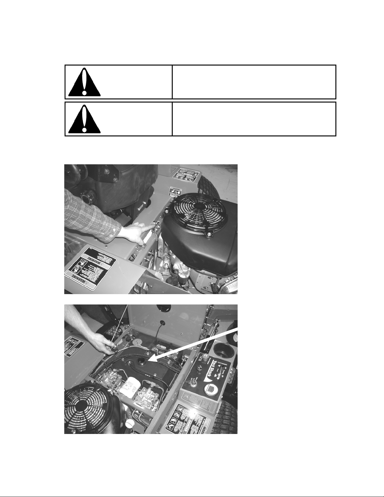
6.4 Transmission Neutral Setting
If mower creeps when levers are in the neutral position (not the locked position) then the neutral
position needs to be adjusted. Do the adjustments in this order only.
o Raise rear of mower slightly off the ground so the rear wheels can turn freely.
o Secure machine with jack stands.
o Control levers should be in the operating position (handles together).
o With engine at a fast idle, wheels should not be turning.
Page 27

Page 27
o Proceed with adjustment as follows.
o Adjust centering on pumps first. To adjust pump neutral – use a 17mm open end wrench
and an 8mm open end wrench.
o Use the 17mm wrench to loosen the locknut (loosen just enough to turn eccentric with the
8mm wrench). Turn eccentric back and forth to see which way it needs to be adjusted.
Adjust so wheel stops turning. When wheel stops turning move the lever forward and
backward and let return to neutral. If necessary, readjust until neutral is achieved then
retighten locknut with the 17mm wrench.
Picture above shows location of adjustments.
o Shut down engine and lower mower to the ground.
o When the pumps’ neutral positions have been readjusted, the linkage rods will have to be
adjusted, also.
o With engine off, and control handles in the operating position, check linkage adjustment.
As you move the levers into the parking lock position the tab at the lower end of the control
levers should enter the square hole perfectly centered. Neither side of the tab should
touch the sides as the lever is moved into its locked position. The locations are shown in
the figures below.
Page 28

Page 28
Loosen 5/16′′ locknuts on the linkage rod. Keep in mind that the nuts at the rear of the rods are left
hand thread and the nuts at the front are right hand thread. Turn linkage rod to lengthen or shorten
as needed so correct alignment is achieved.
Retighten locknuts, then recheck alignment. Readjust or fine tune as nece ssary.
6.5 Deck Belt Replacement
Lower deck to its lowest position.
At front of mower deck, remove hairpin clip and lift spring tensioning arm off of its stud.
Flip up the deck pulley covers with the step plates on them on the LH and RH sides of the deck.
Covers can be locked in an open position by opening up 90 degrees and inserting a pin, bolt or
screwdriver in the hole.
Belt can now be removed.
Replace worn belt with the new belt.
Reattach the spring tensioning arm onto its stud, replace hairpin clip.
Follow directions in previous section to adjust to proper tension.
Recheck tension after first few hours as it is normal to have to adjust the belt tension until the belt
becomes “broken in”; see belt tensioning in Section 5.10.
7 Fuel & Lubricant Recommendations
WARNING
Use unleaded gasoline with a pump octane rating of 89 or higher.
These engines are designed to run on unleaded gasoline. Unleade d gas produces fewer engine
and spark plug deposits and extends exhaust system life.
Never use old or stale gasoline or an oil/gas mixture. Avoid getting dirt or water in the tank.
Gasoline is extremely flammable and gasoline vapor
can explode. Failure to follow proper procedures can
result in personal injury or death.
7.1 Oxygenated Fuels
To meet clean air standards, some area of the United States and Canada use oxygenated fuels to
reduce emissions. If you use an oxygenated fuel, be sure it is unleaded and meets the minimum
octane rating of 89.
Ethanol – (ethyl or grain alcohol) 10% by volume. You may use gasoline containing up to 10%
ethanol by volume. Ethanol blends may be marketed under the name “Gasohol”.
Page 29

Page 29
If you notice any undesirable operating symptoms, try another source of gasoline.
Fuel system damage or performance problems resulting from the use of an oxygenated fuel
containing more than the percentages of oxygenates listed above are not covered under warranty.
7.2 Fuel Stabilizer / Conditioner
Use a fuel stabilizer / conditioner to keep gasoline fresh if mower is to be stored longer than 30
days. Fuel stabilizers are most effective when mixed with fresh fuel. Fuel stabilizers will NOT make
old gasoline fresh.
7.3 Engine Oil Recommendation
See engine owner’s manual for proper oil recommendations for the engine on your mo wer.
7.4 Hydraulic Oil Recommendation
We recommend the use of a Universal Tractor Hydraulic Oil.
Viscosity – 60 SUS (10cSt) at no more than 212deg F (100 deg C)
Some acceptable choices are as follows:
o John Deere: J20A, JD20C, Hy-Gard
o Case-IH: Hy-Tran, Hy-Tran Plus, Hy-Tran Ultra
o AGCO: Power Fluid 821, 821XL
o Cenex: Qwiklift HTB, Maxtron THF+
7.5 Engine Specifications
7.5.1 Model YSH2051Z – Honda 20 hp w/ 51′′ Deck
o Make / Model Honda GXV-620
o Engine Type 4-stroke, Overhead Valve, 2 cylinder, 90° V-Twin
o Displacement 37.5 in³ (614 cm³)
o Bore x Stroke 3.03′′ x 2.60′′ (77mm x 66mm)
o Maximum Output 20 bhp (14.9kW) at 3600 rpm
o Maximum Torque 32.5 lbf-ft (44.13 N-m) at 2500 rpm
o Cooling System Forced Air
o Ignition System Transistorized Magneto
o Spark Plug Gap 0.028′′ – 0.031′′ (0.70 mm – 0.80 mm)
o Spark Plug Denso - J16CR-U
o Engine Oil Cap. 2.3 US quarts w/ oil filter change, 1.8 qts. w/o filter change
o Engine Speeds Idle 1,400 ±150 rpm; Fast 3,600 rpm.
7.5.2 Model YSH2460Z – Honda 24 hp w/ 60′′ Deck
o Make / Model Honda GXV-670
o Engine Type 4-stroke, Overhead Valve, 2 cylinder, 90° V-Twin
o Displacement 40.9 in³ (670 cm³)
o Bore x Stroke 3.03′′ x 2.83′′ (77mm x 72mm)
o Maximum Output 24 bhp (17.9kW) at 3600 rpm
o Maximum Torque 37.5 lbf-ft (50.8 N-m) at 2500 rpm
o Cooling System Forced Air
o Ignition System Transistorized Magneto
o Spark Plug Gap 0.028′′ – 0.031′′ (0.70 mm – 0.80 mm)
o Spark Plug Denso - J16CR-U
o Engine Oil Cap. 2.6 US quarts with oil filter change, 2.1 qts w/o filter change
o Engine Speeds Idle 1,400 ±150 rpm; Fast 3,600 rpm.
Page 30

Page 30
7.5.3 Model YSK2151Z – Kawasaki 21 hp w/ 51′′ Deck
o Make / Model Kawasaki FH641V
o Engine Type 4-stroke, Overhead Valve, 2 cylinder, 90° V-Twin
o Displacement 41.19 in³ (675 cm³)
o Bore x Stroke 2.96′′ x 2.99′′ (75.2mm x 76mm)
o Maximum Output 21 bhp (15.7 kW) at 3600 rpm
o Maximum Torque 38.4 lbf-ft (52.1 N-m) at 2400 rpm
o Cooling System Forced Air
o Ignition System Solid State Ignition
o Spark Plug Gap 0.030′′ (0.75 mm)
o Spark Plug Denso W16EPR-U
o Engine Oil Cap. 1.8 US quarts with oil filter change, 1.6 qts w/o filter change
o Engine Speeds Idle 1,550 rpm; Fast 3,600 rpm.
7.5.4 Model YSK2560Z – Kawasaki 25 hp w/ 60′′ Deck
o Make / Model Kawasaki FH721V
o Engine Type 4-stroke, Overhead Valve, 2 cylinder, 90° V-Twin
o Displacement 41.19 in³ (675 cm³)
o Bore x Stroke 2.96′′ x 2.99′′ (75.2mm x 76mm)
o Maximum Output 25 bhp (18.6 kW) at 3600 rpm
o Maximum Torque 41.3 lbf-ft (56.0 N-m) at 2400 rpm
o Cooling System Forced Air
o Ignition System Solid State Ignition
o Spark Plug Gap 0.030′′ (0.75 mm)
o Spark Plug Denso W14EPR-U
o Engine Oil Cap. 1.9 US quarts with oil filter change, 1.6 qts w/o filter change
o Engine Speeds Idle 1,550 rpm; Fast 3,600 rpm.
7.6 Hydrostatic System Specs
Hydrostatic Pumps (2) White KP Series;
Displacement – 10cc / revolution; Variable displacement, axial piston pump.
Wheel Motors (2) White RG Series; 12.2 in³ (200cc)
Component Manufacturer White Hydraulics, Inc.,
PO Box 1127
Hopkinsville, KY. USA 42241
System Capacity 2.1 US gallons (8.0 litres)
7.7 Fuel Tank Capacity
7.0 US gallons (26.5 litres)
Page 31

Page 31
8 Service Record
Record all service and repairs here for future reference.
Performed
By
Date
Hours
Description of Service Performed
Page 32

Page 32
Page 33

Page 33
9 Parts lists and drawings.
9.1 Aftermarket Replacement Parts NOT SHOWN in Drawings
Spare Ignition Key Y3887
Pin Spanner Tool for Spindle Repair Y4259
Orange Touchup Paint
(1 can Rim Orange)
Air Filter – Primary
(Outer)
Air Filter – Secondary
(Inner)
Fuel Filter
Oil Filter
Spark Plug
YET-4381
Honda 20 hp Honda 24 hp Kawasaki 21 Kawasaki 25
Tilton Part No. Y4849 Y3974 Y3375 Y3375
OEM Part No. 17210-Z J 1-842 17210-7 59-013 11013-7020 11013-7020
Tilton Part No. N/A N/A Y3376 Y3376
OEM Part No. N/A N/A 11013-7019 11013-7019
Tilton Part No. Y4195 Y4195 Y3378 Y3378
OEM Part No. 16910-ZE8-015 16910-ZE8-015 49019-7001 49019-7001
Tilton Part No. Y4168 Y4168 Y3374 Y3374
OEM Part No. 15400-PLM-A01PE 15400-PLM-A01PE 49065-2078 49065-2078
Tilton Part
No.(Denso)
Denso
J16CR-U
Denso
J16CR-U
Denso
W16EPR-U
Denso
W14EPR-U
Page 34

Page 34
Decal Y3351 – Qty (1) – Placement as shown above.
Decal Y3356 – Qty(1) - Place underneath
seat plate next to battery compartment.
Decal Y3361 – Qty (2) – Place
under deck pulley covers on LH
and RH sides of deck.
Decal Y3365 – Qty(2) – Place one
on each side of rear “YardShark”
guard, close to the rear in vicinity of
muffler.
Decal Y3366 – Qty(1) – Place on inside
of LH fender, next to seat.
Page 35

Page 35
Decal Y3362 – Qty(1) – Place on top of LH
fender.
Decal Y3359 – Qty(1) - Place on
RH side of deck near discharge
chute.
Decal Y3363 – Qty(1) – Place on top of RH
fender.
Decal Y3352 – Qty(1) – Place by
adjustment holes by deck lift pedal.
Decal Y3360 – Qty(1) - Place
on LH side of deck.
Page 36

Page 36
Y3746 – Qty(1) - Seat switch wire
harness
Y3748 – Qty(1) – Main engine/clutch
wire harness
Y3747 – Qty(1) – Wire assy, main power
Y3750 – Qty(1) – Fuel gauge plug assy.
Y3751 – Qty(1) – Deck switch wiring assy.
Y4481 – 8” Battery Cable
Qty(1) for Hondas
Qty(2) for Kawasakis
Y4482 – Qty(1) - 40” Battery Cable
Y3749 – Qty(1) – Wire assy, key switch
Y3752 – Qty(1) – Relay wiring assy
Y7611 – Qty(1)
– 30 amp bladetype fuse
Y3784 –
Qty(2) Relay
Electrical & Wiring Group
Y3753 – Qty(1) –
Ground wire
Page 37

Itm Qty Part No. Description
Page 37
1
2 Y1006 1/4−20 Top Lock Nut
2 8 Y1007 NUT, 1/2" UNC TOP LOCK
3 4
4
5
6 2 Y196314 1/8 x 2 Cotter Pin
7
8 2 Y30111 5 Bolt Wheel Hub
9 4 Y3458
10
2
Y1594
2 Y191246 1/4 x 1−1/4 UNC Bolt
10 Y193093 1/2−20 UNF Lug Nut
2 Y2692 White CE−14 Wheel Motor
8 Y3972 Hex Cap 1−2x2_3−4 UNC GR5 ZN
9
9
3/16 x 1 Roll Pin
1/2" SAE Flat Washer
7
14
7
4
Itm Qty Part No. Description
11
2 Y4250 3/32 x 1/2 Cotter Pin
12 1 Y4251 Brake Pin Rocker − RH
13 1 Y4258 Brake Pin Rocker − LH
14
2 Y4308 Compression Spring, Brake Pin
15 2 Y4426
16 2 Y4626 Brake Disc
17
2 Y4627 Brake Rod Support at Wheel Motor
10
18
19 2 Y4637 Brake Pin
20
2
Y4630
10
Y4680 Hex Cap 1−2x2_3−4 UNF
10
1/4" SAE FLAT WASHER
Brake Disc Spacer
6
20
16
8
3
12
15
11
4
1
3
11
13
19
17
18
5
Rear Wheel for 60" Mowers − (2) Y3991 − 23x9.50−12−Zero Offset
Rear Wheel for 51" Mowers − (2) Y3989 − 23x9.50−12−1.25" Inset
Rear Axle and Wheel Motor Group
Page 38

Itm Qty Part No. Description
Page 38
1 3
9 3 Y190063
11 1
13 4
15 4 Y2928 Rubber Bumper
16 2
17 4
19 3 Y30207 DECK ROLLER, 3" x 5"
20 6 Y3458
Y1002 1/2−13 Hex Nut
HAIR PIN, #3 FOR 3/8" PINS
Y191332 Hex Cap 3−8x1_1−4 UNC
Y196304 1/8 X 3/4 COTTER PIN
Y2988
Y30064 Torsion Spring − Mower
5/32 x 3/4 Cotter Pin
1/2" SAE Flat Washer
22
17
Itm Qty Part No. Description
41
3
21
22 1 Y3765
24 2 Y4002 Hex Cap 1−2x3_1−2 UNC
28
29 1 Y4313 RH Pulley Cover
30 2 Y4314 Pulley Cover Hinge
31 1 Y4333 Belt Tensioner
32 1 Y4334 Pulley Cover Tread Plate LH
33 1 Y4335 Pulley Cover Tread Plate RH
Y3637
1 Y4311
33
Deck Roller Pin
V−Belt 51" YardShark
LH Pulley Cover
29
42
15
28
Itm Qty Part No. Description
34
16 Y4349 3/8 SAE FLAT WASHER
35 2 Y4350
1 Y4372
38
41
8 Y4376 3/16 X .250 Std Pop Rivet
42 4 Y4377
44 1 Y4660 51 Deck Weldment − Tilton
1 Y4745
46
47 2 Y6916 DECK WHEEL
48 1
32
Y7790 1/4 X 3/4 Tapping Screw
3/8 X .056 BELLEVILLE WASHER
3/8 Std NC Nylock Nut
NUT, 8−32 UNC KEPS
Rubber Discharge Deflector Assy
35
34
35
13
30
38
46
16
31
9
16
1
11
24
20
47
20
48
21
FRONT VIEW
19
20
44
YardShark 51" Deck Group
Page 39

Itm Qty Part No. Description
Page 39
1 3
2 2 Y1006 1/4−20 Top Lock Nut
3 12 Y1018 Hex Cap 3−8x1 UNC
4 1 Y1045
5
6 1 Y1658 Hex Cap 3−8x2 UNC
7
8 14 Y1827 3/8" Lock Washer
9 3 Y190063
10
11 3
Y1002 1/2−13 Hex Nut
1/2−13 UNC Jam Nut
3 Y1053 1/2" Lock Washer
2 Y1826 3/8−16 UNC Hex Nut
HAIR PIN, #3 FOR 3/8" PINS
2 Y191242 Hex Cap 1−4x_3−4 UNC
Y191422
12
1/2 x 1−1/2 UNF Hex Cap Screw
22
19
4
1
8
20
Itm Qty Part No. Description
12 2 Y198119 1/2 X .070 BELLEVILLE WASHER
13 1 Y30065
14 3 Y30207 DECK ROLLER, 3" x 5"
15
6 Y3458 1/2" SAE Flat Washer
16 3 Y3637 Deck Roller Pin
17 3 Y3862
3 Y4145
18
19 3 Y4203 Deck Idler Pulley Assy − Flat
20 2 Y4225 3/8 x 2.25 Carr Bolt
1 Y4333 Belt Tensioner
21
22 16 Y4349
9
21
7
Deck Belt Tightening Spring
Spindle Assy Mowers 2006−
18" Blade − Std.
3/8 SAE FLAT WASHER
13
19
7
8
22
25.2
6
22
19
26
Itm Qty Part No. Description
1
23
24 1 Y4371 1/2−13 X 1−3/4 Carr Bolt
25 3 Y4374 BK57 X 1" Pulley Assy w/ 2 set
25.1 1 Y7187 BK57−1" Pulley
25.2 1 Y4123
25.3 1 Y192575
26
27
28 1 Y4660 51 Deck Weldment − Tilton
29
25.1
25.3
Y4358 Belt Tensioner Arm
screws
SetScrew 5_16−18 UNCx0.25
Knurled
SetScrew 5_16−18 UNCx0.375 −
Knurled
3 Y4375 1/4 x 1 Key
3
Y4466
2 Y4674 Rear Deck Lift Pin
3
8
BLADE SPINDLE WASHER
22
28
12
20
23
17
27
18
5
11
REAR VIEW
29
9
24
15
10
16
14
2
YardShark 51" Deck Group
Page 40

Itm Qty Part No. Description
Page 40
1 3
2
2.1 1 Y3946 BK62−1" BORE PULLEY
2.2 1 Y4123
2.3
3 1 Y3973
4 1 Y4640 60" Deck Weldment
Y2978 20−1/2" Blade − Std.
3
Y3947 BK62 Pulley Assy w/ 2 Set Screws
SetScrew 5_16−18 UNCx0.25 Knurled
1
Y192575 5/16−18 SET SCREW X 3/8
Belt for 60" YardShark
3
4
2.1
1
Parts unique to 60" deck.
All other parts same as
51" deck.
Yard Shark 60" Deck Group
Page 41

Complete Spindle Assy − # Y3862.
Page 41
Itm
Qty Part No.
1 1 Y1074
2 2 Y2755
3 1
5
1
2
6
3
4 1 Y3863
5 1
6
2
Y2959M Machined Hub for Mower Spindle
Y3864 Spindle Nut for Bottom of #3862 Assy
3
Y3865 Ext Ret Ring MSR−30
4
Internal Retaining Ring/MHO−62/ANSI Metric
6206 SEALED BEARING
Spindle Shaft for #3862 Assy
Description
Blade Side
Pulley Side
6
SECTION A-A
SCALE 3 / 4
AA
6
2
1
5
6
3
4
6
6
2
Spindle Assembly
Page 42

Itm
Page 42
Qty Part No.
1 2 Y198046 1/4" Fender Washer
2 2 Y3624
3
6 Y4060 1/4 x 1 Carr Bolt
4 8 Y4062
5 1 Y4730
1
6
7 1 Y4734 Rubber Deflector−Tilton
6
4
Y4732
1/4 x 1 Hex Cap Screw
1/4 Std NC Nylock Nut
Deflector Bottom Clamp Strap
Deflector Mount Weldment
4
Description
7
1
2
3
5
Rubber Discharge Deflector Assy
Page 43

Itm Qty Part No. Description
Page 43
1 1
2
3 1 Y1053 1/2" Lock Washer
4 2
5
6 4 Y3458
7 4 Y4153 1/2−13 UNC Clevis RH
8
9 2 Y4170
15
Y1019
4 Y1045
Y2952
8 Y2988 5/32 x 3/4 Cotter Pin
10
Y4159 O−Ring
Hex Cap 1−2x1_1−4 UNC
1/2−13 UNC Jam Nut
5/32 X Cotter Pin
1/2" SAE Flat Washer
CLEVIS PIN, 5/8 x 1 1/4
17
16
Itm Qty Part No. Description
10 1 Y4274
11
2 Y4276 DECK PUSH ARM
12 4 Y4348
13 1
14 1
15 4 Y4362 DECK LIFT LINK
16 2 Y4453 DECK LIFT ROD
17 1
15
Y4359
Y4360 FOOT PEG
Y4672 REAR LH DECK LIFT w/ LATCH HOOK
Deck Lift Rock Shaft Weldment
CLEVIS PIN, 1/2" DIA. x 1 27/64" LENGTH
REAR DECK LIFT RH
2
7
14
10
8
3
1
15
13
5
12
5
12
6
15
11
5
4
9
Deck Lift Group
Page 44

2
Page 44
6
4
5
7
Itm Qty Part No. Description
1 1
2 1 Y130083 Dust Cap − Zinc
3 1 Y150001
4 1 Y1500031
5 1 Y1500041
6 1
7 1
8 1 Y3064 5/8 Thin NC Nylock Nut
9
10 1
Y1029 Hex Cap 5−8x7 UNC
Grease Seal
Bearing−Cup&Cone 1" Bore
Bearing−Cup&Cone 1.0625" Bore
Y193185 1" Slotted Nut − Thin
Y196314 1/8 x 2 Cotter Pin
1
Y3990
Y4629 FRONT CASTER FORK WELDMNT
13X5 Wheel Assy
3
1
10
8
9
Front Wheel Group
Page 45

24
Page 45
14
30
Itm Qty Part No. Description
1 2 Y1006 1/4−20 Top Lock Nut
4 Y1047
2
3 1
4 1 Y1658 Hex Cap 3−8x2 UNC
5 7
6
7 2 Y191240 Hex Cap 1−4x_1−2 UNC
8
6
7
1
30
34
19
25
28
8
10
32
4
18
33
11
26
5
12
13
31
9
2
16
21
9 2 Y198042
10 2 Y198064 5/16" Lock Washer
11 2 Y3625 1/4−20 HEX NUT
12
13 2 Y4060 1/4 x 1 Carr Bolt
14 1 Y4136 Engine, Honda GXV20
15 1 Y4140
16 2 Y4172 5mm x 25mm Key
17 1
18
19 1 Y4216
20 2 Y4217
21
22 1 Y4267
23 1 Y4268
24
25 1 Y4275
26 2 Y4349
27
28
29 1 Y4354 3/8 X 1−1/2 Carriage Bolt
30 2 Y4462 Loom Clamp 1/2 Dia − 1/4" Mount
31 1
32 1 Y4852 1/4 key x 3/4 long
33 4
34
Y1052 7/16" Lock Washer
Y1826 3/8−16 UNC Hex Nut
5
Y1827 3/8" Lock Washer
2
Y191282
1
Y3781 Loom Clamp 1/2 Dia − 3/8 Mount
Y4199 Belt 5mm pitch x 51.181 x 15mm wide
1
Y4202 2.75" idler Pulley
3
Y4266 Sprocket, 5mm PITCH, 60 GROOVE, SH Bore
1
Y4273
3 Y4350
1
Y4353
Y4474 Pump Drive Idler Arm
Y7194 Hex Cap 3−8x1_3−4 UNC
2 Y8230 5/16−18NC SERR FLANGE ZP
3/8 USS FLAT WASHER
5−16x1 UNC Hex Cap
1/4" Lock Washer
Warner Clutch # I−5218−52 B
Bushing−Engine, SH 1" bore
Bushing−Pumps, SH 15mm
Clutch Spacer − 1" ID
7/16 x 2−1/2 Hex Cap Screw
Muffler−Honda
Clutch Stop
3/8 SAE FLAT WASHER
3/8 X .056 BELLEVILLE WASHER
Pump Drive Idler Spring
22
15
20
17
3
23
5
27
5
29
Honda 20hp Power Group
Page 46

Important!
Page 46
See Note Below
15
29
31
14
33
6
2
27
Itm
Qty Part No.
1 2 Y1012 NUT WHIZ 1/4−20NC ZP
2 4 Y1047
3 1
4 1 Y1658 Hex Cap 3−8x2 UNC
5 7
6
7 2 Y191242 Hex Cap 1−4x_3−4 UNC
8
9 2 Y198042
10 2 Y198064 5/16" Lock Washer
Used on Kaw’s Only
9
1
11
7
5
4
22
6
2
25
32
18
16
20
11 1 Y3313
12
13 1 Y3944 Clutch − 1−1/8" bore
14 1
15 1
16 2 Y4172 5mm x 25mm Key
17 1 Y4199 Belt 5mm pitch x 51.181 x 15mm wide
18
19 2 Y4217
20 3 Y4266
21 1 Y4275
22 2 Y4349 3/8 SAE FLAT WASHER
23 3 Y4350
24 1 Y4353
25
26 1 Y4474 Pump Drive Idler Arm
27 1 Y4652 Muffler−Kawasaki
28
29 1 Y4668 1−1/8" x .050" Narrow Rim Mach Bushing
30 1
31 1
32 4 Y7194 Hex Cap 3−8x1_3−4 UNC
33 2
Y1052 7/16" Lock Washer
Y1826 3/8−16 UNC Hex Nut
5
Y1827 3/8" Lock Washer
2
Y191282
1
Y3326 7/16 X 2 Hex − UNF
Y3948 Bushing−Engine, SH 1−1/8" bore
Y3966 Kawasaki 21 hp
1
Y4202 2.75" idler Pulley
1
Y4354 3/8 X 1−1/2 Carriage Bolt
1
Y4667 Clutch Mount Bushing − 1−1/8"
Y4669 Clutch Spacer − 1−1/8" ID
Y4852
Y8230 5/16−18NC SERR FLANGE ZP
3/8 USS FLAT WASHER
5−16x1 UNC Hex Cap
1/4" Lock Washer
12V Solenoid
Bushing−Pumps, SH 15mm
Sprocket, 5mm PITCH, 60 GROOVE, SH Bore
Clutch Stop
3/8 X .056 BELLEVILLE WASHER
Pump Drive Idler Spring
1/4 key x 3/4 long
Description
21
24
8
10
Important Note − Part #Y4668 (Item 29) is
used only on Kawasaki Engines. It is used to
compensate for a slightly longer crankshaft
than the Honda 24hp. DO NOT USE ON
HONDA’s !!
30
13
28 12
19
26
3
23
17
Kawasaki 25 hp Engine Part #Y3965
Honda 24 hp Engine Part #Y3960
Kaw21/25 & Honda24 Engine Group
Page 47

Itm
Page 47
1
2 1 Y140016
3 1 Y1623 5/16 x 3/4 Bolt
4
5 1 Y198064 5/16" Lock Washer
6 1
7
8 1 Y4236
9
10 1
11 2 Y4426
12 1 Y4625
13
14 4 Y8230
Part No. Description
Qty
4 Y1006 1/4−20 Top Lock Nut
Seat Cable − 1/8" x 18"
2 Y191240 Hex Cap 1−4x_1−2 UNC
Y3919 Michigan Suspension Seat
2 Y4060 1/4 x 1 Carr Bolt
Seat Latch Pin
1
Y4238 Seat Hinge Pin − Zinc
Y4250 3/32 x 1/2 Cotter Pin
1/4" SAE FLAT WASHER
Seat Plate Weldment
2 Y4691 Seat Support Bumper
5/16−18NC SERR FLANGE ZP
3
7
6
12
13
11
10
1
1
9
4
2
14
8
5
Seat Group
Page 48

Itm Qty Part No. Description
Page 48
1 5
2 3 Y191240 Hex Cap 1−4x_1−2 UNC
3 2
17
13
15
16
2
4
6
12
11
1
4
9
18
14
4
19
3
4
4 7
5 2 Y198046 1/4" Fender Washer
6 2
7 1
8 2 Y3787
9
10 1
11 1 Y4341
12 1 Y4342 Gas Cap
13
14 1 Y4344 Battery Terminal Cover
15 1 Y4345 Gas Tank Fitting
16
17 1 Y4347 Elbow, 1/4 pipe, 1/4 Hose barb
18 2 Y4426
19 2 Y4462 Loom Clamp 1/2 Dia − 1/4" Mount
Y191211 10−32 UNF x 1−2 Phillips Pan Head Zinc
Y191246
Y198042
Y3783 Loom Clamp 3/8 Dia − 1/4" Mount
Y3786 Gas Line 1/4" SAE 30R7 − 43"
2
Y3789 1/4−20 UNC x 1−1/4" Stud
Y4255
Y4343
2
1
Y4346 Gas Tank Draw Tube
1/4 x 1−1/4 UNC Bolt
1/4" Lock Washer
Clamp. Tension Spring 1/2"
Fuel Tank, Molded Plastic
Fuel Sender
Wing Nut 1/4−20
1/4" SAE FLAT WASHER
10
5
8
7
Fuel Tank Group
Page 49

Itm Qty Part No. Description
Page 49
1 4 Y1001 7/16 Hex Nut UNC
2 6
3 4 Y1052 7/16" Lock Washer
4 2
5
6 2 Y198042 1/4" Lock Washer
7 2 Y3624
8
9 1 Y4232
10 1
11 1
12 1 Y4487
13 4 Y4488
14 1
15 1
16 1 Y4491
17 1
18
Y1047
Y1826 3/8−16 UNC Hex Nut
2 Y1827 3/8" Lock Washer
1
Y4231
Y4393
Y4486 Parker Triple−Lok 45° Straight Thread Elbow, 8−6 V5OX−S
Y4489 Parker Triple−Lok Straight Thread Connector, 8−6 F5OX−S
Y4490
Y4492
1
Y4493
33
3/8 USS FLAT WASHER
1/4 x 1 Hex Cap Screw
White LH Pump (Our RH)
White RH Pump (Our LH)
Hydraulic Oil Reservoir
Parker Triple−Lok 45° Straight Thread Elbow, 8 V5OX−S
Parker Triple−Lok Straight Thread Elbow, 8−10 C5OX−S
6801−08−08 Jic(−8) to Male O−ring (−8), 90 degrees
Parker Triple−Lok Swivel Nut Branch Tee, 8 S6X−S
6 C5OX−S (St Thd El.−3/8 JIC x 9/16 ORB)
Parker Triple−Lok Straight Thread Branch Tee, 6 S5OX−S
24
35
35
12
21
35
35
Itm Qty Part No. Description
1
19
20
21 1 Y4496 Oil Filter 10 Micron
22 1
23
24 1 Y4503
25 1 Y4504 Hyd Line−Filter to RH Pump
26
27 1 Y4508 3/8" NPT Magnetic Drain Plug
28 1 Y4631 LH Top Oil Line
29
30 1 Y4633 RH Top Oil Line
31 1 Y4634 RH Bottom Oil Line
32
33 1
34 4 Y7654 7/16 X 1−1/2 Carr Bolt
35 4
Y4494
1
Y4495
Y4497 Oil Filter Head SAE 8 ports
1
Y4498 Oil Reservoir Dipstick
1 Y4505 Hyd Line−Pump to Pump
1
Y4632 LH Bottom Oil Line
1
Y4685 Oil Line−Return−Center
Y4686 Oil Return Line−To Tank
Y7944 Str Thrd Conn, 8 F5OX−S,1/2 JIC x 3/4−16 ORB
8 GTX−S − (Female Adapter,3/8 Pipe x 1/2"JIC)
8 GTX−S − (Female Adapter,1/4 Pipe x 3/8"JIC)
Hyd Oil Suction Line to Filter
8
16
14
9
11
13
29
13
23
28
15
19
20
4
5
2
10
27
REAR VIEW
22
6
7
31
13
30
25
13
34
34
1
32
26
18
FRONT VIEW
3
17
Oil Filter/Reservoir Group
Page 50

25
Page 50
20
15
30
3
Itm Qty Part No. Description
1 2
2 4 Y1018 Hex Cap 3−8x1 UNC
16
2
27
5
31
9
10
19
9
23
11
32
4
11
6
17
14
7
1
18
29
34
11
34
22
13
35
20
28
26
21
8
13
12
33
31
3 4 Y1073 1/4 X 1−1/8 ROLL PIN
4 2
5 4
6 2 Y191282 5−16x1 UNC Hex Cap
7 2
8 2 Y198064 5/16" Lock Washer
9 4 Y198119 1/2 X .070 BELLEVILLE
10
11 6 Y4064 5/16 x 3/4 Carr Bolt
12 2 Y4151
13 4 Y4193 5/16−24 UNF Hex Nut
14 2
15
16 2 Y4226 Foam Grip,.875" x 17"
17 2 Y4250 3/32 x 1/2 Cotter Pin
18 2 Y4260 Control Shaft Weldment
19 2 Y4263 Control Arm Block
20 2 Y4271 5/16−18 x 1.75 Carr Bolt
21 2 Y4286 5/16−24 LH/RH Adjustment
22 2 Y4287
23
24 1 Y4292 LH BRAKE ACTUATOR
25 2 Y4294 Control Lever Mount
26 2 Y4297 CONTROL WELDMENT
27 2 Y4301 CONTROL HANDLE WELDMENT
28 2 Y4304
29 2 Y4305 BEARING BLOCK FOR BRAKE
30
31 6 Y4349
32 2 Y4353
33
34 6 Y7731
35 6
Y1008 1/2 Std NC Nylock Nut
Y1279
Y1827 3/8" Lock Washer
Y196304 1/8 X 3/4 COTTER PIN
Y3050
2
Y4194
2 Y4208 5/16−18 UNC X 1−1/2 CARR BOLT
1
Y4289 RH BRAKE ACTUATOR
Y4331
2
2 Y4426 1/4" SAE FLAT WASHER
Y8230 5/16−18NC SERR FLANGE ZP
1/2 x 2−1/2 Hex Cap
WASHER
ZERK, 1/4−28 90 DEG.
5/16−24 NF Rod End W/ Stud,
LH Thd Inside Rod End
5/16−24 UNF LH Hex Nut
Rod − 12.50" OAL
5/16−24 RH Spherical Rod End
WELDMENT
WELDMENT
Brake Linkage
ROD
3/16 x 1.75 Roll Pin
3/8 SAE FLAT WASHER
Pump Drive Idler Spring
5/16 Std NC Nylock Nut
24
32
Control Group
Page 51

Itm Qty Part No. Description
Page 51
1 7 Y1012 NUT WHIZ 1/4−20NC ZP
1
2
3 2 Y1623 5/16 x 3/4 Bolt
4 2
5 3
6 4 Y191242 Hex Cap 1−4x_3−4 UNC
7 2
8
9 1 Y3350 Cup Holder Insert − Black Plastic
10 1 Y3772 Wire Loom − 3/8 ID − 44"− Not Pictured−Use to route
11 2 Y3778 Jumper, Hole Mount
12 1
Y140012−6FT Throttle Cable Assy
Y191211
Y191240 Hex Cap 1−4x_1−2 UNC
Y193004 10−32 NF Serr. Flange nut
4
Y198042
Y3779 Barrier Strip − 10 Terminal
14
20
10−32 UNF x 1−2 Phillips Pan Head Zinc
1/4" Lock Washer
throttle & choke cables
15
13
2
4
Itm Qty Part No. Description
13 1
14 1 Y4144
15 1 Y4160
16 1 Y4213 BATTERY 12 V
17 1
18 2 Y4245
19
20
21 7 Y4426
22 6 Y4485
23
24 1 Y4623 Control Box Weldment
25 1 Y4670 Control Panel Overlay
26
27 2 Y8230
9
1
Y3970
Y4243 Barrier Strip Mount − SS
2 Y4377
1
Y4383 Fuel Gauge
1
Y4622 Control Box Cover
1
Y4671 Cup Holder
Choke Cable − 61−1/2"
Key Switch
PTO Switch
8−32 x 1/2 Pan Hd Mach Screw
NUT, 8−32 UNC KEPS
1/4" SAE FLAT WASHER
#10−24 x 1/2" Washer Head Screw − ZP
5/16−18NC SERR FLANGE ZP
26
24
25
16
7
17
18
11
12
19
21
5
6
1
3
27
1
21
8
6
22
23
Control Box Group
Page 52

4
Page 52
25
25
1
39
6
40
23
43
D
Itm Qty Part No. Description
1 1
2 2 Y1012 NUT WHIZ 1/4−20NC ZP
3
4 7
5 2 Y1058
6 3 Y1624
7 1
8 11 Y1827 3/8" Lock Washer
9
10 5
11 4 Y191282 5−16x1 UNC Hex Cap
12 12
13
14 6 Y198064 5/16" Lock Washer
15 1 Y3354 1/2" x 1" Ball Lock Pin − Zinc Clr
Y1010 3/8"−16 CNTRLOCK HEX NUT
Y1013
8
Y1018 Hex Cap 3−8x1 UNC
Y1826 3/8−16 UNC Hex Nut
3
Y191240
Y191242 Hex Cap 1−4x_3−4 UNC
Y198042
2 Y198062 Type A Plain Washer
33
18
NUT SERR FLANGE 3/8−16NC ZP
ZERK, 1/4−28 STRAIGHT
5/16−18 Hex nut UNC
Hex Cap 1−4x_1−2 UNC
1/4" Lock Washer
A
Itm Qty Part No. Description
16 2 Y3624 1/4 x 1 Hex Cap Screw
17 2 Y3625 1/4−20 HEX NUT
1
18
19 2 Y4059 5/16 x 1 Carriage Bolt
20 2 Y4063 1/4−20 x 3/4 Carr.Bolt
21 1
22
23 1 Y4285 FOOT PAN
24 6
25 2
26 10 Y4426
27 1 Y4454 Deck Ht Adjustment Plate, Bolt On
28
29 2 Y4456 Rockshaft Hanger
30 2 Y4457
31 1
32 1 Y4524
33 1 Y4601 Mower Frame Wldmnt
34 1
35
36 1 Y4683 Front Frame Plate
37 1
38
39 1 Y4740 Deck Latch Handle
40 1 Y4743 Eye Bolt
41 1
42 2 Y7194 Hex Cap 3−8x1_3−4 UNC
43
44 4
Y3867
Y4196 Seat Latch
1
Y4206 Hex Cap 3−8x1_1−2 UNC
Y4349 3/8 SAE FLAT WASHER
Y4350
3 Y4455
Y4469 Seat Latch Mounting Bracket
Y4657 REAR GUARD−YS
2 Y4675 Hex Cap 3−8x_3−4 UNC
Y4684
1
Y4693 Rear Shield Weldment
Y4746 Gas Tank Gaurd
8 Y7790 1/4 X 3/4 Tapping Screw
Y8230 5/16−18NC SERR FLANGE ZP
Loom Clamp 1/2 Dia − 1/4" Mount
3/8 X .056 BELLEVILLE WASHER
1/4" SAE FLAT WASHER
SPACER
external retaining ring SH−75
Muffler Heat Shield
Rear Bumper
B
Detail drawings on
next page.
43
36
5
C
30
Frame Group
Page 53

DETAIL A
Page 53
37
26
38
31
19
20
21
DETAIL B
12
16
13
14
6
12
12
9
10
26
34
3
24
8
4
35
44
10
12
26
DETAIL C
32
15
41
11
42
4
27
8
42
26
12
8
29
17
3
14
2
29
3
7
8
28
22
DETAIL D
Frame Group
 Loading...