

Page 1
INSTALLATION INSTRUCTIONS
Transmission / Dierential Oil Cooler Pump
(40-524 & 40-525)
Flow: 1-2 GPM (4.6-9.1 LPM) | Pressure: 60 PSI (3.5 BAR) MAX | Voltage: 12 VDC | Current: 8 AMPS
| Temperature range: 40-160˚ F Continous; 265˚ F (MAX) Intermittent | Prime: Self-priming up 8 ft (2.6 meters) vertical height
How It works
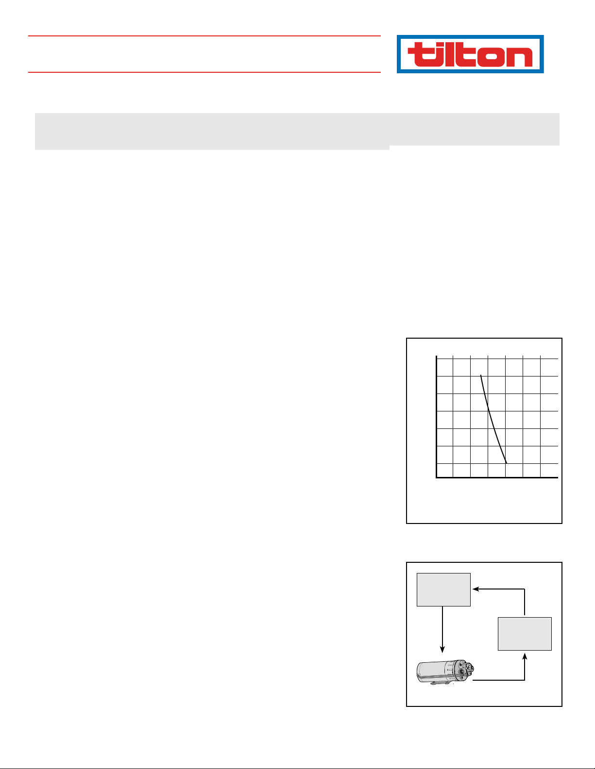
The Tilton Dierential Pump is a positive displacement type of pump, so its output is directly proportional
to the motor speed. If a lighter load increases the motor speed by 25%, then the ow rate increases by
25%. The ow rate vs. pressure is shown in Graph 1 with a maximum available pressure of 60 PSI. A uid
system will only ow as much as the smallest restriction will allow. Larger diameter lines and ttings allow
more ow and place less load on the pump. This pump is self-priming and can be placed up to 8 ft above
the source from which it draws. The typical application for the pump is in a dierential or transmission
cooling system. However, the pump can be used for other applications such as emptying fuel tanks. A 12-
volt DC, 10-amp power supply is required. The current draw is 6.6 amps under a maximum load condition
with a more typical current draw between 2 and 3 amps. This pump has a very light weight at 3.5 lbs and
has a ow rate of 1-2 gallons per minute. There are two types of diaphragms available for the dierential
pumps; the BUNA type diaphragms are for standard coolants and the VITON diaphragms are for the more
corrosive coolants.
InstallatIon notes
The Tilton Dierential Pump is placed inline with the cooling system as shown in Diagram 1. Placing the
pump on the outlet side of the cooler exposes it to lower temperatures signicantly increasing the life
and reliability of the pump. A 40-mesh (400 micron) strainer or lter placed inline before the inlet of the
pump prevents foreign objects from damaging the pump. Heavy gear oil must be brought up to oper-
ating temperature before the pump is engaged. The cold uid can be very thick and place an unusually
large strain on the pump. Tilton recommends the use of an on/o switch so the pump can be turned o
during warm-up periods. The pump includes an integral cooling fan to keep the pump cool during loaded
conditions. If the pump is mounted in a vertical position, mount the pump with the motor above the pump
inlet and outlet to prevent damage to the motor in the event of a uid leak. The pump head can be rotated
in 180-degree increments, allowing a variety of hose positions. Be careful not to damage the plastic pump
housing by over tightening the ttings. If a check valve is placed inline with the pump, the check valve
must have an opening pressure of no more than 2 PSI. The electrical hook-up is simple. Connect the pump
to a 12-volt DC supply with a 10-amp fuse inline with the (red) positive lead. The black lead is the chassis
ground.
PumP removal
1. Drain any excess coolant out of the pump before continuing
2. Disconnect the electrical connections
3. Disconnect the inlet and outlet lines
4. Remove the pump from the vehicle
Pressure (PSI)
Head-Flow Performance
70
60
50
40
30
20
10
0
0 1.0 1.5 2.0 2.5 3.0
.5
Flow Rate (GPM)
Graph 1
98 -19 01
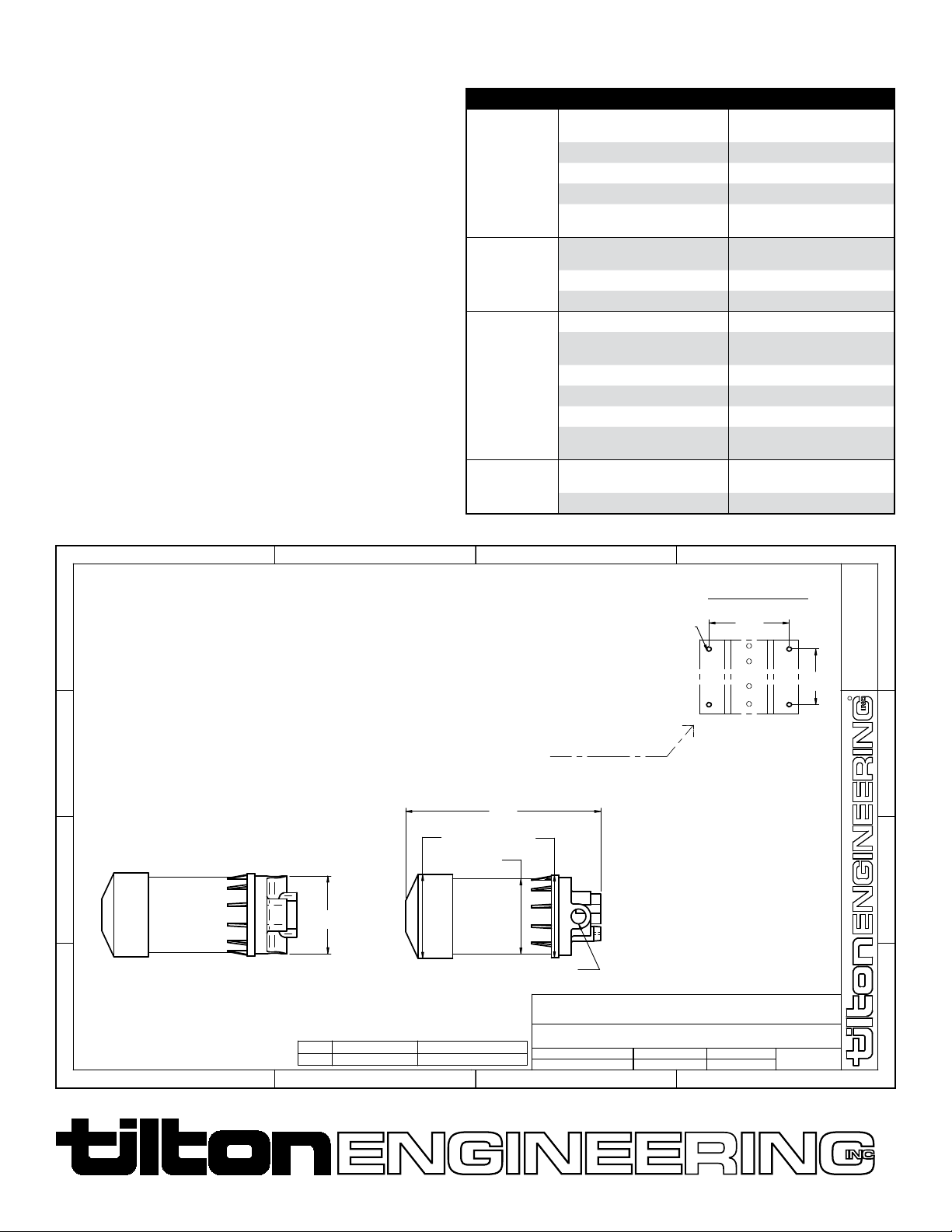
mountIng Hole DImensIons
• 2.25” vertical centers x 3.25” horizontal centers.
• Drill hole diameter: 3/16”, 4 places.
• Use high quality #10 bolts with lock nuts
PLUMBING
• For best results, use AN8 steel braided exible hose.
• Use only 3/8” NPT ttings at the pump inlet and outlet.
OPERATION
• Allow the pump to prime with the discharge line open to prevent airlock.
• The pump will not be harmed if it is allowed to run dry. It is self-priming.
ELECTRICAL
• Use a minimum of 16AWG stranded wire for power connections.
• Use a 10-amp inline fuse on the 12-volt DC (red) power connection.
Di /Trans
Cooler
Dierential
or
Transmission
Diagram 1
Page 2
CHeCk valve assembly rePlaCement
21
(Refer to Diagram 2 for the Part Numbers)
1. Mark a line at the joint between the pump head and the cam bearing
housing and use this line when assembling.
2. Pay particular attention to the orientation of the pump head inlet and
outlet lines and the check valve.
3. Loosen and remove the four upper Phillips head screws that retain the
pump head assembly.
4. Remove the pump head assembly.
5. Carefully remove and set aside the old check valve body, which
includes the old o-ring.
6. The Tilton Dierential Pumps (P/Ns 40-524 & 40-525) use the o-ring
that is supplied. The ring seal is not used.
7. Place the new o-ring into the new check valve body.
8. Insert the new check valve body with o-ring installed into the pump
head.
9. Place the pump head onto the cam bearing housing.
10. Align the marks that were made on the body in step #1.
11. Insert and tighten the four Phillips head screws.
12. Temporarily supply 12-volt DC power to the pump and check oper ation of
the pump before installing it into the vehicle.
Diagram 2
troublesHootIng
Symptom Possible Causes Action to Take
Motor runs,
no discharge
Motor fails to
turn on
Low ow and
pressure
Pulsating
ow-pumping
cycle on/o
Restric ted intake or
discharge lines
Air leak in intake line Check for leaks
Punctured pump diaphragm Disassemble and inspect
Crack in pump housing Inspect for cracks
Ensure correct power polarity
Pump or equipment not wired
correctly
Defective motor Check for motor rotation
Blown fuse or switch is o Check fuse and power
Air leak in intake line Check for leaks
Accumulated debris inside pump/
plumbing
Worn pump bearing Disassemble and inspect
Punctured pump diaphragm Disassemble and inspect
Defective motor Check for motor rotation
Insucient voltage to pump
Restricted pump delivery
Undersized line to intake of pump Use only 3/8” NPT ttings
Restric ted intake or
discharge lines
Check fuse, power switch
and polarity
Check fuse, power switch
and polarity
Disassemble and inspect
Measure supply voltage, must be
> 12-volt DC
Check discharge lines, ttings
for blockage
34
MOUNTING HOLE DIMENSIONS
SHEET OF
1
3.25
(82.55)
1
1
FAX 805/688-2745
: 1
DWG
5286
2.25
(57.15)
"This document contains proprietary information of TILTON
ENGINEERING, INC., and its receipt or possesion does not
convey the rights to reproduce, disclose its contents, or to
manufacture, use or sell anything it may describe. Reproduction,
disclosure, or use without specific written authorization of TILTON
ENGINEERING INC. is strictly forbidden."
R
D
C
7.9
(200.7)
3.4O
(86.4)
B
3.15
(80.0)
A
3.05O
(77.5)
3.35O
(85.1)
3/8 NPT, 2 PL.
TILTON ENGINEERING, INC.
25 EASY STREET, P.O. BOX 1787, BUELLTON, CA 93427 805/688-2353
TITLE:
40-524 COOLER PUMP, BUNA FOR NON-CORROSIVE FLUIDS
40-525 COOLER PUMP, VITON FOR CORROSIVE FLUIDS
DRAWN BY CHKD SCALE
P/N
Drill Hole O 3/16", 4 PL.
TRANSMISSION/DIFFERENTIAL OIL COOLER PUMP
AVAILABLE WITH BUNA OR VITON RUBBER DIAGHRAM
REED
SEE TABLE
DATE
02/22/08
25 Easy Street • Box 1787 • Buellton, CA 93427 • USA • (805) 688-2353 Fax (805) 688-9407
98 -1901
 Loading...