

Tilton Floor-Mount User Manual
INSTALLATION INSTRUCTIONS
900 Series Floor-mount 3 Pedal Assembly
Description
Minimizing friction and ex in the pedal assembly and the master cylinders maximizes driver
control. The Tilton oor mount pedal assembly with forward mounted pivot type master
cylinders eectively handles these critical issues. In addition this assembly is highly adjust-
able for dierent drivers and tracks, easy to install and maintain, and does all of this in a very
lightweight package.
Master cylinDer & peDal asseMbly installation
1. A pedal assembly can only be as rigid as its mounting system in the car.
Flex in the supporting structure reduces braking control as much as air in the lines. See the
drawing on page 4 for the mounting bolt pattern. Multiple holes in two tubes running fore/aft
in the car can allow multiple mounting positions.
2. Select the brake pedal pivot position (high or low motion ratio).
The overall pedal ratio is dependent on the pivot position combined with the foot pad
position, and the ratios are marked on the brake pedal. Tighten the four fasteners to
46 in-lbs using a 3mm hex wrench.
3. The balance bar clevises are of two dierent lengths; The longer clevis is to be used with
the master cylinder for the front brake system and should stay on the right-hand side of
the brake pedal. This conguration ensures the best remote adjuster cable clearance to
the throttle pedal.
4. Set the center-to-center distance on the two balance bar clevises at 2.60". A good place to
start is with both clevises equally spaced from the pedal (middle balance bar position).
5. Remove the long bolt that mounts the three master cylinders. Remove the four master
cylinder spacers from the frame.
6. Reinstall the two center master cylinder spacers in the frame. A small amount of RTV will
keep the spacers in place during assembly.
7. Install the master cylinders. It is best to install the master cylinders on the pedal assembly
before placing the assembly in the car. Reinstall the mounting bolt through the three
master cylinders, and tighten the nut to 120 in-lbs.
8. Thread the three pushrods into the clevises .710" (about seventeen (17) revolutions).
This will position the pedals as shown in the drawings. Final pedal position adjustment
will be made later.
9. Since the brake pushrods are threaded equal amounts and the clevises have two dierent
lengths, the balance bar will be at a 5˚ angle. This is by design and will be addressed in the
Pedal Positioning section.
10. Mount the pedal assembly into the car. Be sure to use high quality 5/16" or 8mm Allen
head bolts of the appropriate length with a supplied AN washer under the head of each
bolt.
Note: For clearance reasons, Allen mounting bolts must be installed with the
head recessed in the counterbore of the frame. Do not be tempted to use
a large OD washer and a hex bolt that will not sit in the counterbore of the
frame, as interference to critical moving parts will occur.
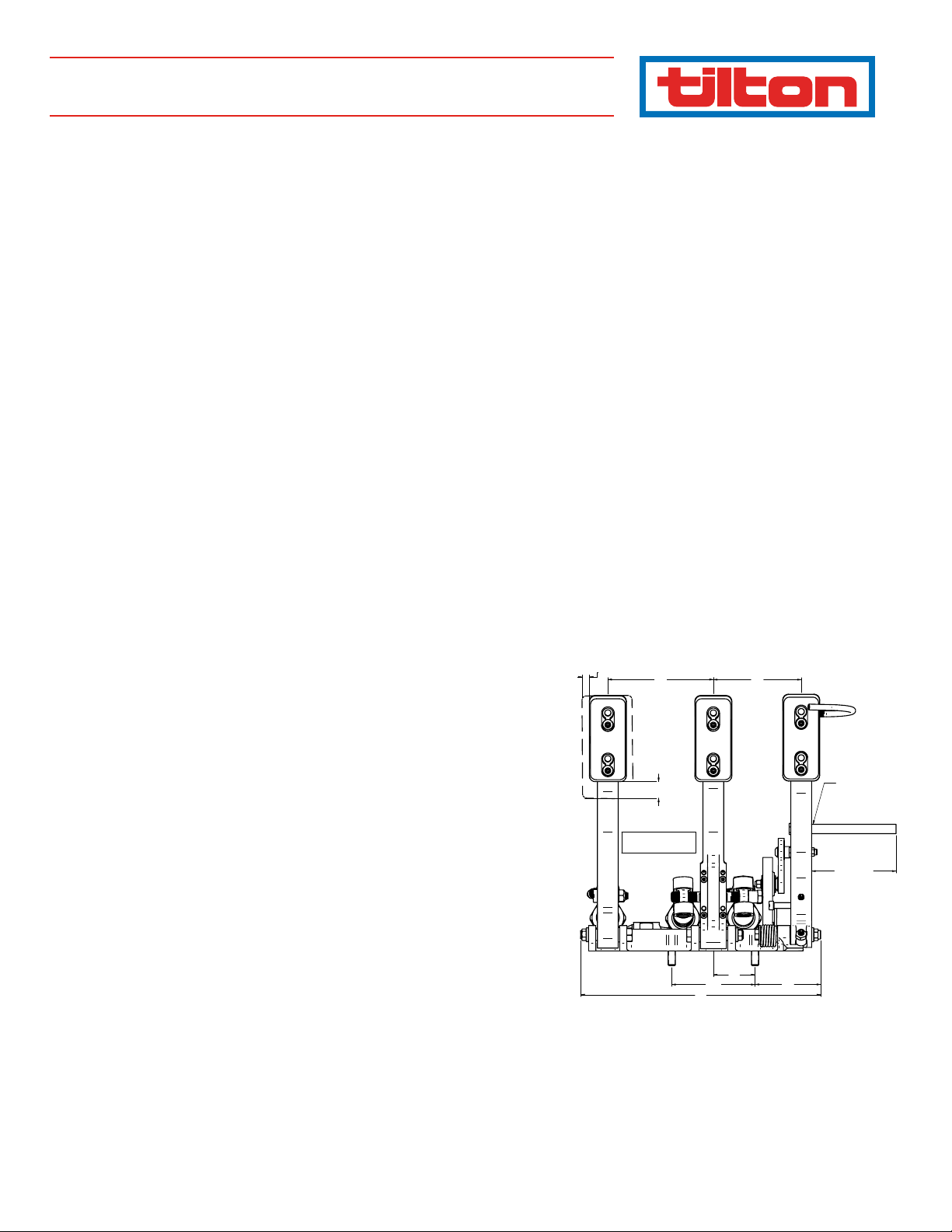
FOOT PAD SID E ADJUSTM ENT: THREE PO SITIONS, .290 INCREMENTS
4.56
ALL 3 PEDALS, .75 0 TOTAL
FOOT PAD HEIGHT ADJUSTMENT
FOUR POSITIONS, .250 INCREMENTS
BILLET AL UMINUM PEDALS ARE
OPTIMIZED FO R STRENGTH,
WEIGH T AND STIFFNESS
1.80
3.600
10.4
98 -12 0 7
3.80
THROTT LE CABLE STANDOFF
FOR REAR E NGINE CAR S.
UNFIN ISHED END C AN BE MODIFIED
BY CUSTOME R TO ACCEPT A
VARIETY OF C ABLE AT TACHMENTS
CUT TO LENGT H
3.65
AS SUPPL IED
2.84

peDal positioning
1. With the system properly bled, and the brake pedal depressed, the straight portion of
the brake pedal beam should be close to square with the master cylinder pushrods as
viewed from the side. To achieve this, adjust the brake pedal height by threading both
brake master cylinder pushrods in or out of the clevises equal amounts. Keep at least
.300" of pushrod threaded into the clevises. With the pedal depressed, check the driver’s
reach. The driver must not be stretching toes to reach the depressed pedal, and the knee
must be slightly bent. Open a bleeder screw and conrm that the driver can fully stroke
the brake pedal in event of uid boiling, or a brake line failure. Move the entire assembly
in the car if a coarse adjustment is necessary. Small adjustments in pedal position may
be made by threading the pushrods in or out of the clevises. Tighten the two pushrod
locknuts once the proper pedal position is achieved. The pushrod has two ats to accept
a 5/16" wrench.
2. The front master cylinder will require more stroke to operate than the rear once the sys-
tem has been bled. After bleeding, check to make sure the balance bar is parallel with the
rewall when the brakes have been applied with the normal wheel locking force. If not,
loosen the locknuts, readjust, and retighten the locknuts.
3. Thread the clutch master cylinder pushrod in or out until the desired pedal height is
achieved relative to the brake pedal. Keep at least .300" of pushrod threaded into the
clevis. Tighten the pushrod locking nut.
4. If your hydraulic release bearing requires the use of a positive stop, a stop threading into
the frame and a locking nut have been provided. See your hydraulic release bearing
instructions for adjusting the pedal stop.
5. Set the throttle return stop according to driver preference. If you are unsure, a good start-
ing point for the throttle is to have it even with the depressed brake pedal. This allows
a driver who is completing his braking maneuver with the right foot to quickly change
back to the throttle.
6. For rear/mid engine cars, modify the throttle cable stando on the right side of the
throttle pedal to accept your particular cable or linkage. For front engine cars, bell crank
P/N 72-791 is useful.
7. Set the throttle depressed stop so that the engine’s throttle is fully open without strain-
ing the cable or linkage. If an alternate amount of throttle pedal throw or progression is
desired, a wide variety of mounting holes on the pedal and P/N 72-791 can be selected.
8. The toe clip allows the driver to pull closed a throttle that would otherwise be stuck in the
open position. It also provides a rest to keep the driver’s foot well supported with high
lateral loading. It can be re-bent as desired, rotated up or down, and moved left and right
via the threaded portion. Position it so that it does not interfere with normal pedal use,
yet can be easily reached should the need arise.
9. The footpad positions can be adjusted left and right in three .29" increments. The foot-
pad position can be adjusted vertically in four .25" increments. The vertical bolt pattern
is oset, so, turning the pedal pad over allows four positions with only 2 bolt patterns.
Always use both mounting screws per pad and a removable thread locking compound.
5 THROT TLE
STANDOFF OR
BELLCRANK LINKAGE
MOUNTING POSITI ONS
2 POSITION
ADJUS TABLE
PEDAL RATIO.
ADJUSTABLE
THROTT LE
PEDAL RETU RN STOP
OPTION AL BELL-CRANK THROTTLE
LINKAGE ASSEM BLY P/N 72-79 0
FOR FRON T ENGINE CA RS.
FULLY ADJUS TABLE FOR T OTAL THROW
AND PR OGRESSION
77 SERI ES MASTER CY LINDER
SOLD SEPARATELY
5/8" TO 1" B ORE AVAIL ABLE
ADJUSTABLE THROTT LE
PEDAL STOP
 Loading...