

Page 1
INSTALLATION INSTRUCTIONS
700-Series Hydraulic Release Bearing (Acura/Honda)
Tilton's Acura/Honda hydraulic release bearing assembly installs easily into any late model
(92'-on) hydraulic transmission when converting to a Tilton 2-plate 7.25" Carbon/Carbon or
Cerametallic clutch. Carbon/Carbon clutches use assembly 61-772 and Cerametallic clutches
use assembly 61-777. These assemblies eliminate the stock mechanical release bearing link-
age, slave cylinder, and all of its components. The Tilton hydraulic release bearing is ideal
for racing and high performance use. Our release bearing components are machined out of
billet aluminum, which results in a higher strength and lighter weight design. Each hydraulic
assembly comes complete with hydraulic lines and ttings.
The hydraulic release bearing assembly is self-adjusting in that the bearing stays close to the
clutch spring at all times even though the spring changes position with clutch wear. There is
no extra return spring that pulls the piston back all the way to the bottomed position. In this
respect, the piston in the hydraulic bearing assembly works like the piston in a disc brake
caliper, returning only as far as forced. This is why with a Tilton Hydraulic Release Bearing
assembly the clutch pedal feel does not change with clutch wear allowing the driver to make
more consistent shifts.
INSTALLATION
1. Remove the original equipment (OE) from the front of the gearbox, including the release
fork, release fork pivot, and slave cylinder.
2. Apply a small amount of grease to the pilot nose to allow the o-ring located in the inter-
nal bore to slide on easily.
3. Install the Tilton bearing assembly onto the front of the gearbox so that both hydraulic
lines can be routed out the existing clutch release fork hole in the gearbox.
4. Insure that the assembly is seated ush with the bottom of the pilot tube.
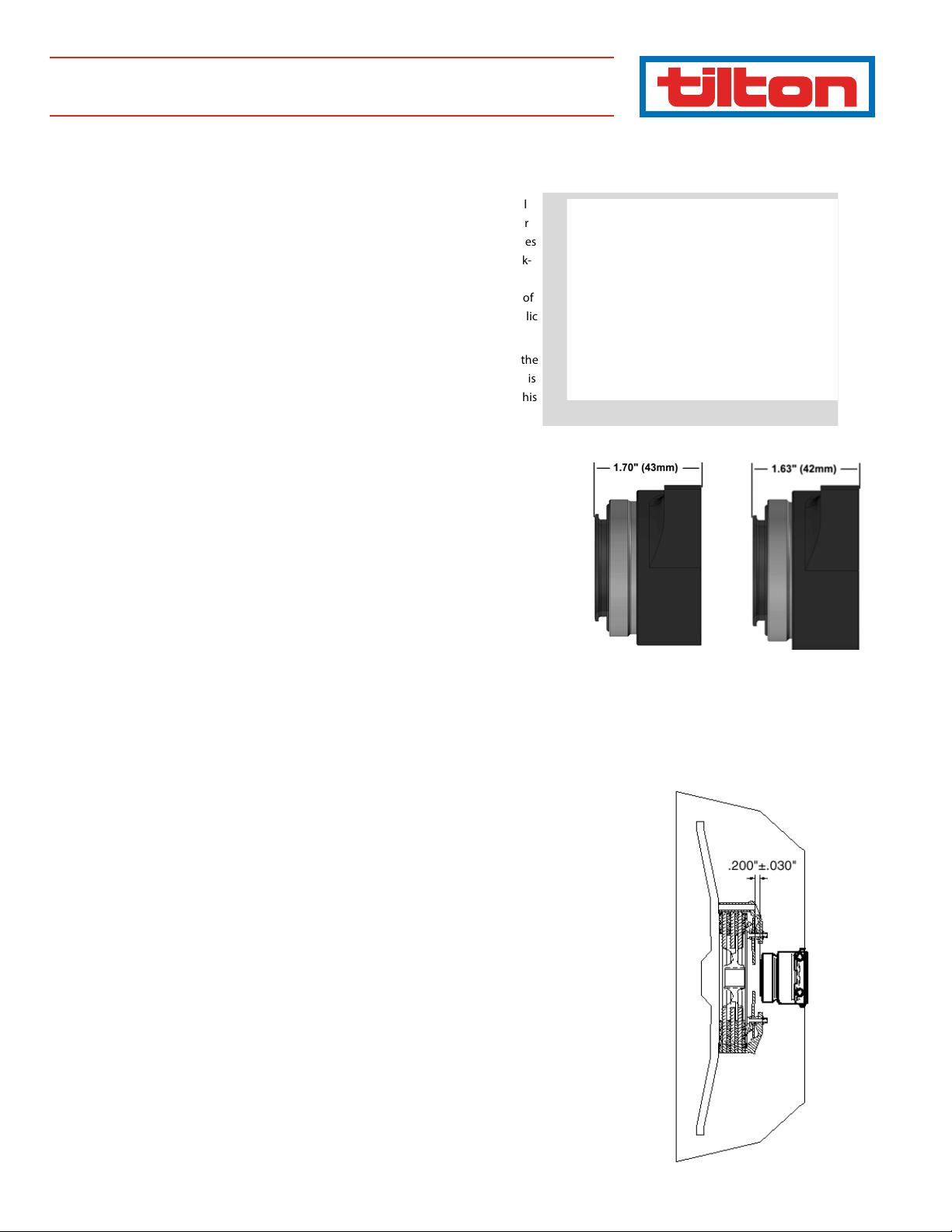
5. The heights of the installed assemblies are 1.63" for P/N 61-772 and 1.70" for P/N 61-777
when the piston is fully retracted as seen in Diagram 1. These heights are measured from
the bearing face to the ange mounting surface.
Note: The mounting surface is not the lower-most surface on the Honda
HRB's, it is the smaller ring recessed .100" from the bottom.
6. Please verify that there is approximately .200" clearance between the bearing face and
the clutch diaphragm spring upon installation, as seen in Diagram 1.
Note: Compression of the bearing piston into the bearing base, prior to
installation, to seat the seal may be required to achieve the set-up height
dimension.
7. A pedal stop must be installed on the clutch pedal to prevent over stroking the hydraulic
release bearing and damaging the clutch (see Pedal Stop section).
HYDRAULIC LINE INSTALLATION
Note: Fittings supplied in kit are -3AN 90˚ banjo ttings. It is important that
the crush washers used with the banjo ttings are replaced if the banjo ttings are removed from this hydraulic base. DO NOT use PTFE tape or thread
sealer. The single hydraulic line included in the kit is to be used to make both
the supply line and bleed lines.
61-772
(2-Plate Cerametallic)
98 -1115
61-777
(2-Plate Carbon)
Diagram 1
Page 2
SUPPLY LINE ASSEMBLY
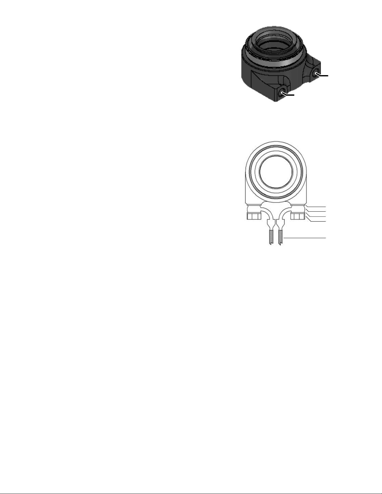
1. Assemble one of the banjo ttings with the supplied crush washers and banjo bolt
loosely onto the supply port of the hydraulic assembly (see Diagram 2).
Note: a crush washer needs to be placed on either side of the banjo tting
for proper installation.
2. Trial t the line in place and determine the length required for the supply line to reach
the master cylinder. Route the supply line clear of any obstructions to prevent damage
and away from heat sources to prevent pedal fade.
3. Cut braided line to length and attach ttings.
4. Leave the banjo tting loose for the supply line at this time.
BLEE D LINE A SSEM BLY
1. Assemble the second banjo tting with crush washers and banjo bolt and loosely place
the tting into the bleed port.
2. Trial t the remainder of the line, selecting a location for the bleed tting that is outside
of the transmission housing.
3. Thread the supplied bleed screw into the newly attached tting on the bleed line.
FINAL A SSEM BLY REFER TO DIAGRAM 3
1. With supply and bleed line assembled, clock banjo ttings inward, toward each other
leaving a small gap in between.
2. Tighten banjo ttings.
DRIVELINE ASSEMBLY
1. While installing the transmission, carefully route both lines through the release fork
window.
2. Once the transmission is seated, conrm that all parts of the release bearing and hydrau-
lic lines clear the clutch and ywheel.
3. Complete the driveline installation.
MASTER CYLINDER SELECTION
The recommended master cylinder bore diameter for use with this hydraulic release bear-
ing assembly and a 7.25" clutch is 3/4". If you are using the OEM clutch master cylinder,
please check the bore diameter.
MASTER CYLINDER PRIMING
1. Fill the master cylinder with brake uid. Use a DOT 3, DOT 4 or other non-silicone based
uid. Avoid DOT 5 (silicone based) uids since they are not compatible with the seals.
2. Open the bleed tting (if equipped) at the master cylinder while the line port is closed.
3. Gently depress the clutch pedal, close the bleed screw and release the clutch pedal.
4. Repeat Steps 1 and 2 until uid free of air bubbles emerges.
Do not stroke a Tilton master cylinder more than 1".
HYDRAULIC RELEASE BEARING BLEEDING
1. Fill the master cylinder reservoir with DOT 3 or DOT 4 brake uid.
2. Apply approximately 3 lbs of force on the clutch pedal. You want enough force to hold
the bearing out against the clutch diaphragm spring, but not enough to actually move
the spring.
3. Open the bleed screw that is attached to the bleed line on the hydraulic release bearing.
4. Completely stroke the pedal.
5. Close the bleed screw.
6. Let the pedal return to its relaxed position and wait a few seconds.
7. Repeat Steps 2 through 6 while keeping an eye on the uid level until all air is removed
from the system.
Note: You do not want to stroke the clutch during the bleeding process.
All you are trying to do at this point is get all of the air out of the system.
Do not stroke the clutch until the pedal stop is set!
Upper Port
(Bleed Line)
Diagram 2
Lower Port
(Supply Line)
Diagram 3
Crush Washer
Banjo Fitting
Crush Washer
Banjo Bolt
-3AN Line
Page 3

CLUTCH PEDAL STOP
A positive clutch pedal stop must be used to prevent over-stroking the
hydraulic release bearing piston and the clutch. For access reasons, in
many cars it is not easy to determine how far the master cylinder is being
stroked.
The method listed below provides a very eective method for adjusting
the pedal stop:
1. Lift the drive wheels o the ground and support the car on jack
stands.
2. With the engine o, place the gearbox in rst gear and have someone
attempt to rotate the drive wheels.
3. Depress the clutch pedal slowly until the clutch disengages and the
drive wheels can be rotated.
4. Adjust pedal stop to allow another 1/4" of pedal travel. This should
provide clean release of the clutch. Do not stroke the pedal any
further than this point throughout this procedure, otherwise you will
over-stroke the clutch.
MAINTENANCE
A few basic procedures will help to ensure that your hydraulic release
assembly will provide a long and dependable life.
1. Spin the bearing race and check how it feels. If it has a higher than
normal resistance or feels rough, replace the bearing.
2. The piston can be removed and replaced without breaking the
hydraulic seal or requiring bleeding. Periodically, remove the piston
and check for any scores in the bore or on the piston surface. Wipe
the piston and orange dust wiper seal before reinstalling. You may
nd that the piston is not dry. This could be the rubber grease used
when installing the new seal. Do not mistake this for brake uid.
3. If the seal needs replacing, order Tilton’s replacement seal kit (P/N
62-905). Instructions and the correct installation grease are included
in the kit. We also recommend the use of a seal installation tool (P/N
96-002) to prevent damaging the seal during installation.
SERVICE INFORMATION
1. Contact Tilton’s Repair Department (805-688-2353) and describe the
problem or the service that is required.
2. If the bearing assembly needs to be sent in, a Returned Merchandise
Authorization (RMA) number is required and will be provided by a
Tilton representative.
3. Write the RMA number on the outside of the package and ship to:
Tilton Engineering
25 Easy Street
Buellton CA 93427 hydraulic seal. Inspect the piston and
hydraulic assembly bore for scratches. To remove the hydraulic seal
from the release bearing assembly block one hydraulic port and
apply 5 PSI of air pressure to the other port. Wear safety glasses and
point the seal exit path away from you! Never try to pry the seal out
of the assembly. Refer to Diagram 7 when installing the new seals and
ensure that the at side of the main hydraulic seal rides against the
piston. Always use rubber grease, such as Tilton part number RG-17,
when installing the seal. Take care not to damage the seals during
installation.
FIREWALL
Adjustable
Pedal stop
Diagram 4
Pedal position where
pedal stop should be set.
Never travel clutch
pedal past this point!
Pedal position where
clutch breaks free.
1/4" additional travel
(exaggerated for clarity)
Diagram 5
Bearing
Piston
Main Seal
(Black)
Bearing
Base
Page 4

ECN
21
2.20
ENGINEERING INC. is strictly forbidden."
disclosure, or use without specific written authorization of TILTON
manufacture, use or sell anything it may describe. Reproduction,
convey the rights to reproduce, disclose its contents, or to
ENGINEERING, INC., and its receipt or possesion does not
R
"This document contains proprietary information of TILTON
4972
DWG
FAX 805/688-2745
2.25O
3/8-24 UNF
ACCEPTS BANJO (INCLUDED)
OR STRAIGHT FITTINGS.
2 PL.
1.70
1.94
1.80
.500
MAX STROKE
: 1
1
HONDA B/K SERIES, ULTRA SHORT
INSTALLATION DRAWING, HRB
CHAMBERS
1
1
SHEET OF
6/13/05
DATE
61-777
1.73O
ZONE CHKD DATE REV CHANGE OR ADDITION
44mm CONTACT DIAMETER
2.64
34
O 1.38
2.67
25 EASY STREET, P.O. BOX 1787, BUELLTON, CA 93427 805/688-2353
TITLE:
TILTON ENGINEERING, INC.
MAT'L
HARD
SPEC
COND
+.003/-.001
+.001/-.001
+.002/-.001
DRILL HOLES
.013-.040:
.041-.130:
TOLERANCES:
.020
.X ±
.010
.XX ±
.131-.229:
.005
1/32
.XXX ±
FRACT ±
UNLESS SPECIFIED OTHERWISE
P/N
DRAWN BY CHKD SCALE
SPEC
FINISH
+.004/-.001
+.005/-.001
+.007/-.001
.230-.500:
.501-.750:
.751-1.000:
1/2°
.005
(TIR)
ANGLE ±
CONC
NOTES:
D
C
B
A
Tilton Engineering, Inc. 25 Easy Street • PO Box 1787 • Buellton, CA 93427 • www.tiltonracing.com
1. DIMENSIONS IN INCHES EXCEPT WHERE NOTED.
2. MUST SET POSITIVE STOP ON CLUTCH PEDAL
PER INSTRUCTIONS.
 Loading...