

Tiltall BH Series, BH-10, BH-20, BH-30 Quick Start Manual
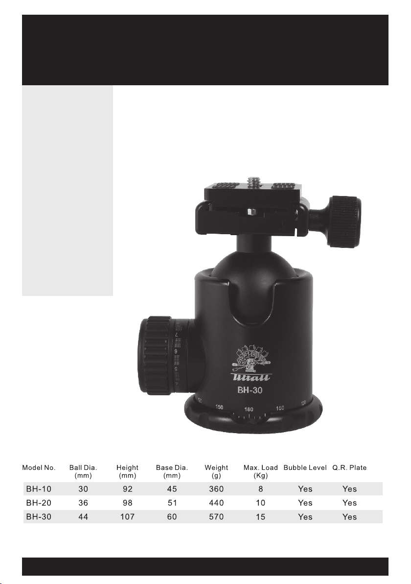
Tiltall BH Series Ball Heads
Center ball professional head
BH-10/ BH-20/ BH-30
Features incl ude:
• 30/ 3 6/ 44 bal l head wi th
qui ck rele ase pla te
air craft
• Mad e of alu minum
• Loc king kn ob with f ricti on
con trol
360 ° panni ng grad uated
•
sca le
• Qui ck rele ase pla te
wit h 1/4-2 0 screw
• Bui lt-in t wo bubb le
lev ers
A STRONG, DURABLE BALL HEAD
PERFECT FOR POINT-AND-SHOOT AND
DSLR CAMERAS.
Con tents : One bal l head, a nd a quic k relea se plat e.
www.t il ta ll tr ip od .c om
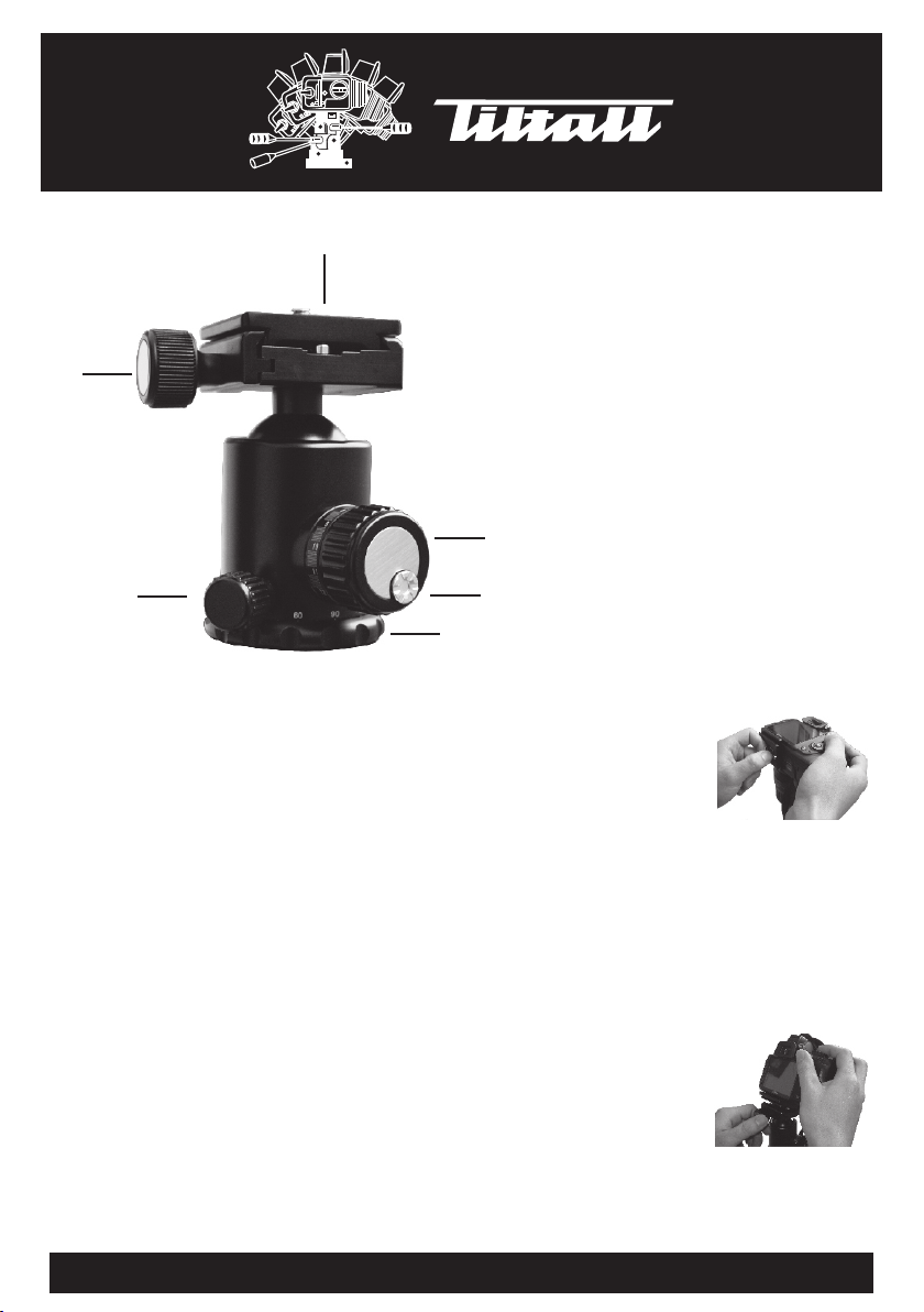
A
A: Quick release plate
B
C
Using The Ball He ad
The b all hea d is very c ompac t and eas y to use, a nd offe rs solid
cam era sup port wi th flui d smoot h movem ents. I t featu res a
sin gle bal l-loc king kn ob (D) wi th an adj ustab le drag c ontro l
scr ew (E), a nd a sepa rate pa n-con trol lo ck (C). T he calibrated
pan ning sc ale (F) a llows y ou to ref erenc e any mov ement s. Ther e
is a co nveni ent slo t on the ba ll head t hat all ows you t o chang e
you r camer a from ho rizon tal to ve rtica l forma t. To al ter the
pos ition o f your ca mera, s imply t urn the s ignal b all-l ockin g knob
cou nterc lockw ise. Th e further you turn th e knob, t he loos er the
fri ction o n the bal l becom es, all owing y ou quic ker and l arger
mov ement s.
You can i ncrea se or dec rease t he amou nt of fri ction o n the
bal l with th e adjus table d rag con trol sc rew. Fir st, tur n the sin gle
bal l-loc king kn ob (D) cl ockwi se to ful ly lock b all. Th en rotate the
adj ustab le drag c ontro l screw ( E) cloc kwise t o incre ase fri ction ,
or co unter clock wise to d ecrea se. Test yo ur setting by loosenin g
the s ingle b all-l ockin g knob. y ou may ne ed to rep eat thi s
pro cedur e to find t he desi red set ting wh en chan ging eq uipme nt.
Not ed: Always suppo rt the ca mera wh ile loo senin g the sig nal
bal l locki ng knob . Be sure t he sign al ball -lock ing kno b is full y
loc ked aft er sett ing the a djust able dr ag cont rol scr ew. Do not
ove rtigh ten kno bs.
B: Quick release clamp
locking knob
C:
360° panning locking
knob
D: Ball locking knob
D
E: Friction control screw
E
F
Attaching Cam era To The
Quick-Relea se (QR) Plate
Fir st remo ve the QR p late (K ) from
the h ead by ro tatin g the loc king kn ob
(L) c ounte rcloc kwise u ntil it s tops.
Mou nt the QR p late (K ) to the ca mera
by sc rewin g the 1/4 ”-20 ma le trea ded mou nt into t he came ra’s
bas e-pla te moun t using t he pop- up hand le on the u nder si de of
QR pl ate. Be fore fu lly tig hteni ng, be su re that c amera i s
par allel t o the pla te with t he lens s ide of th e camer a. When f ully
tig htene d, rota ting cl ockwi se the lo cking k nob aga inst QR p late.
Mounting Came ra To
The Ball Head
Wit h camer a facin g forwa rd, ins ert
the Q R plate u nder th e lip on th e
bal l head an d put dow n the cam era
the n rotat ing the l ockin g knob (L )
clo ckwis e until f ully ti ghten , holdi ng plat e in plac e.
To remo ve the camera from the bal l head, s imply r eleas e the
loc king kn ob coun tercl ockwi se unti l it stop s and, wh ile hol ding
the c amera s ecure ly in one h and, an d relea sed fro m head.
F: 360° panning scale
www.t il ta ll tr ip od .c om
 Loading...