

Tilia Maxi 80 - 200, CTC Maxi 80, CTC Maxi 100, CTC Maxi 120, CTC Maxi 140 Installation, Operating And Maintenance Instructions
...Page 1
161 505 07 02-01
Maxi 80 - 200
CAST-IRON BOILERS
TECHNICAL MANUAL
Installation, operating and maintenance instructions
EKSKLUZIVNI UVOZNIK IN ZASTOPNIK:
TILIA d.o.o., Lju bljanska c est a 89, 8000 Nov o m esto;
tel : 07/ 3324 442; fax: 07/ 3323 209; e-mail: info@ti li a.si; www.t ilia.si
Page 2

Page 3

A TTENTION!
The boilers in this series must keep
within the limits they are designed
for.
Any other use is to be considered
as improper and consequently
dangerous.
This limits are indicated on the
manufacturer´s data decal.
- Boiler type.
- Serial number.
- Max boiler power.
- Max boiler pressure.
- Max working temperature.
- Supply voltage.
• This manual is an integral and
esential part of delivery of the
boiler and must be given to the
User.
• If the boiler is transferred or sold
to other Users (change of destination or relocation)make sure that
the Installation, Operating and
Maintenance Manual is also
transferred so that it can be
consulted by the installer, the
maintenance technician and by
the new owner.
• Read the warnings and
procedures with care before
installing, filling or starting-up the
system and and before any
maintenance. The manual gives
important information regarding
system safety and protction of
DEFINITIONS
The terms A TTENTION, WARNING
and NOTE have been used when
draving up the manual to underling
instructions or information
that are considered to be critical
or unusual.
The conditions that dictate use of
these terms are defined as follows:
A TTENTION!
Information or procedures which
can cause danger situations if they
are not complied with.
WARNING
Information or procedures which can
cause damage to the machine or to its
components if they are not complied
with.
NOTE
Information or procedures which can
simplify or facilitate maintenance
procedures or important parts of the
text that need to be emphasised.
WARNINGS or REQUIREMENTS
This installation, Operating and
Maintenance manual is applicable for
all series
CTC Maxi cast-iron boilers designed to produce hot water (at temperatures below the boiling point and
atmospheric pressure) in central
heating systems.
Their operating pressure are up to 5
bar (test pressure: 7.5 bar).
Thermal power ranges go from 80 kW
to 200 kW.
1
persons.
• Installation must be done in
accordance with Current Law,
following the instructions given in
this manual.
Installation must be performed by
professionally qualified and
certified persons.
• Never permit the appliance to be
used or operated by inexpert
persons.
Erroneous installation or inadequate use and maintenance
of the boiler can cause harm to
persons or property for which the
manufacturer declines all
responsibility.
Page 4

Page 5

DEFINITIONS................................................1
1 TECHNICAL DATA
1.1 General characteristics..................................................4
1.2 Delivery contents............................................................ 4
1.3 Dimensions......................................................................5
1.4 T echnical data................................................................. 6
2 ASSEMBLY
2.1 Boiler assembly .............................................................. 7
2.2 Burner installation........................................................... 7
2.3 Insulation and shell installation...................................... 8,9
3 INST ALLA TION
3.1 Plumbing system............................................................ 10
3.2 Pipeline system standards............................................ 11
3.3 Heating water delivery and return pipelines................ 11
3.4 Safety , control and adjustment devices........................11
3.5 Water characteristics..................................................... 11
3.6 Electrical connections, system......................................12
3.7 Wiring diagram............................................................... 13
3.8 Heating plant................................................................... 14
3.9 Connection to the smokestack..................................... 14,15
4 OPERA TION
4.1 Control panel...................................................................16
5 SYSTEM START-UP, OPERATION
AND MAINTENANCE
5.1 Filling the heating system.............................................. 17
5.2 First start-up and preliminary checks........................... 17
5.3 Data for checking combustion...................................... 18
5.4 General boiler operating regulations............................18
5.5 Safety regulations and periodic checks.......................19
5.6 General maintenance standards.................................. 20
5.7 Inspection and maintenance......................................... 20
5.8 Checking hatchway seal................................................ 20
3
TABLE OF CONTENTS
Page 6

1. TECHNICAL DATA
1.1GENERAL TECHNICAL
CHARACTERISTICS
CTC Maxi cast-iron boilers are high
efficiency (superior to 90%) generators
of hot water up to 90°C for central
heating. The high efficiency of this type
of system also achieves extremely
LOW NOx emission to the atmosphere.
When LOW - NOx burners are installed
this boiler meets the most restrictive
European air pollution Standards.
The boiler body (made of modular castiron wet-chamber components)
functions in depression for the entire
range of admissible power ratings.
The boiler body is composed of:
a. Front component with inspection
hatchways and support for the
blown-air burner.
b. Intermediate elements with
shapes designed for high thermal
exchange even when operating at
LOW temperatures.
The number of elements can vary
depending on the thermal
capacity of the boiler.
c. End element that connects to the
delivery and return pipelines and
to the smoke exhaust system.
4
All elements are connected together
by twin-taper connection nipples.
Structural rigidity is achieved by tierods, which also function to carry loadbearing parts of the shell. Boiler
insulation is obtained by a thick layer
of glass wool applied directly to the
boiler body and the rear element. The
shell, made of stove enamelled steel
sheet, is quite simple, efficient and
modular and permits access to
inspection and maintenance
hatchways by simply removing
(without any tool) the front panel. The
shell also covers and protects the
control board which is furnished tested
and already wired.
Specific boiler data are given on the
data-decal applied to the back section
of the right side.
1.2 DELIVERY CONTENTS
Delivery consists of 6 packages:
1 - Pallet with boiler components
.
2 - Box with putty for seals between
modular component surfaces.
Putty applicator and twin-taper
connection nipples.
3 - Tie-rods for assembly .
4 - Box containing the front
hatchways, the hinge for the
lower door, front plugs,
connection flanges and seals,
sheath for control instrument
probes and baffles.
5 - Box containing the shell,
insulation, spacers for positioning
the shell, installation screws,
nuts and washers, technical and
guarantee documents.
6 - Box containing the control panel,
complete
7 - Assembly tools for boiler body
assembly (optional equipment)
Page 7
1. TECHNICAL DATA
5
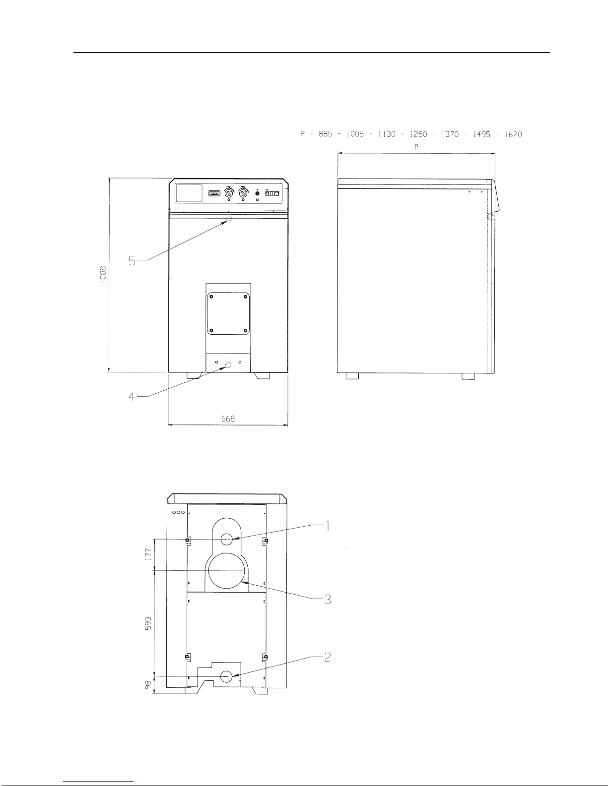
1.3 DIMENSIONS
1. Heating flow
2. Heating return
3. Flue gas connection
4. Drain
5. Sensortube
Page 8
6
1. TECHNICAL DATA
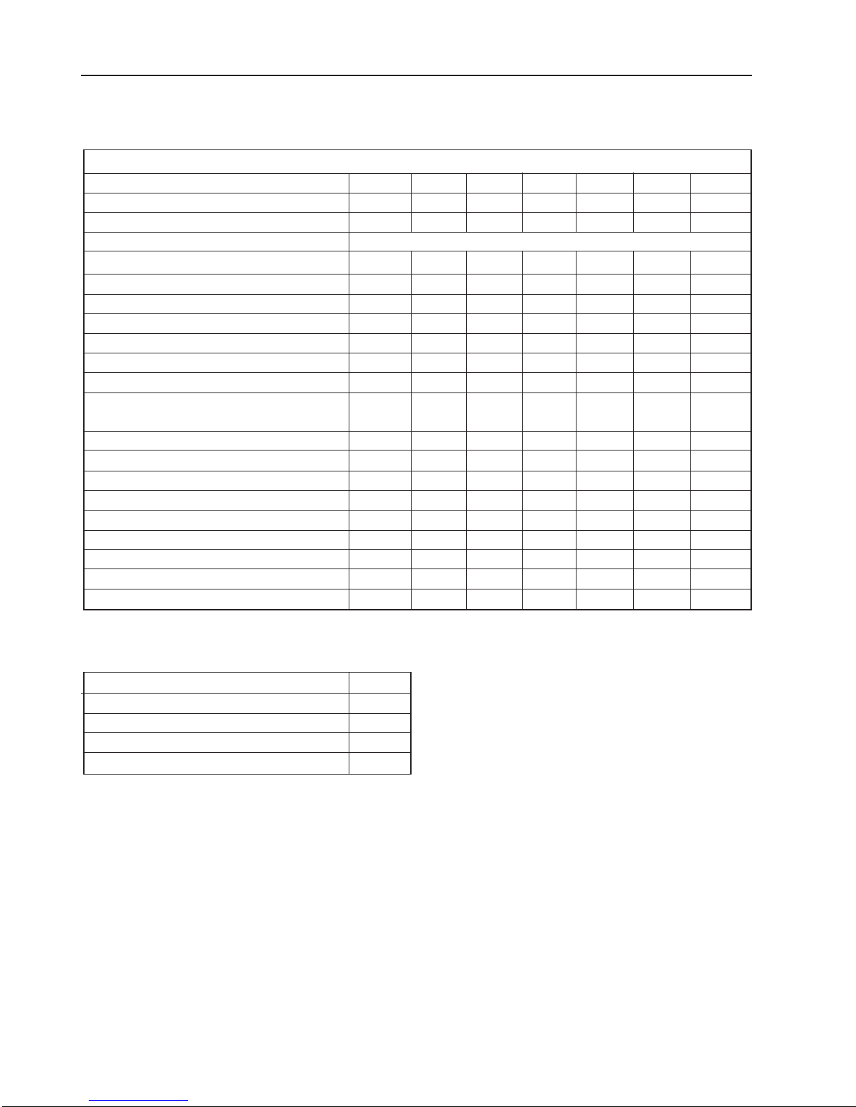
BOILER CTC Maxi80100120140160180200
Number of elements 6 7 8 9 10 1 1 12
Max output power kW 80 10 0 12 0 14 0 16 0 18 0 200
Max input power kW 88,9 1 11,1 133,3 155,6 177,8 200,0 222
Fuel Gas/Fuel-oil
Working efficiency % 90,0 90,0 90,2 90,4 90,4 90,5 90,6
Efficiency at 30% capacity % 88 88 88 88 88 88 88
Loss at the smokestack % 8,4 8,2 8,4 8,4 8,2 8,2 8,2
Smoke temperature* °C 205 20 0 202 202 200 20 0 20 0
Gas smoke flow rate kg/h 13 7 171 206 240 274 309 342
Fuel oil smoke flow rate kg/h 13 1 165 198 231 264 297 33 0
Smoke load losses mbar 0,10 0,15 0,28 0,30 0,40 0,55 0,66
Dimensions of the combustion chamber:
Length mm 565 686 807 928 1049 1 170 1291
Diameter mm 380 380 380 380 380 38 0 380
Volume of the combustion chamber dm
3
72 86 101 116 131 145 159
Smokestack connection mm 200 20 0 200 2 00 20 0 200 200
Water contents l 66,0 76,5 87,0 97,5 108,0 118,5 129,0
Water side load loss Dt = 15°C mbar 9 12 18 28 35 45 60
Delivery connection “G 2 ½” 2 ½” 2 ½” 2 ½” 2 ½” 2 ½” 2 ½”
Return connection “G 2 ½” 2 ½” 2 ½” 2 ½” 2 ½” 2 ½” 2 ½”
Boiler depth P mm 8 85 1005 1 130 1250 1370 1495 1620
Weight of empty boiler kg 41 0 465 520 57 5 63 0 68 5 740
* with CO2% = 13 for Fuel Oil and 10 for Gas
Max. operating pressure ba r 5
T est pressure ba r 7,5
Control thermostats ° C 21-85
Safety thermostat °C 1 10
Code PIN CE 0063/ ...
1.4 TECHNICAL DA T A
Page 9
2. ASSEMBLY
7
2.1 BOILER ASSEMBLY
(see the instruction manual
for boiler body assembly)
– The boiler must be installed so that
distances from boiler room walls
comply with the minimum
distances required by building
codes. Distances, in any case,
must guarantee easy access to the
boiler for maintenance
– The support surface for the boiler
must be horizontal.
– Pipelines that go to boiler
connections must be supported
and placed so that they do not bring
dangerous forces to bear on the
connections themselves.
– Connections for the two hoses to
the burner must be fastened in the
most convenient position for freely
opening the burner support plate.
– Ventilation must correctly furnish air
to the burner. Incoming fresh air
from below and evacuation of stale
air from the top part of the boiler
room.
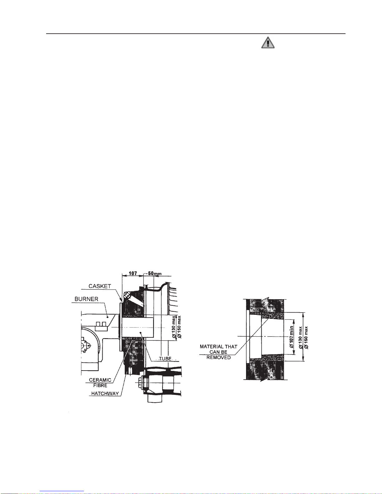
FIG. 2 - Burner installation diagram
2.2 BURNER INST ALLA TION
1- An installation counter flange for
the burner is installed on the
lower front door , which has to be
adapted to the tube and to the burner flange (figure 2).
2 -If the burner flange does not fit this
flange then an adaptation flange
and ceramic fibre gasket must be
installed.
3 -The tube diameter can be different
from the diameter of the hole in the
insulation. If necessary , the hole
in the insulation can be enlarged.
4 -Use a cutter to remove excess
insulation. Insulation is made of
ceramic fibres and can be cut by
normal cutting tools.
5 -The maximum hole diameter that
is admissible is 130/150 mm.
ATTENTION!
1 -The seat of the tube must be as
precise as possible to prevent
backfires or backflow of heat
which could scorch the burner
connection plate.
2 - If hole enlargement is
imprecise or if the hole (for easy
installation) is oversized then
the space between tube and
insulation or rough-cut edges
must be carefully and totally filled with ceramic fibre after the
burner is installed.
3 -If an adaptation flange is also
installed, make sure that smoke
seals are installed on both
couplingsurfaces.
4 - Lubricate burner anchor screws
with graphite to make
subsequent removal easier.
Page 10
2. ASSEMBLY
8
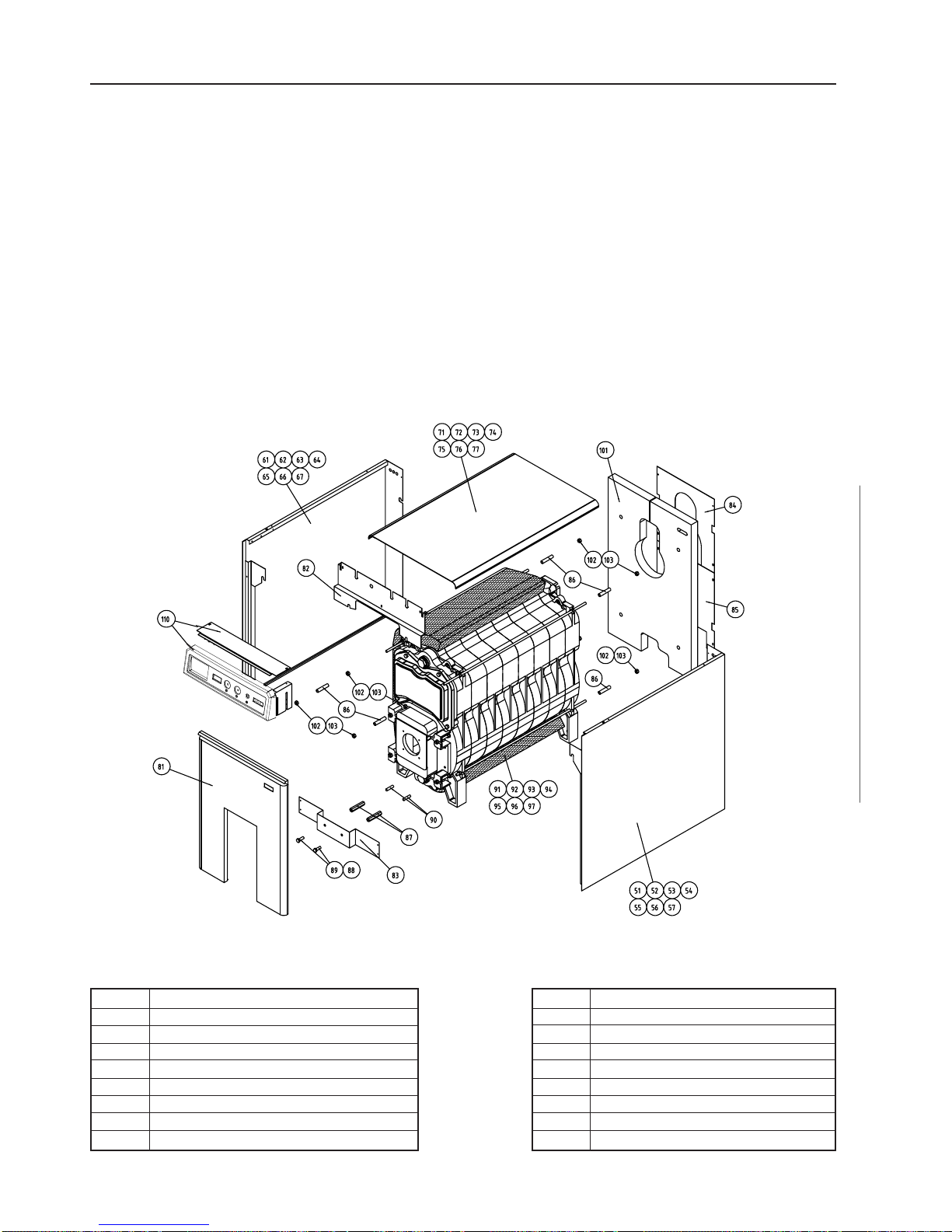
Legend
51 -57 Right side with from 6 to 12 elements 87 M10 threaded 17x95 hex spacer
61- 67 Left side with from 6 to 12 elements 88 D10 washer
71- 77 Cover with from 6 to 12 elements 89 M10 x 20 hex head screw
81 Central panel 90 M10 stud bolts
82 Top front bracket 91- 97 6 to 12 elements of mineral wool
83 Sheet metal strip 10 1 Rear section mineral wool
84 Top rear panel 102 M12 hex nut
85 Bottom rear panel 10 3 D12 washer
86 Spacer L=80 mm 3/8 tube 1 1 0 Control panel complete
2.3 INSULA TION AND SHELL INST ALLA TION (fig. 3)
NOTE
1 -This section describes,
in sequence, the operations
required for installing the
insulating mattress and the shell.
2 -Just a few easy to find tools are
required to install the shell.
Make sure tools are of good quality
and are not damaged or worn.
3 -The component numbers given in
the figure are indicated in order of
assembly and are used for the
entire description.
4 -Perform installation procedures in
the order that is given.
Check, before moving on to another
phase, that the previous phase has
been totally and correctly
performed.
FIG. 3 – Shell components
Page 11

6. Carefully unroll the capillary tubes
for the temperature sensors and
thread them into the sensor sheath
on the rear element.
7. Remove the instrument control
panel cover and make electrical
connections as illustrated in fig. 4.
ATTENTION!
1. Run the control panel, circulation pump and (if present) room
thermostat connection supply
cables through the cable glands
on the rear part of the side panel
and on the wall of the bracket
that also acts as the rear of the
instrument casing.
2. Connect the ground wire to the
connection terminal board( ).
3. Carefully check the ground
connection.This con nection is
obligatory and must meet CEI
standards and requirements.
The manufacturer will not be
responsible for damage to persons or property caused by failure to comply with this basic
requirement.
SHELL INST ALLATION
1. Install the bracket (82), placing it
on the upper tie-rods in the front
section, fastening it with nuts and
washers (102.103).
Subsequently install the six
spacers (86) (4 on the rear side
and 2 on the top front side).
2. Centre the insulating mattress
(91÷97) in place on the boiler body,
fastening it with the strap.
3. Install the right (51÷57) and left
(61÷67) side panels, making sure
their connection slots mesh on the
extensions from the tie rods.
Also, make sure that the spacers
(86) are inside the panels. Fasten
the sides to the bracket (82) using
self-tapping screws.
4. Install the 2 M10 stud bolts (90),
positioning them in the two holes
near the lower hub. Screw the
two threaded hex spacers (87) on
these. Now install the lower sheet
metal strip (83) and fasten it to the
sides using self-tapping screws
and in the centre by letting the hex
head screws (89) rub up against
the threaded spacers.
5. Insert the control panel (110) in its
seats and fasten it to the side
panels using self-tapping screws.
2. ASSEMBLY
9
8. Reinstall the top panel on the
control panel cover.
9. Install the top cover (71÷77),
centring the holes on the
retaining pins.
10.Fasten the sides to the tie-rods
by tightening the nuts and
washers (installed at phase 3.
above). Do not use excessive
force.
1 1.Install the front panel (81), cent-
ring the retaining pins with the
clamps.
12.Fully tighten the central screws
on the lower sheet metal strip.
(installed at phase 4. above).
IMPORT ANT
The data-decal must be applied
once the shell has been installed.
The data-decal, furnished with the
boiler casing, is installed on the top
rear corner of the right side panel.
Page 12
3. INSTALLATION
3.1 PLUMBING SYSTEM
Important
Installation must be performedby technically qualified personnel.
10
Applicable installation standards are
for boilers in heating systems that
use pressurised hot water with
temperatures below the boiling point
at atmospheric pressure.
WARNING
CTC Maxi boilers have a
maximum 5 bar operating
pressure.
Consequently , make sure that the
hydraulic pressure measured
downstream from the pressureregulating valve on the supply
pipeline is not greater than this
0
10
20
30
40
50
60
70
80
4000 5000 6000 7000 8000 9000 10000 11000 12000
W ATER FLOW RATE (Kg/h)
LOAD LOSSES (mbar)
CTC Maxi boiler water load losses
pressure.
Also, check that this maximum
pressure is not exceeded when the
heating system is at operating
temperature.
Check that boiler relief valve drains
are correctly connected to drain pits.
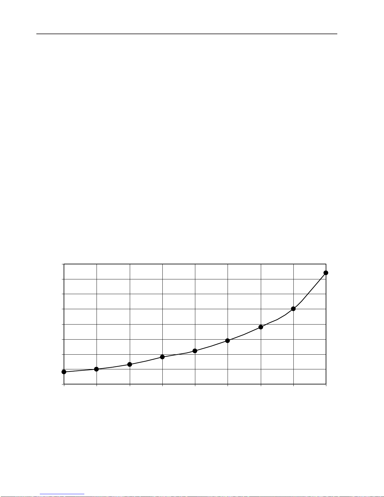
Boiler load losses are indicated in
the following chart, in function of the
flow rate of water in circulation.
Page 13

3. INSTALLATION
11
3.2 PIPELINE SYSTEM
ST ANDARDS
1- The weight of connection pipelines
and the forces generated by
thermal expansion must not bear
on the boiler and subject flanges
and screws to stresses, which
could, with the passage of time,
cause problems with seal or
breakage.
2- If pipelines are long, they must be
equipped with expansion joints,
zigzag elbows, etc.
3- Hot pipelines must be insulated to
prevent heat losses. Leave
pipelines exposed only where they
require periodic inspection
(flanges, expansion joint
connections, branches, etc.).
Insulation must be performed in
accordance with existing codes
and regulations).
4- It is good practice to furnish the
system with a drain cock. Y ou can
use the plugged hole on the rear
element for this purpose.
3.3HEA TING WA TER DELIVERY
AND RETURN PIPELINES
a- Install two on/off valves when
connecting the boiler to the heating
system pipeline network. This
makes it possible to isolate the
boiler from the rest of the heating
system.
3.5 WA TER CHARACTERISTICS
The chemical and physical characteristics of pipeline system and refill
water are key factors for system
security and proper boiler operation.
It is well known that poor quality water
creates problems for the entire system. The most common but also the
most important phenomena is the
deposit of scale on the heat exchange
surfaces. This scale, even if it is very
thin, has LOW thermal conductivity and
insulates boiler walls. These are no
longer cooled by recirculating water
and are consequently subjected to
overheating that causes irregular
thermal expansion and localised
thermal shock. Inquire of specialised
water treatment companies to set up
suitable automatic water test and
treatment systems. Water treatment
is necessary when: pipeline systems
are very large; the available water
supply has very hard water; whenever
the system must be partially or totally
emptied, for whatever reason, and then
refilled.
b- On/off valves, when installed, must
be placed so that they do not
exclude safety components when
they are activated (pressure
switches, block thermostat, relief
valve/relief pipeline, etc.). The
entire installation, in any case,
must correspond to current
regulations.
c- Avoid creating points where air
bubbles can form and stagnate
when designing and installing the
pipeline system. If this cannot be
avoided then install automatic air
bleed valves or bleed pipelines that
drain to the ground and that have
easily accessed manual control
valves.
3.4SAFETY , CONTROL
AND ADJUSTMENT DEVICES
These must conform to current
regulations. Maximum hydrostatic
pressure must not exceed the maximum operating pressure indicated
on the name-plate.
A TTENTION!
An insufficient-water detection system must be installed in roofmounted heating plants; meaningheating plants where partial
emptying of the pipeline system
could cause irreparable harm
before it is detected.
Required water characteristics are:
Fill and refill water
Appearance clear
Max. total hardness 20° F
Max. free oxygen 0,0005 mg/l
Max. organic matter 0,5 mg/l
min. pH 8,5
Page 14

3. INSTALLATION
12
3.6 ELECTRICAL CONNECTIONS/
SYSTEM
1. The boiler’s electric board must
be powered with single-phase
230V/50 Hz current plus a ground
cable.
2. When connecting supply cables
to the terminal board make sure
the ground cable is longer than
the line and neutral cables so
that it is the last to be
disconnected in case the wires
are torn off.
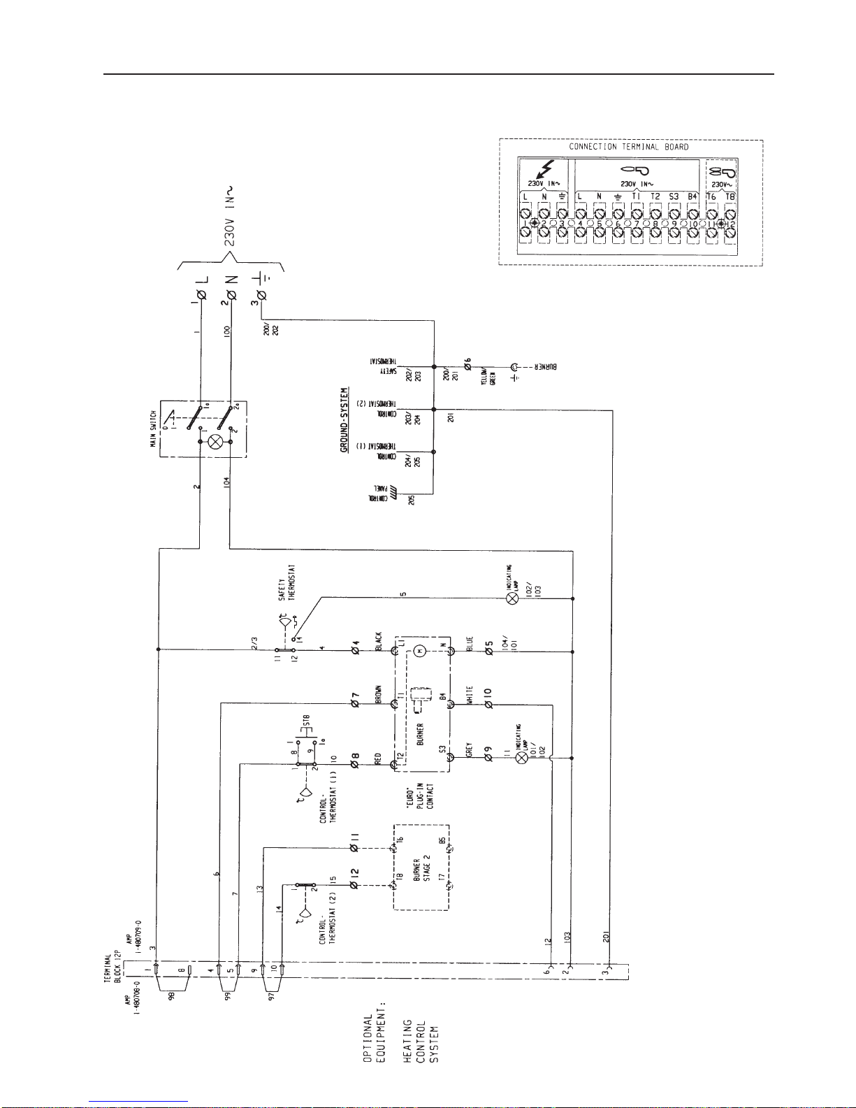
3. Refer to the wiring diagram in
figure 3.7 to make connections.
4. Have professionally qualified
personnel check the system and
make sure it is properly sized for
the maximum power absorbed by
the appliance and that the ground
connection is efficient and
complies with CEI standards.
ATTENTION!
1. Ground resistance, in Ohms,
must comply with CEI
standards. The Manufacturer
declines all responsibility for
accidents or harm to persons
and property caused by failure
to comply withthis fundamental requirement.
2. Make sure the burner can only
function when at least one
water circulation pump is
functioning.
3. The control panel supply
cable must be placed inside
the shell above the insulating
mattress and must exit
through one of the cable glands
provided
(see SHELL INST ALLA TION).
5. The main power supply to the
appliance cannot be through
extension cords, adaptation
sockets or multiple jacks.
6. Connections to power mains
must be through a two-pole
switch with at least 3 mm contact gap. This functions as an
isolating switch to isolate the
boiler from the rest of the
electric system.
ATTENTION!
Use of any electrical component
requires compliance with a few fundamental rules and regulation such
as:
a) Never pull on, twist or cut
electric cables;
b) Never permit inexpert persons
to use the appliance;
c) Protect outdoors-electrical
equipment from weather (rain,
sun, fog, etc.).
The electrical system must conform
to current regulations.
In particular a proper connection to an
efficient ground system must be made
according to CEI standards.
A TTENTION!
The manufacturer is not
responsible for damage to persons or property caused by an
inadequate ground system
Have the electric system checked by
professionally qualified personnel
who certify that it conforms to the
boiler’s maximum absorbed power.
Page 15
13
3. INSTALLATION
3.7 WIRING DIAGRAM CTC MAXI 80-200
Page 16

14
3. INSTALLATION
3.8 HEA TING PLANT
The heating plant must comply with
current standards and regulations.
3.9 CONNECTION TO THE
SMOKEST ACK
The boiler must be connected to an
efficient and independent smokestack
with a size calculated according to the
thermal capacity of the boiler, the
height of the smokestack and the type
of fuel being burned. The smokestack
must be perfectly hermetic and have
insulated smooth walls.
The connection between boiler and
smokestack must be the same size
as the connection to the boiler. It must
slope upward 5%. If it is longer than 1
meter then it must be insulated in
accordance with the safety regulations
called for by safety standards.
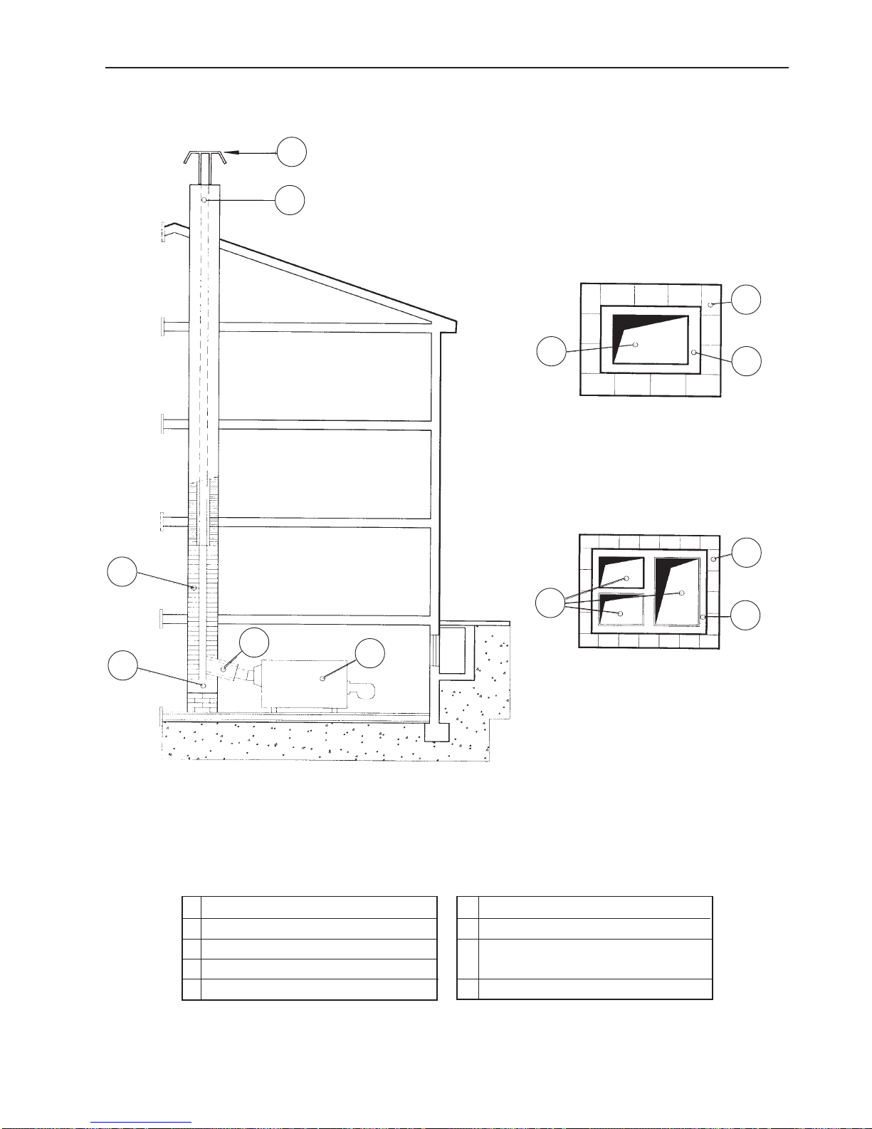
Figure 5 illustrates the best structure
for a smokestack.
Insulation is necessary to prevent
excessive cooling of smoke. If the
temperature of products of combustion
drops below 160°C this creates
condensation of carbon residue that is
expelled in the atmosphere.
Condensation can also take place
even on perfectly insulated smokestacks with high thermal inertia. This
is caused by repeated burner ignition
and stoppage at short intervals, which
does not give the smokestack time to
reach and maintain ideal temperatures.
We recommend installing lightweight
smokestacks with LOW thermal inertia
and with compact cross sections that
are not oversized.
Page 17
15
FIG. 6 – Structural characteristics of smokestacks
1 Boiler 6 Masonry
2 Smokestack connection 7 Mineral wool cladding
3 Refractory brick 8 Smokestack made of prefabricated
4 Ash collection bin parts with LOW thermal inertia
5 T op end of the smokestack 9 Rain cap
3. INSTALLATION
9
5
Single smokestack
Multiple smokestacks
"A"
"B"
6
7
8
6
7
8
2
1
4
3
Page 18
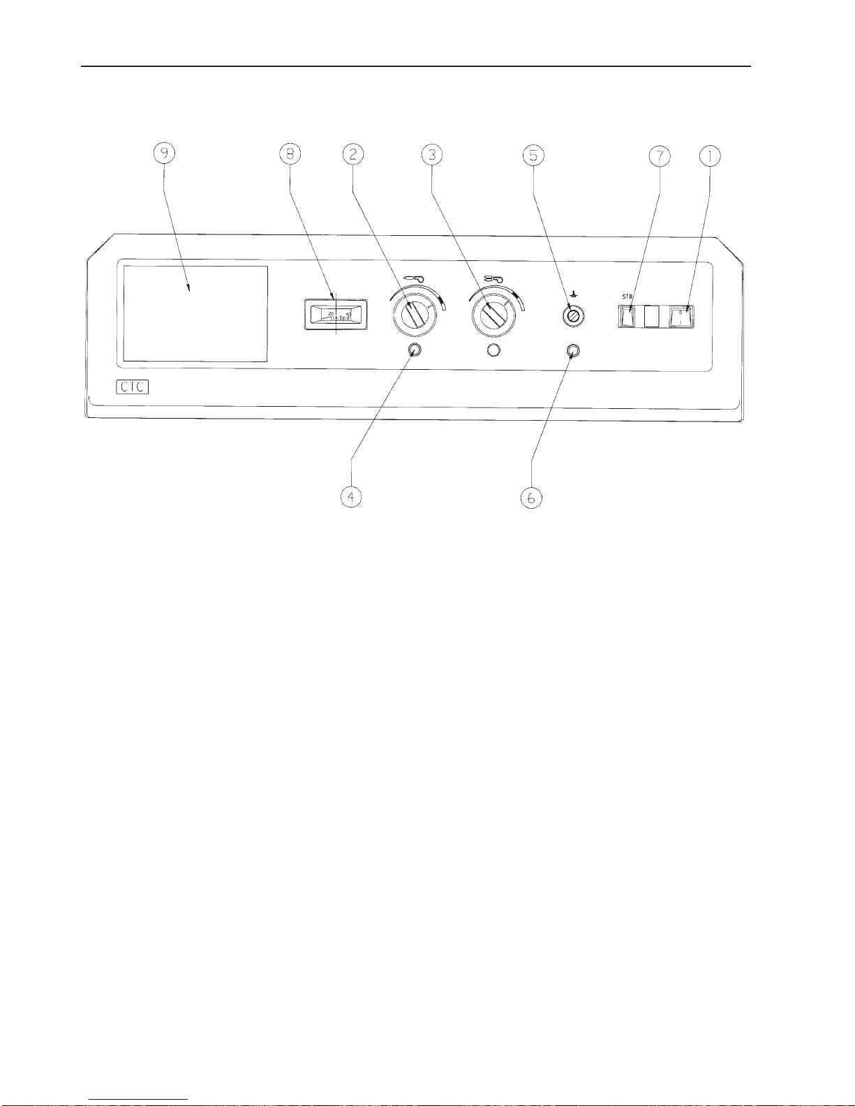
16
4. OPERATION
1. Mainswitch
A green lamp lights when power
is on.
2. Control thermostat,
burner stage 1
For adjusting the boiler temperature up to 85°C. Recommended
temperature is marked at the
scale.
3. Control thermostat,
burner stage 2
For adjusting the boiler temperature. Recommended temperature
is marked at the scale.
4. Indicating lamp
burner lock-out
5. Safety thermostat
The safety thermostat disconnect
the electrical power if the boiler is
overheated. Reset by pushing the
button which is under the cover,
when the boiler temperature is
below 65°C
6. Indicating lamp
safety thermostat
7. STB-switch
Used by serviceman to check the
safety thermostat
8. Boiler thermometer
9. Heating control (Option)
4.1 CONTROL PANEL
Page 19

17
5. SYSTEM START-UP, OPERATION AND MAINTENANCE
5.1 FILLING THE
HEA TING SYSTEM
After installing the burner:
a- Check that the drain cock is
closed.
b- Open the pipeline system gates or
supply valves.
c- Check that the sealed expansion
tank is pressurised.
d- Manually open the mixing valve half
way (if it exists).
e- Fill the heating system with the air
bleed valves open. Close the valves
when only water comes out from
them, with no sign of air.
f - Check that the heating system
circulation pumps and the
recirculation pump rotate in the
proper direction.
g- Check for air in the system by
opening the highest bleed valves in
the pipeline system.
h- Check the pressure in the system
on the pressure gauge.
i- Check that the smokestack
damper is open.
5.2 FIRST START-UP AND
PRELIMINARY CHECKS
a- Set the boiler thermostat at
approximately 80°C.
Note
The manually reset safety
thermostat is already set at110°C.
b- Start the system circulation and
boiler recirculation pumps, making
sure water actually moves both in
the pipeline system and in the
boiler.
c- Start the burner and adjust it as
described in its operating manual.
d- Check that thermostats and control
gauges and instruments function
properly .
e- Check that the connection between
boiler and smokestack is perfectly
sealed. Any leaks must be sealed
off with glass fibre cord and high
temperature putty .
f - Check that front hatchways are
perfectly sealed. Check, in
particular, that flange and burner
tube seals are perfect and do not
permit any smoke to leak out.
NOTE
If there are small leaks around
the hatchways, these are
eliminated by regulating the
pressure on the gasket. Do this
by adjusting the nuts that clamp
the hatchways in a criss-cross
tightening pattern until the
defect is eliminated.
g- Check that there is sufficient draft
at the connection to the smokestack. There must be a depression
(at least -1÷ -2 mm H2O) at all
points in the smokestack and in any
flues when the boiler is operating
at normal levels.
h- Check that the sealed expansion
tank functions correctly . Check, in
particular, the settings of its safety
valves.
i- Check for and eliminate the cause
if there are continuous changes in
pressure and consequently
continuous topping-ups with water
(leaks in the pipeline system, insufficient expansion tank volume,
etc.).
j- Check that there is no residual fuel
or foreign matter inside the
combustion chamber and that the
ceramic fibre insulation is not
damaged.
k- Check that the burner flame is
adjusted so that it does not contact
the walls of the combustion
chamber. This ensures proper
combustion and prevents damage
to the boiler body .
l- The water temperature in the boiler
must be between 50 and 85°C. The
difference in water temperature
between heating system delivery
and return must never exceed 20°C,
not even at the start.
m- Check for system seal when the
heating system is hot.
The burner technician shall, therefore,
adjust the burner and check if start-up
is running well (without pulsation)
either with hot or cold stack.
Refer to the instruction book for the
burner.
Page 20

5. SYSTEM START-UP, OPERATION AND MAINTENANCE
5.3 DA TA FOR CHECKING
COMBUSTION
Refer to the instruction book for the
burner.
5.4 GENERAL BOILER OPERA TING
REGULA TIONS
Boiler efficiency and durability depend
on proper operation and maintenance
as well as on correct installation. The
following guidelines must be complied
with:
1- Ask a specialist to mix specific
anti-freezes in the heating system
water if the boiler is used in zones
where temperatures can drop
several degrees below zero.
2- Periodically check that smoke
evacuation tube seals are whole
and efficient.
3- Stop the boiler whenever it is
necessary to perform work or
maintenance on structures
installed near smokestacks and
their accessories. When work is
terminated, before restarting the
boiler, have a Specialist check to
make sure the smokestack flues
and smoke evacuation devices are
efficient.
4- Never clean, the boiler and
equipment installed in the boiler
room with easily flammable
products (gasoline, alcohol,
petroleum, kerosene, solvents,
etc.).
5- Never leave or store containers of
flammable substances such as
solvents, paints, etc. in the boiler
room.
6- Clean the boiler room with the
burner off.
7- Repeat the checks described in
previous instructions (see installation and first start-up) whenever
you restart the boiler after a
period of inactivity .
8- Periodically check that
thermostats, safety devices and
the boiler thermometer are
efficient.
9- Periodically check the hydraulic
seal of the entire system to prevent
frequent topping up with water
from forming dangerous scale
and corrosion in the boiler.
10- Once a year checks the state of
cleanliness of the furnace.
Remove all scale and soot as
necessary .
11- Any gas leaks must be
immediately eliminated by
replacing worn seals.
12 - Check the quality of combustion
once a year.
13- Avoid emptying the system: this
will prevent rust and scale.
The heating system must be designed
so that subsequent refilling with water
is reduced to a minimum and is simply
for topping up.
Refills with water must always be made
and monitored from a single point in
the heating system.
Open expansion tanks must be sized
so that they compensate for natural
thermal expansion of the water in the
heating system. When a sealed expansion tank is used, the safety valves
must not open during normal boiler
operation. Risks caused by scale deposits are not covered by the
guarantee. We recommend using antiscale products or systems when the
water that is used is especially hard.
Refill water must be softened if
frequent refills and topping-up
procedures are a necessity .
18
Page 21

5. SYSTEM START-UP, OPERATION AND MAINTENANCE
1- It is dangerous, and consequently
prohibited; to even partially or
temporarily block boiler room air
vents.
2- No exhaust fans or other
equipment, which subtract air from
the boiler, must function in the room
at the same time the burner is
functioning. A qualified T echnician
must check any changes, which
may be brought to the boiler
room.
3- Frequently check the pressure in
the heating system as indicated on
the pressure gauge. When the
heating system is cold the
pressure must be as set by the
installer depending on the height of
the building and must not, in any
case, be less than 1 bar (10 mH20).
Ask a qualified technician to detect
and eliminate leaks in the heating
system if there are frequent drops
in pressure.
4- If the boiler will not be used for an
extended period then close off the
fuel supply and turn off the main
electricity supply switch. These
same precautions must be used
when temporarily shutting down the
boiler for maintenance.
5- Never touch hot boiler components
(hatchways, burner plate, smoke
evacuation tubes, etc.). These are
very hot and can cause burns.
Wait at least one hour after the
burner has turned off before
touching these components.
6- Prevent children or extraneous per-
sons from entering the boiler room
during burner operation or during the
cool-down period to prevent
accidents and burns to them.
7- Never wet the boiler with sprays of
water or liquid detergents. Clean
the boiler (only to be done when
the boiler is cold) with sponges or
lrags dampened with water.
19
5.5 SAFETY REGULA TIONS AND PERIODIC CHECKS
Page 22

5. SYSTEM START-UP, OPERATION AND MAINTENANCE
5.6 GENERAL MAINTENANCE
STANDARDS
NOTE
It is the task of the Maintenance
Serviceman to keep the boiler
plant book updated. He must
note down every visit in this
book, indicating the date and the
work that was performed.
1- All operations must be done with
the burner off and the boiler at
room temperature.
2- We recommend, to prevent
accidental start-up, that you take
outelectric line fuses or put a
warning card on the control
switch.
3- If maintenance is to be done by ,
several persons at once then
before starting to work first agree
on the person who is to actuate
the control switches.
4- Close the fuel supply pipeline
(fuel oil, gas).
5- Wear suitable garments, goggles,
gloves and masks during
cleaning. Comply with all the
safety regulations
specified for each type of job.
6- Protect all instruments from dust
and dirt (control board, electronic
board, probe sheath, control
gauges and instruments).
7- Use aspirating flue brushes and
vacuum cleaners for cleaning.
8- Carefully inspect all seals when
reinstalling parts that were
detached for cleaning. Replace
them if necessary .
9- Protect screws and nuts with
graphite grease to make it easier
to remove them later.
10 -When the boiler has been shut
down for an extended time period
put message cards on the
switches and the boiler that
clearly specify procedures to
perform prior to start-up.
1 1 -When re-starting the boiler, before
igniting the burner, check that the
boiler recirculation and heating
system circulation pumps
function properly .
WARNING
The baffles in the central ducts
must be reinstalled on all models
before reclosing the top
hatchway.
5.7 INSPECTION AND
MAINTENANCE
Burner-boiler operating characteristics and conditions are highly
variable, depending on the type of
fuel, the burner, ignition frequency ,
etc.As a consequence standard
maintenance intervals cannot be set.
The Maintenance Serviceman must
determine maintenance intervals
based on monthly inspection of soot
deposits in the smokestack. These
checks are performed by opening the
front hatchways and checking the
cleanliness of the furnace and the upper smoke ducts. If there are carbon
deposits on the furnace walls then
check the burner nozzles and adjust
the combustion head. Maintenance
consists of carefully cleaning smoke
passages using flue brushes (the
baffles must be removed on all models
to do this). The furnace must be brushed out to eliminate deposits of sulphur
or other solid matter.
5.8 CHECKING HATCHW A Y SEAL
Combustion gas leaks from front
hatchway seals can be eliminated by
increasing the pressure of the
hatchway on the seals.
Seals themselves may be ruined if
their surfaces are cut by seal lips.
In this case replace the seals.
20
Page 23

Page 24

 Loading...