

Tilia Maxi 80 - 200, CTC Maxi 80, CTC Maxi 100, CTC Maxi 120, CTC Maxi 140 Installation, Operating And Maintenance Instructions
...
161 505 07 02-01
Maxi 80 - 200
CAST-IRON BOILERS
TECHNICAL MANUAL
Installation, operating and maintenance instructions
EKSKLUZIVNI UVOZNIK IN ZASTOPNIK:
TILIA d.o.o., Lju bljanska c est a 89, 8000 Nov o m esto;
tel : 07/ 3324 442; fax: 07/ 3323 209; e-mail: info@ti li a.si; www.t ilia.si


A TTENTION!
The boilers in this series must keep
within the limits they are designed
for.
Any other use is to be considered
as improper and consequently
dangerous.
This limits are indicated on the
manufacturer´s data decal.
- Boiler type.
- Serial number.
- Max boiler power.
- Max boiler pressure.
- Max working temperature.
- Supply voltage.
• This manual is an integral and
esential part of delivery of the
boiler and must be given to the
User.
• If the boiler is transferred or sold
to other Users (change of destination or relocation)make sure that
the Installation, Operating and
Maintenance Manual is also
transferred so that it can be
consulted by the installer, the
maintenance technician and by
the new owner.
• Read the warnings and
procedures with care before
installing, filling or starting-up the
system and and before any
maintenance. The manual gives
important information regarding
system safety and protction of
DEFINITIONS
The terms A TTENTION, WARNING
and NOTE have been used when
draving up the manual to underling
instructions or information
that are considered to be critical
or unusual.
The conditions that dictate use of
these terms are defined as follows:
A TTENTION!
Information or procedures which
can cause danger situations if they
are not complied with.
WARNING
Information or procedures which can
cause damage to the machine or to its
components if they are not complied
with.
NOTE
Information or procedures which can
simplify or facilitate maintenance
procedures or important parts of the
text that need to be emphasised.
WARNINGS or REQUIREMENTS
This installation, Operating and
Maintenance manual is applicable for
all series
CTC Maxi cast-iron boilers designed to produce hot water (at temperatures below the boiling point and
atmospheric pressure) in central
heating systems.
Their operating pressure are up to 5
bar (test pressure: 7.5 bar).
Thermal power ranges go from 80 kW
to 200 kW.
1
persons.
• Installation must be done in
accordance with Current Law,
following the instructions given in
this manual.
Installation must be performed by
professionally qualified and
certified persons.
• Never permit the appliance to be
used or operated by inexpert
persons.
Erroneous installation or inadequate use and maintenance
of the boiler can cause harm to
persons or property for which the
manufacturer declines all
responsibility.


DEFINITIONS................................................1
1 TECHNICAL DATA
1.1 General characteristics..................................................4
1.2 Delivery contents............................................................ 4
1.3 Dimensions......................................................................5
1.4 T echnical data................................................................. 6
2 ASSEMBLY
2.1 Boiler assembly .............................................................. 7
2.2 Burner installation........................................................... 7
2.3 Insulation and shell installation...................................... 8,9
3 INST ALLA TION
3.1 Plumbing system............................................................ 10
3.2 Pipeline system standards............................................ 11
3.3 Heating water delivery and return pipelines................ 11
3.4 Safety , control and adjustment devices........................11
3.5 Water characteristics..................................................... 11
3.6 Electrical connections, system......................................12
3.7 Wiring diagram............................................................... 13
3.8 Heating plant................................................................... 14
3.9 Connection to the smokestack..................................... 14,15
4 OPERA TION
4.1 Control panel...................................................................16
5 SYSTEM START-UP, OPERATION
AND MAINTENANCE
5.1 Filling the heating system.............................................. 17
5.2 First start-up and preliminary checks........................... 17
5.3 Data for checking combustion...................................... 18
5.4 General boiler operating regulations............................18
5.5 Safety regulations and periodic checks.......................19
5.6 General maintenance standards.................................. 20
5.7 Inspection and maintenance......................................... 20
5.8 Checking hatchway seal................................................ 20
3
TABLE OF CONTENTS

1. TECHNICAL DATA
1.1GENERAL TECHNICAL
CHARACTERISTICS
CTC Maxi cast-iron boilers are high
efficiency (superior to 90%) generators
of hot water up to 90°C for central
heating. The high efficiency of this type
of system also achieves extremely
LOW NOx emission to the atmosphere.
When LOW - NOx burners are installed
this boiler meets the most restrictive
European air pollution Standards.
The boiler body (made of modular castiron wet-chamber components)
functions in depression for the entire
range of admissible power ratings.
The boiler body is composed of:
a. Front component with inspection
hatchways and support for the
blown-air burner.
b. Intermediate elements with
shapes designed for high thermal
exchange even when operating at
LOW temperatures.
The number of elements can vary
depending on the thermal
capacity of the boiler.
c. End element that connects to the
delivery and return pipelines and
to the smoke exhaust system.
4
All elements are connected together
by twin-taper connection nipples.
Structural rigidity is achieved by tierods, which also function to carry loadbearing parts of the shell. Boiler
insulation is obtained by a thick layer
of glass wool applied directly to the
boiler body and the rear element. The
shell, made of stove enamelled steel
sheet, is quite simple, efficient and
modular and permits access to
inspection and maintenance
hatchways by simply removing
(without any tool) the front panel. The
shell also covers and protects the
control board which is furnished tested
and already wired.
Specific boiler data are given on the
data-decal applied to the back section
of the right side.
1.2 DELIVERY CONTENTS
Delivery consists of 6 packages:
1 - Pallet with boiler components
.
2 - Box with putty for seals between
modular component surfaces.
Putty applicator and twin-taper
connection nipples.
3 - Tie-rods for assembly .
4 - Box containing the front
hatchways, the hinge for the
lower door, front plugs,
connection flanges and seals,
sheath for control instrument
probes and baffles.
5 - Box containing the shell,
insulation, spacers for positioning
the shell, installation screws,
nuts and washers, technical and
guarantee documents.
6 - Box containing the control panel,
complete
7 - Assembly tools for boiler body
assembly (optional equipment)
1. TECHNICAL DATA
5
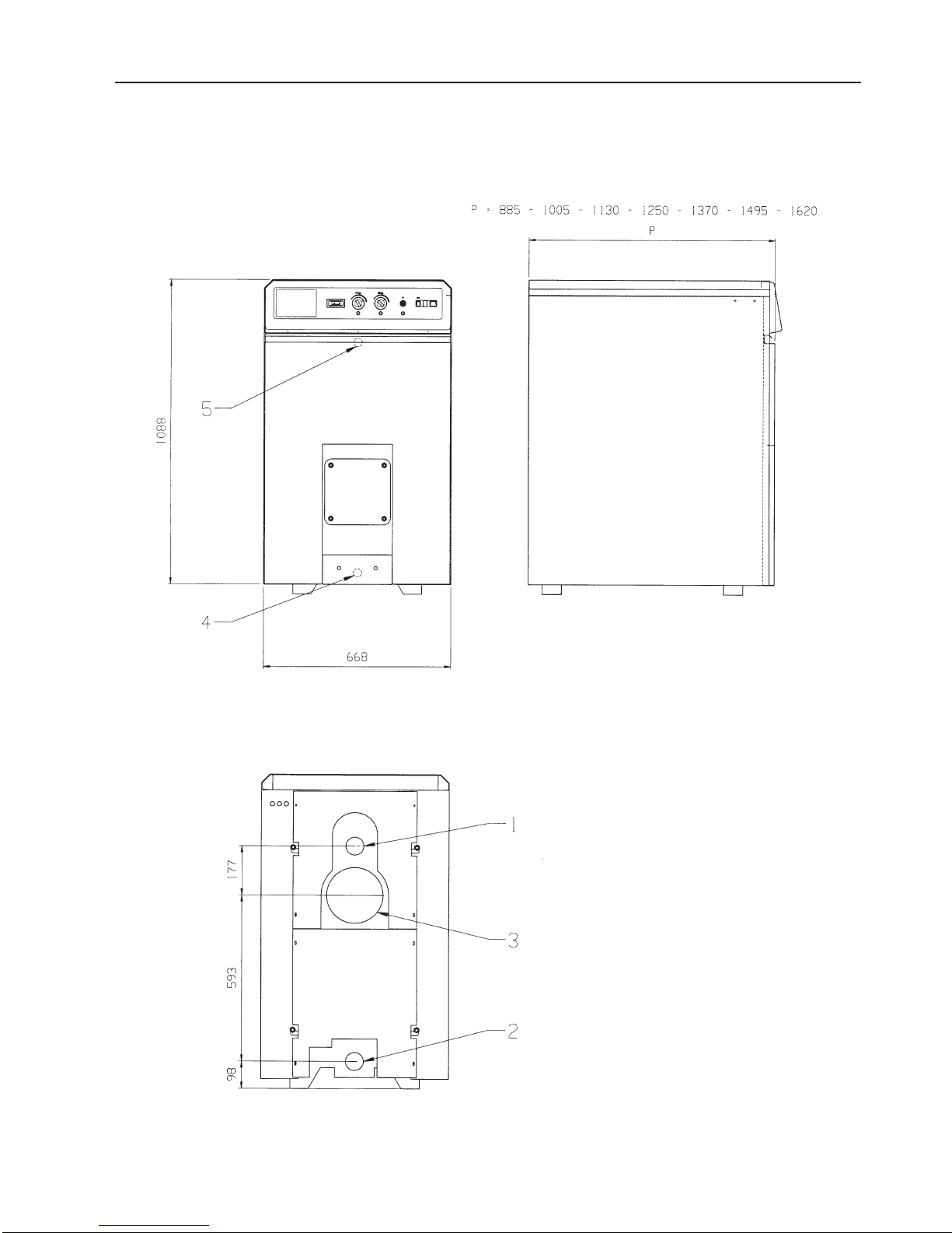
1.3 DIMENSIONS
1. Heating flow
2. Heating return
3. Flue gas connection
4. Drain
5. Sensortube
6
1. TECHNICAL DATA
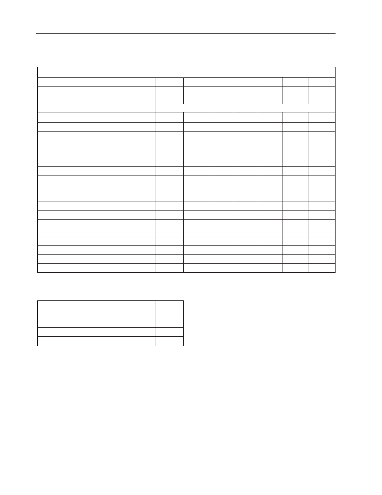
BOILER CTC Maxi80100120140160180200
Number of elements 6 7 8 9 10 1 1 12
Max output power kW 80 10 0 12 0 14 0 16 0 18 0 200
Max input power kW 88,9 1 11,1 133,3 155,6 177,8 200,0 222
Fuel Gas/Fuel-oil
Working efficiency % 90,0 90,0 90,2 90,4 90,4 90,5 90,6
Efficiency at 30% capacity % 88 88 88 88 88 88 88
Loss at the smokestack % 8,4 8,2 8,4 8,4 8,2 8,2 8,2
Smoke temperature* °C 205 20 0 202 202 200 20 0 20 0
Gas smoke flow rate kg/h 13 7 171 206 240 274 309 342
Fuel oil smoke flow rate kg/h 13 1 165 198 231 264 297 33 0
Smoke load losses mbar 0,10 0,15 0,28 0,30 0,40 0,55 0,66
Dimensions of the combustion chamber:
Length mm 565 686 807 928 1049 1 170 1291
Diameter mm 380 380 380 380 380 38 0 380
Volume of the combustion chamber dm
3
72 86 101 116 131 145 159
Smokestack connection mm 200 20 0 200 2 00 20 0 200 200
Water contents l 66,0 76,5 87,0 97,5 108,0 118,5 129,0
Water side load loss Dt = 15°C mbar 9 12 18 28 35 45 60
Delivery connection “G 2 ½” 2 ½” 2 ½” 2 ½” 2 ½” 2 ½” 2 ½”
Return connection “G 2 ½” 2 ½” 2 ½” 2 ½” 2 ½” 2 ½” 2 ½”
Boiler depth P mm 8 85 1005 1 130 1250 1370 1495 1620
Weight of empty boiler kg 41 0 465 520 57 5 63 0 68 5 740
* with CO2% = 13 for Fuel Oil and 10 for Gas
Max. operating pressure ba r 5
T est pressure ba r 7,5
Control thermostats ° C 21-85
Safety thermostat °C 1 10
Code PIN CE 0063/ ...
1.4 TECHNICAL DA T A
 Loading...