

Page 1
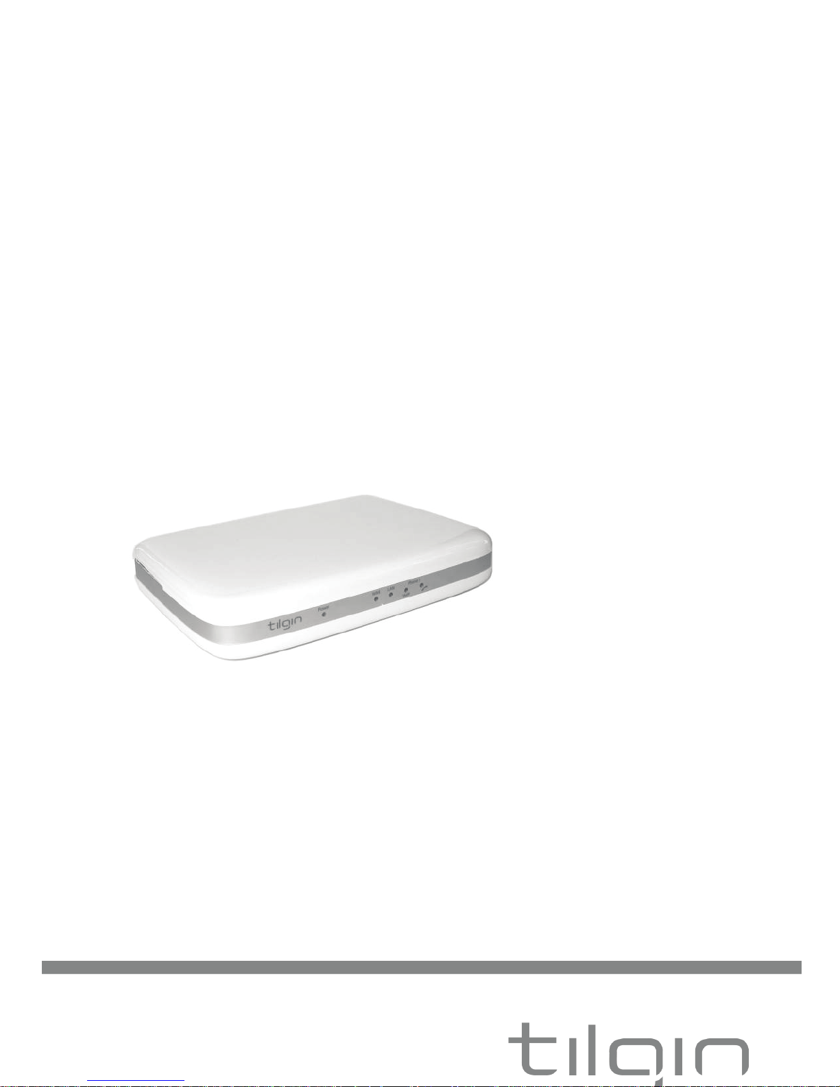
-Tilgin HG320 Series Quick Guide
Tilgin Home Gateway
HG321/HG322
HG320 Series
Quick Guide
Page 2

-Tilgin HG320 Series Quick Guide
Tilgin IPRG AB
Box 1240
164 28, Sweden
tel: +46 (0)8 572 38600
fax: +46 (0)8 572 38500
www.tilgin.com
This product is developed and manufactured by Tilgin IPRG AB.
Document Product Number: 13650015
Content Version: B
Page 3

-Tilgin HG320 Series Quick Guide
Contents
1. Introduction ................................................................................................................. 1
2. Delivered with the Home Gateway Unit .................................................................. 1
3. Home Gateway Overview ......................................................................................... 2
3.1. Home Gateway cable attachments ................................................................. 2
3.2. Home Gateway Interfaces ................................................................................ 3
3.3. LEDs Front Panel .............................................................................................. 4
4. Installing the Home Gateway ................................................................................... 5
4.1. Connecting to the Internet (WAN) ................................................................... 6
4.2. Power on the Home Gateway .......................................................................... 6
4.3. Automatic Provisioning ..................................................................................... 6
4.4. Connecting a computer to your Home Gateway ........................................... 6
4.5. Configuring your computer/device .................................................................. 6
4.6. Connecting phones / equipment...................................................................... 7
5. Troubleshooting Tips ................................................................................................ 8
6. Safety Information ..................................................................................................... 9
7. Safety Recommendations ........................................................................................ 9
8. Power Supply ........................................................................................................... 10
9. Approvals and Conformity ...................................................................................... 10
10. Technical Specifications ......................................................................................... 12
11. Environmental Information ..................................................................................... 12
12. Warranty ................................................................................................................... 12
13. Notice of Copyright and Patent Protection ........................................................... 12
14. How to Wall-Mount the Home Gateway ............................................................... 13
15. Used Acronymes ..................................................................................................... 14
Page 4
1
-Tilgin HG320 Series Quick Guide
1. Introduction
The home gateway you have received enables services provided by your operator
and can become the full service node in your home.
This Quick Guide contains start-up instructions for installing Tilgin Home Gateways
HG320 series. When following the instructions to connect and start-up the home
gateway it will automatically connect to your operators network for enabling services
offered by your operator. If provided, check the instructions from your operator for
additional steps needed when connecting and powering up the device.
2. Delivered with the Home Gateway Unit
Confirm that you have received the following:
Content in packages for HG320 models:
HG320 models: Qty
HG320 series Home Gateway 1
Power Supply 1
Ethernet cable, Yellow 1
Quick Guide (this document) 1
EULA, EndUserLicenseTerms and Conditions 1
Drill Guide for wall mounting the HG32x 1
Your equipment provider might also include additional cables or
country-specific phone plugs.
Page 5
2
-Tilgin HG320 Series Quick Guide
3. Home Gateway Overview
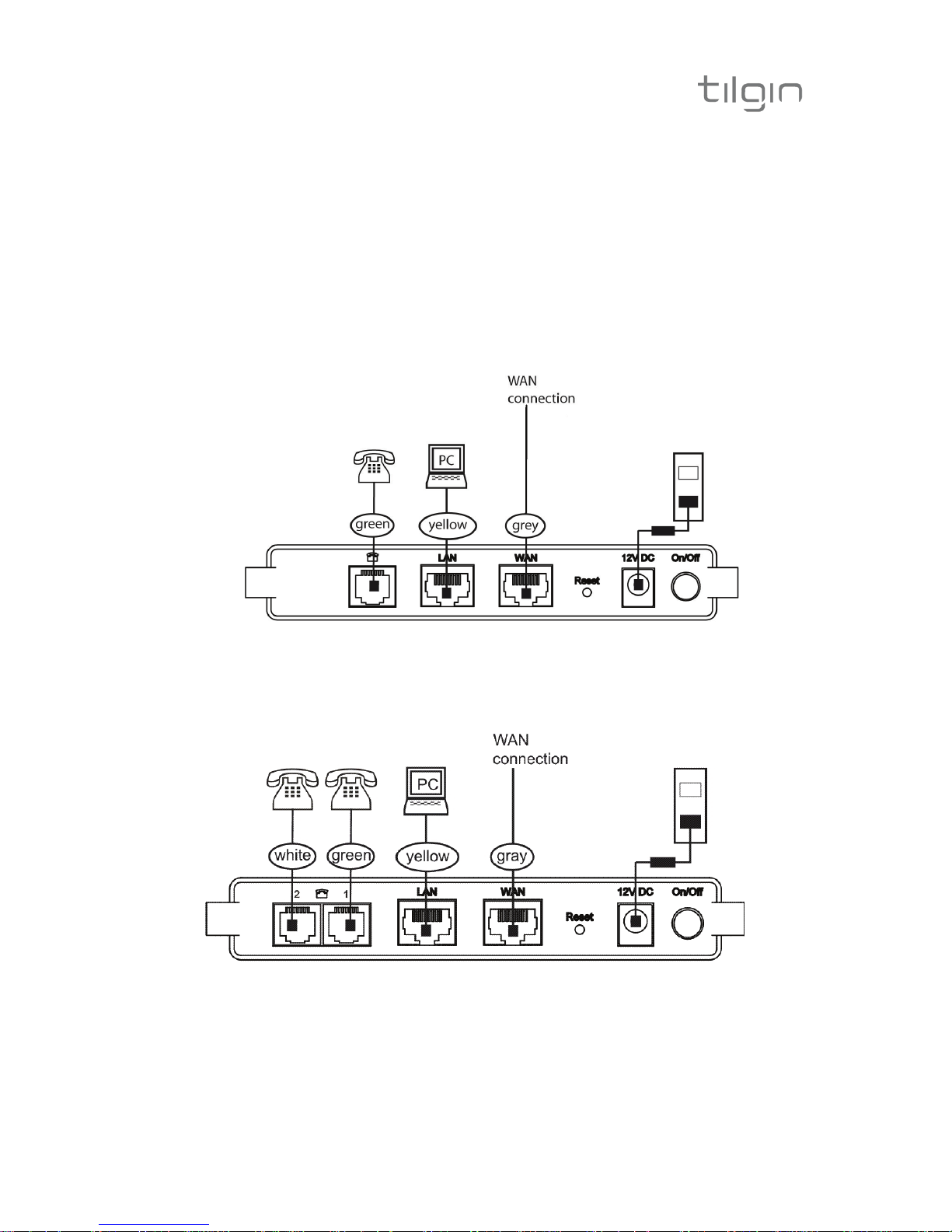
3.1. Home Gateway cable attachments
See more instructions below
HG321 Cable Connections
HG322 Cable Connections
Page 6
3
-Tilgin HG320 Series Quick Guide
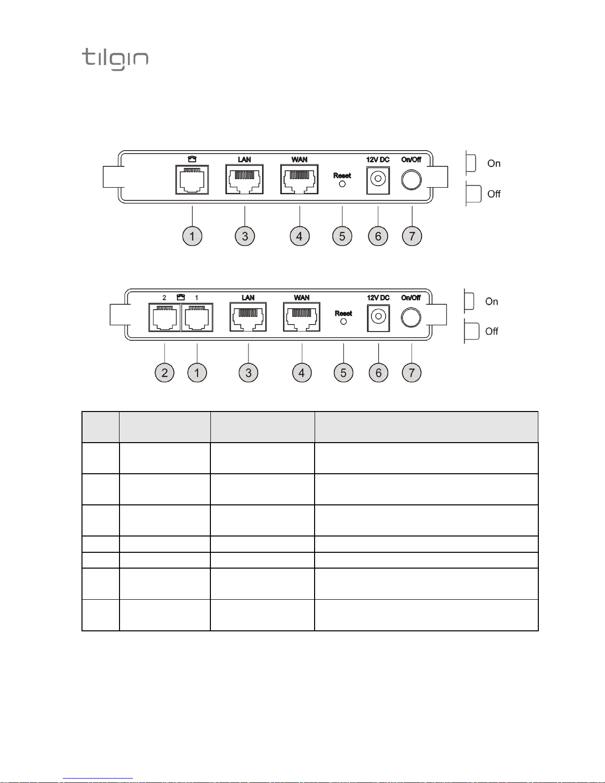
3.2. Home Gateway Interfaces
HG321 Rear Panel
Green Yellow Gray
HG322 Rear Panel
White Green Yellow Gray
Pos Interface Outlet & Cable
Color Codes
Function
1 Phone Port1 Green Connects analogue phones or fax
equipment
2 Phone Port2
(HG322 only)
White Connects analogue phones or fax
equipment
3 LAN Port Yellow Connects to the Local Area
Network
4 WAN Port Gray Connects to WAN (Internet)
5 Reset Button for factory reset
6 Power / DC
Power Input
Black Connects the power adapter
7 On/Off Button for turning the home
gateway on or off
Page 7
4
-Tilgin HG320 Series Quick Guide
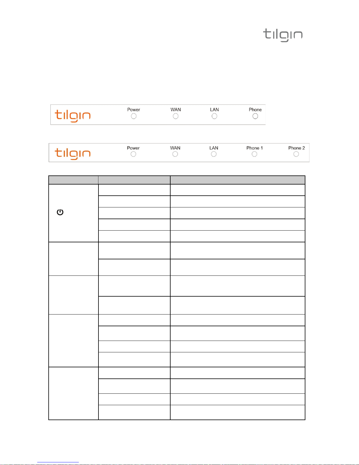
3.3. LEDs Front Panel
Front panel LEDs indicates the status of power and Home Gateway
connections. Ethernet LEDs are located on the rear
HG321 Front Panel
HG322 Front Panel
LED Signaling Indication
power
OFF No power
RED, Stable Not ready, boot in progress
RED, Slow Flash
Connection to operator failed
RED, Rapid Flash Upgrading or connecting
GREEN, Stable Normal operation
WAN
Ethernet
Connector
(Rear, Gray)
GREEN, Rapid Flash Traffic activity
GREEN, Stable Link
LAN
Ethernet
Connectors
(Rear,
Yellow)
GREEN, Rapid Flash
Traffic activity
GREEN, Stable
Link
Phone 1
OFF No telephone services configured
GREEN, Rapid Flash
One or more telephone services failed to
register
GREEN Short Flash Message waiting
GREEN, Stable
The telephone services to your Operator is
OK
Phone 2
(HG322)
OFF No telephone services configured
GREEN, Rapid Flash
One or more telephone services failed to
register
GREEN Short Flash Message waiting
GREEN, Stable
The telephone services to your Operator is
OK
Page 8
5
-Tilgin HG320 Series Quick Guide
4. Installing the Home Gateway
When the home gateway is connected, it will automatically be provisioned by
your operator. However, the level of configuration can vary from a completely
automatic configuration to full manual configuration, depending on what your
operator offers.
Follow the specific configuration instructions you may have received from your
operator.
The home gateway use Web GUI pages for local configuration with your
computer. Pages available in the Web GUI depend on your operator’s offering.
Home gateways and power supplies are electrical devices that can overheat
without ventilation.
Place standing or wall mounted on a firm and flat surface and do not cover or
crowd them with objects or clothing that prevents good ventilation.
Home gateways must always be installed away from heat sources and direct
sunlight.
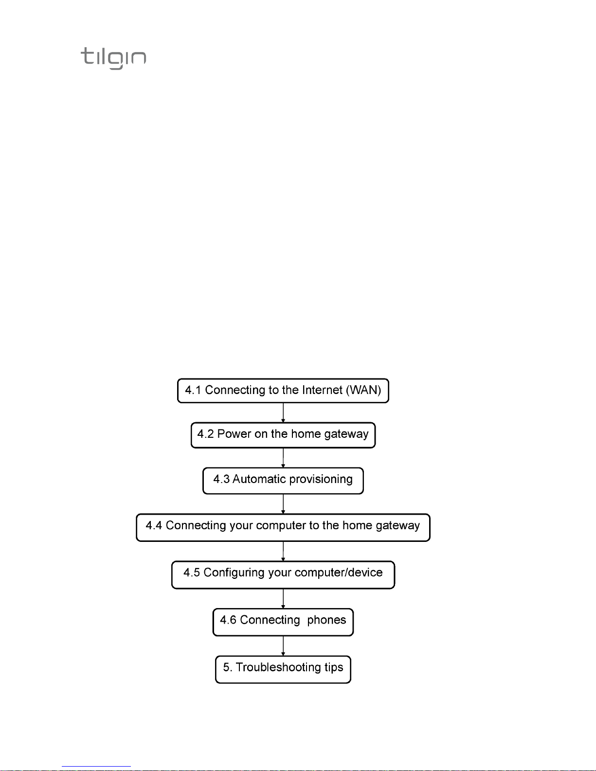
The flowchart below describes the procedures to install your home gateway and
is in detail explained in the following pages
Page 9

6
-Tilgin HG320 Series Quick Guide
4.1. Connecting to the Internet (WAN)
Connect the Ethernet cable into the WAN port ( #4 on the Home Gateway
Interfaces page) and into your Ethernet access port. (Home Gateway cable
attachments)
4.2. Power on the Home Gateway
1. Connect the power cord to the AC/DC adapter
2. Connect the AC/DC adapter power cord to the power connector (#6) on
the backside of the unit.
3. Plug the power cord into a power outlet.
4. Push the ON/OFF-Button (#7) on the backside to ON
5. Check that the power LED on the front panel is lit (red).
4.3. Automatic Provisioning
When the home gateway is properly connected, an automatic configuration will
begin.
The home gateway is pre-loaded with software but it will always download
newer software and settings from your operator.
Just wait until the power LED is stable green, which normally takes a few
minutes, but may take up to 30 minutes. If the LED still does not show stable
green after 30 minutes, then reboot (push power ON/OFF-button). If problem
persists, contact your operator.
For more information about the LED status, see LEDs Front panel.
4.4. Connecting a computer to your Home Gateway
Connect the Ethernet port on your computer with an Ethernet cable to the LAN
port #3.
4.5. Configuring your computer/device
Your computer must be configured properly to be able to connect to the Internet
and the computers network card and network properties must be configured to
obtain an IP address from the home gateway’s built-in DHCP server.
This means that you must check that your computer network settings are set to
TCP/IP protocol and that the IP address will be obtained automatically.
For detailed instructions how to set up your home network check
instructions/Help for your operating system on your computer.
Page 10

7
-Tilgin HG320 Series Quick Guide
4.6. Connecting phones / equipment
You can connect your analogue phones/equipment to the home gateway.
The devices connected to the gateway are adapted for VoIP calls.
Mind that you might need a country specific phone plug and a special phone
cable (both supplied by your operator) to connect multiple analogue devices.
If your services do not include telephony, contact your operator.
Connecting a single analogue phone/equipment
Connect the device(s) to port #1 (and/or #2 (HG322)).
Connecting multiple analogue phones/equipment
All of the phones in your household can be connected to the home gateway
using a country specific phone plug and a special phone cable.
Each port can handle up to five devices in cascade. In this case, DO NOT
connect any of the home gateway phone ports to the phone socket on the wall.
Plug the special cable into the phone port (#1) and then into the specific phone
plug connected on the main phone socket on the wall.
DO NOT use an ordinary phone cable for this purpose. It requires a special
phone cable which can be different from country to country.
This option must be supported in your country and by your operator.
Page 11

8
-Tilgin HG320 Series Quick Guide
5. Troubleshooting Tips
If the home gateway is not working as expected, please try out the following
troubleshooting tips.
• Check the cable connections.
• Check if the power LED is lit. If not push the ON/OFF button to ON.
Check that the power cord is attached in both ends.
• If the power LED not lights stable green within 30 minutes reboot (push
power ON/OFF)
• If the power LED still not lit stable green after reboot contact your
service operator.
• If the WAN indicator (front of the gateway) does not lit green (front of
the home gateway), check that the Ethernet cable is properly
connected.
• Verify that the LEDs lights according to the table in LEDs front panel
page.
• Verify that you can hear a dial tone after hooking off the telephone
receiver. If not check that the telephone line cord from the telephone is
connected to one of the phone ports.
• If your operator provides Web GUI access, status information is
available via a computer login to the home gateway. Please see
information provided by your operator.
If these actions still do not solve the problem, contact your operator or the
vendor that supplied your home gateway.
Page 12

9
-Tilgin HG320 Series Quick Guide
6. Safety Information
Tilgin IPRG AB products are designed and tested to meet the international Safety of
Information Technology Equipment standard. This standard provides general safety
design requirements that reduce the risk of both personal injury and product injury,
protecting against the following hazards:
• Electric shock (hazardous voltage levels)
• Fire (overload, temperature, material flammability)
• Energy (high energy circuits or potential burn hazards)
• Heat (accessible parts of the product at high temperatures)
• Radiation (noise, etc.)
7. Safety Recommendations
When using the product and to ensure general safety, you are instructed to
follow these guidelines:
• Use only the power supply adapter that comes with the package.
Replacement power supply adapters can be obtained from an
authorized Tilgin distributor.
• Do not open or disassemble this product.
• Place on a firm and flat surface.
• Home Gateways and power supplies are electrical devices that can
overheat without ventilation. Do not cover or crowd them with
objects or clothing that prevents good ventilation.
• Do not expose the product to liquid or moisture.
• Do not expose the product to lit candles, cigarettes, open flames,
etc.
• Do not drop, throw or try to bend the product.
• Do not allow children to play with the product, as it contains small
parts that could be detached and create a choking hazard.
• Use only original Tilgin components and replacements parts.
Failure to do so may result in performance loss, damage to the
product, fire, electric shock or injury. It will also invalidate the
warranty.
• Avoid using the unit during an electrical storm. There may be a
remote risk of electric shock from lightning.
• Treat the product with care, keep it in a clean and dust free place.
Use only a soft, damp cloth to clean the product.
All use of the product is subject to the Safety Recommendations above.
Tilgin IPRG AB waives all and any liability for damages caused to i) the
product or any other property or ii) yourself or any other individual as a
consequence of using the product in ways that deviate from the safety
recommendations set out above.
Page 13
10
-Tilgin HG320 Series Quick Guide
8. Power Supply
Do not use any other power supply than the one delivered by Tilgin.
Using the wrong power supply could be hazardous to you or the product.
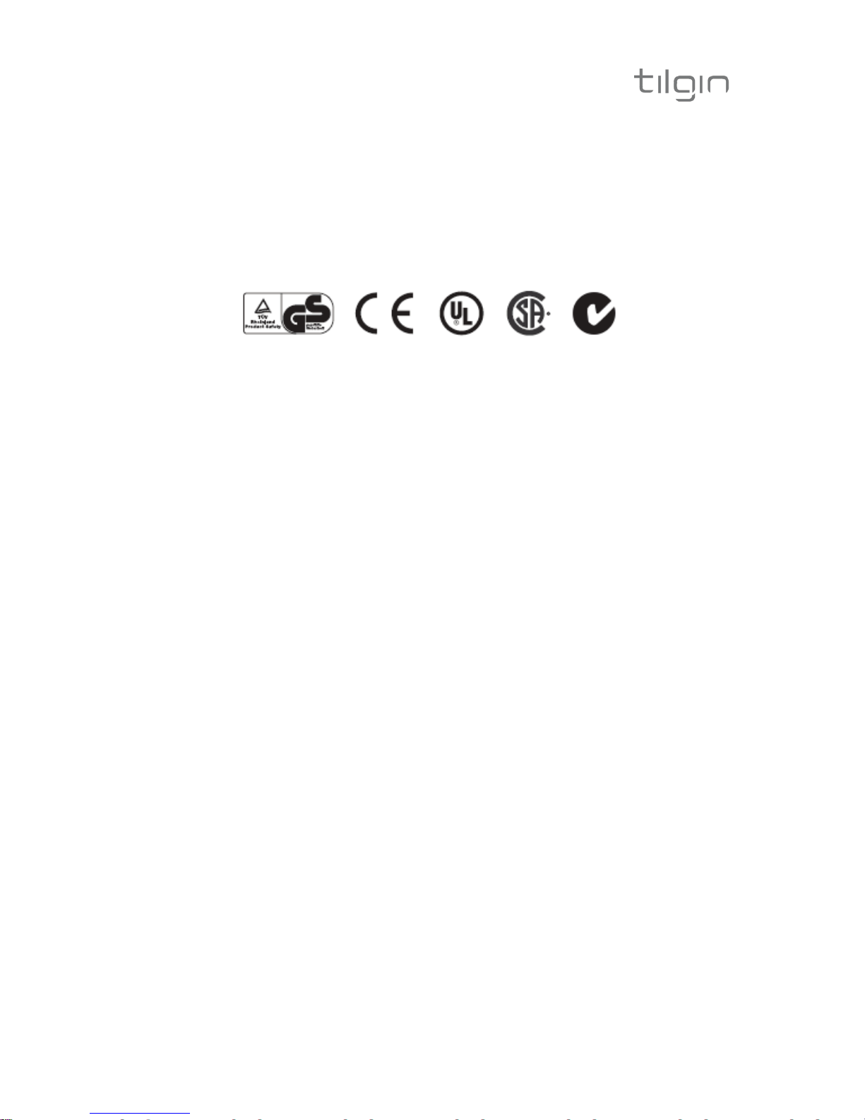
The power supply is approved by one or more of the following safety organizations:
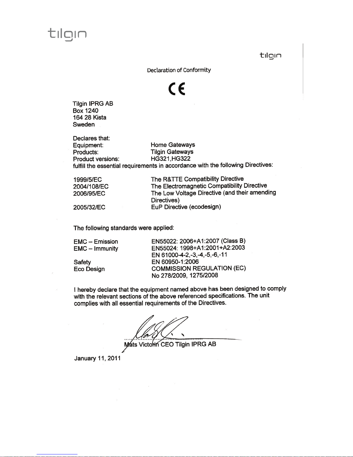
9. Approvals and Conformity
Tilgin’s HG320 Series Home Gateways are also subject to FCC approval.
Page 14
11
-Tilgin HG320 Series Quick Guide
Page 15
12
-Tilgin HG320 Series Quick Guide
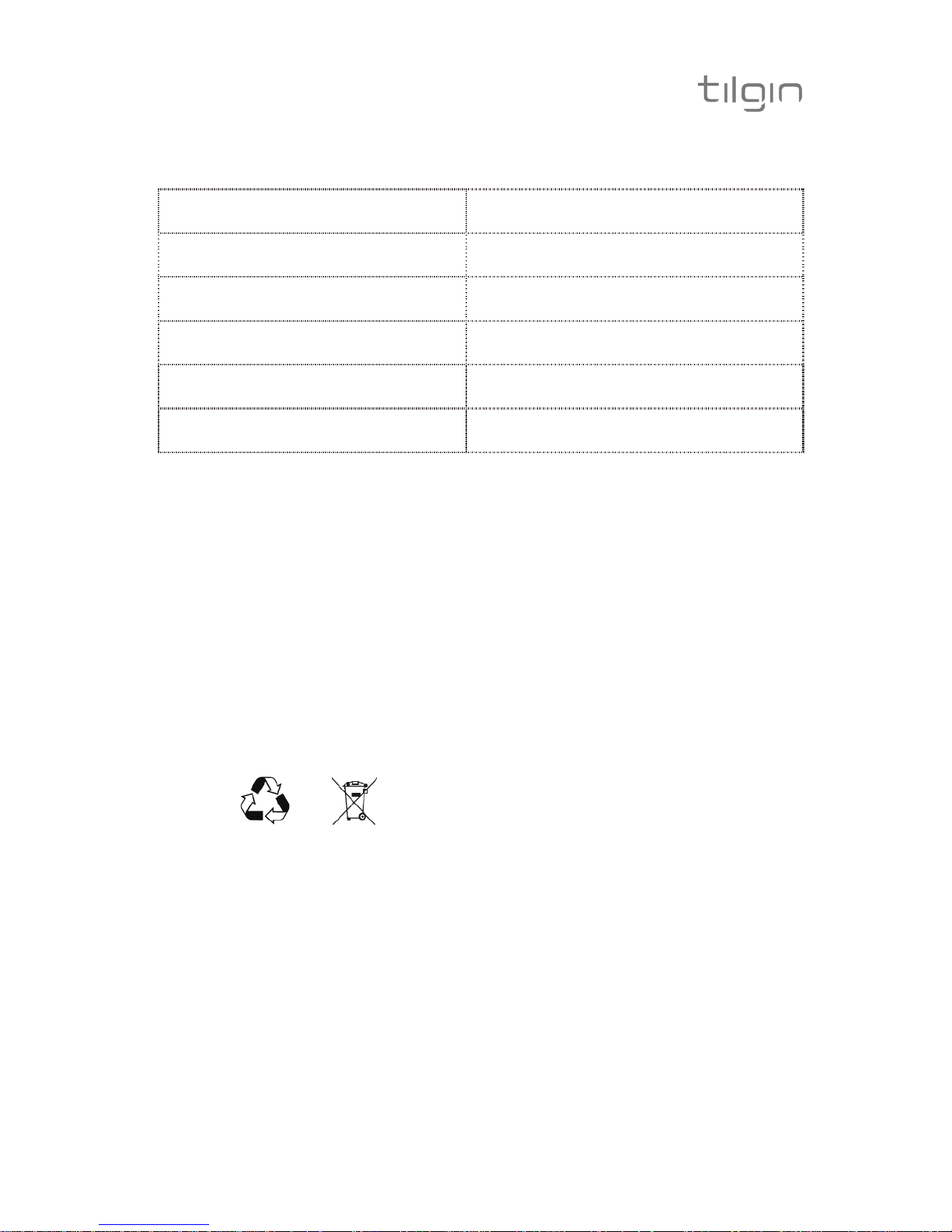
10. Technical Specifications
Dimensions 171 x 111 x 33 mm
Weight 0.25 Kilograms
Operating voltage
See the supplied power
adapter
Operating frequency
See the supplied power
adapter
Temperature
Operating: 0° C to 40° C
Non-operating: -20° C to 60° C
Humidity (relative, noncondensing)
Operating: 10% to 90%,
Non-operating: 5% to 95%
11. Environmental Information
The equipment you purchased has required the extraction and use of natural
resources for its production. It may contain substances that are hazardous to your
health and to the environment. To avoid putting such substances into our
environment and to reduce pressure on our natural resources, we ask that you
reuse or recycle your end-life equipment by using an accredited electronics takeback system.
The symbols below indicate that this product should be reused or recycled and not
simply discarded. Please locate and use an appropriate reuse and recycling site. If
you need more information on collection, reuse and recycling systems, contact your
local or regional waste administration. You may also contact your operator for more
information on the environmental performances of these products.
12. Warranty
No warranty, express or implied, with respect to the product is extended
directly to you from or on behalf of Tilgin IPRG AB. Limited warranties may
be granted to you by the equipment provider in its capacity as reseller of the
product. Please contact your equipment provider for information regarding
warranties for the product.
13. Notice of Copyright and Patent Protection
This product incorporates technology which is copyrighted or patented or
otherwise protected under intellectual property laws and treaties and
proprietary to Tilgin IPRG AB or Tilgin’s third party licensors. All use of the
products is subject to the applicable End User License Terms and
Conditions provided in conjunction with the product.
Page 16
13
-Tilgin HG320 Series Quick Guide
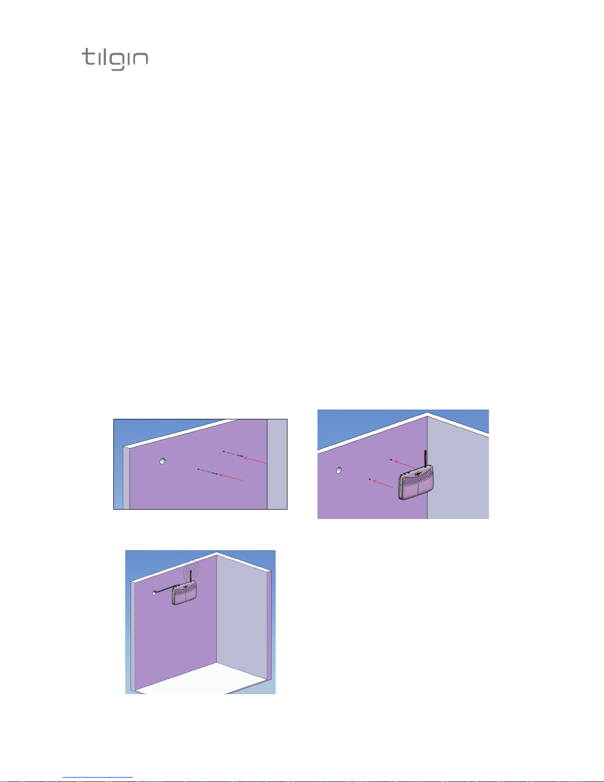
14. How to Wall-Mount the Home Gateway
Wallmounting Instruction
The device can be mounted on the wall.
To install:
1. Screw appropriate screws to the wall where the device is to be placed.
See 13650037 Drill Guide for wall mounting the HG32x
appended in the gift box for drilling correctly spaced holes.
The template shows an outline view of the product with two indicated drill
locations.
When you have marked the drill locations on your wall, drill two holes and insert
two suitable screws.
2. Let the bottom of the device face the wall and mount the device on the screws.
3. Connect the cables to the rear panel.
Figure: Mounting the device to the wall:
12
3
TI-DEV_IPRG_09_054 Ver A
Page 17

14
-Tilgin HG320 Series Quick Guide
15. Used Acronymes
LAN Local Area Network
LED Light Emitting Diod
VoIP Voice over IP
WAN Wide Area Network
Page 18

-Tilgin HG320 Series Quick Guide
Empty Page
Empty Page
Page 19

-Tilgin HG320 Series Quick Guide
Empty Page
Page 20

-Tilgin HG320 Series Quick Guide
This product is developed and manufactured by Tilgin IPRG AB
Copyright © 2011 Tilgin IPRG AB
All rights reserved. This Quick Guide and any associated artwork, software, and product designs are copyrighted with
all rights reserved. Under the copyright laws this Quick Guide, artwork, software, and product designs may not be
copied, in whole or part, without the written consent of Tilgin IPRG AB. Under the law, copying includes translation to
another language or format.
Any Open Source code contained in this product is available as a free download from http://www.tilgin.com
 Loading...