

TileWare Victoria Series, T200-001 Series, T200-002 Series, T200-001-PC, T200-001-BN Installation Procedures Manual
...
Fastener
Thumb screw
Stud
Stabilizer
MORTAR BASED INSTALLATION SYSTEM – NO MASTIC
Victoria™ Series ADA 18” Grab Bars
Installation Procedures For The Following Models:
Model T200-001
ADA 18” Straight Grab (Contemporary)
Note: System will not work on tile thicknesses less than
5/32” or greater than 1/2”
Revised: 1/29/16
Model T200-002
ADA 18” Straight Grab (Traditional)
T200-001-PC T200-001-BN T200-001-ORB
T200-002-PC T200-002-BN T200-002-ORB
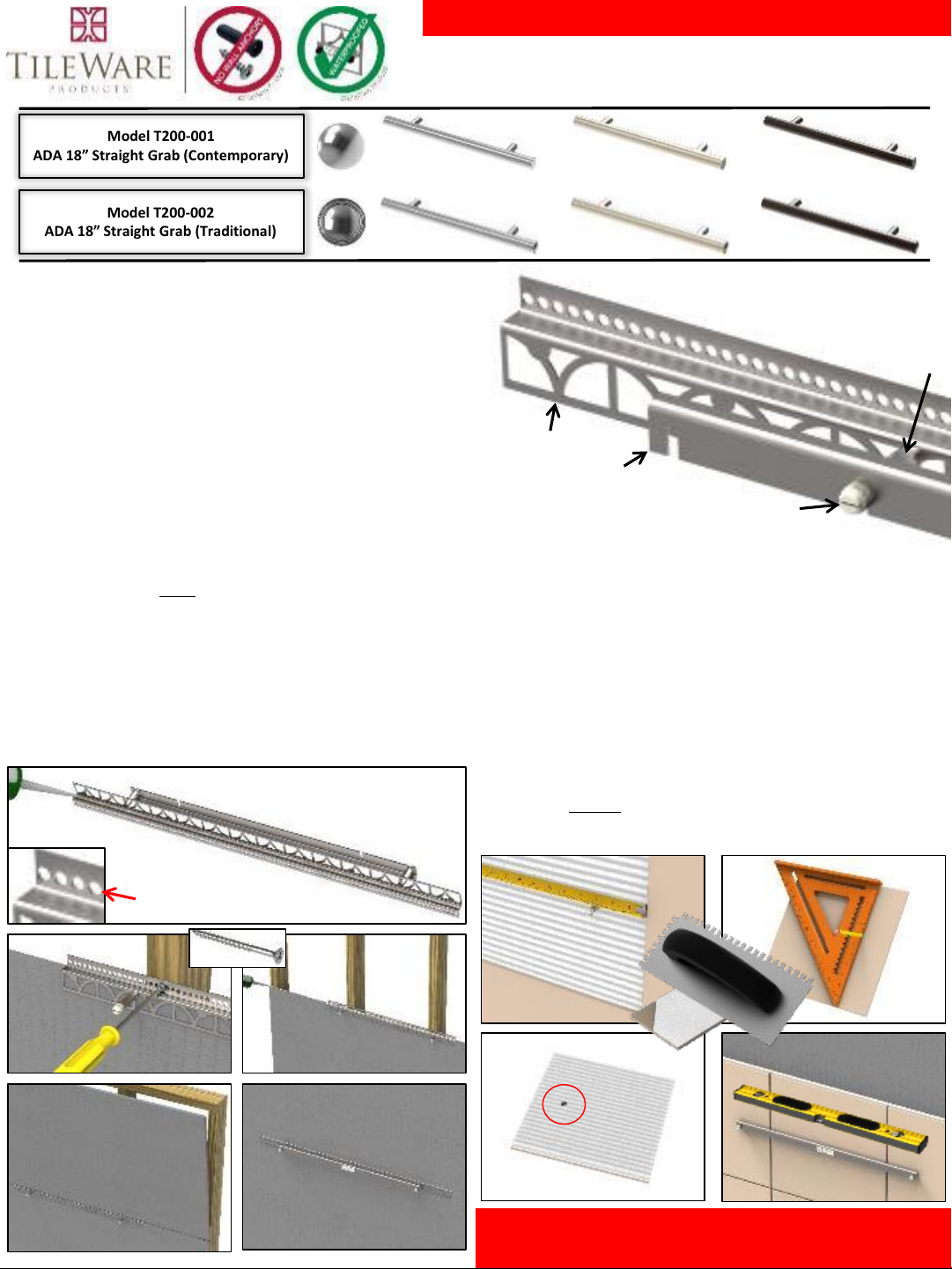
STEP 1 Understand “Z” Fastener
• Each PermaTile™ Fastener is equipped with a stabilizing bracket. The bracket
ensures that grab bar mounts properly. Remove stabilizer after thin-set has
met minimum cure times specified by manufacturer.
Warning: Each threaded stud is covered with a plastic thumb screw to prevent
thin-set mortar from corrupting threads. Do not remove until after grouting.
Technical Fact:
Each PermaTile™ “Z” Fastener is constructed from high quality stainless
steel materials. The welded fastener is equipped with (2) 10-24 internal
threaded studs (only one pictured)
STEP 2 Determine Location & Install Fastener
Technical Fact:
Each PermaTile™ “Z” Fastener will work with all 1/2” thick cement, fiber
and foam-core tile board materials. (Only use materials that meet ANSI
specification for tile construction.)
Determine where the PermTile™ “Z” Fastener will be located.
• First apply a 1/4” bead of urethane caulk to underside of “Z” Fastener to
waterproof.
• Attach “Z” Fastener to wood studs with #8 x 2” wood screws (2-
provided). Fastener MUST be mounted to 2 stud placements 16” on
center.
• After attaching fastener, apply a second bead of urethane caulk on top
of tile board edge, covering entire edge including fastener.
• Place tile construction board on top of fastener system and attach
securely.
Warning: When installing “Z” Fastener for
ADA, first consult local municipalities.
• Apply thin-set mortar with no less than a 1/4” x 3/8” notch trowel, key
thin-set into perforations in “Z” Fastener.
• Measure location of threaded stud by marking tile or using a tape
measure.
• Transfer marks using a square.
• Use only 10mm diamond drill bit (core), pre-drill all holes before applying
thin-set mortar. Back-butter tile making sure sufficient mortar is around
drilled hole.
Warning: Use only latex modified mortars that meet ANSI A118.4 or A118.11
performance standard. Notches or drilled holes should not exceed 3/8” in
diameter to ensure trim has sufficient surface area during grab bar mounting.
Inadequate mortar coverage around drilled or notched holes will result in tile
damages when tightening bushing and mounting grab bar.
STEP 3 Install Tile over “Z” Fastener
Technical Fact:
When drilling glass tile always drill from both sides. Failure to do so will create
blow-outs and weaken tile structure. Do not mount grab bar to glass tile
where drilling has occurred on one side only.
Note: Mortar required around hole
Thin-Set
Use wood
screw provided
Attach #8 x 2” wood screw
using small perforations
Use level to ensure all
tiles in fastener are FLAT
& on identical plane
Grab Bar Screw
Configuration
Guidelines
5/32” 3/16” 1/4” 5/16” 3/8” 7/16” 1/2”
Thin-Set
& Screed
Build-up
Thicknesses
1/16”
3/16”
3/8” N/A
©2012-2016 TileWare Products. All rights reserved. PermaTile™ Fastener Patented. US Patent No. 8,161,700, Australian Patent No. 2011205360
MORTAR BASED INSTALLATION SYSTEM – NO MASTIC
Victoria™ Series ADA 18” Grab Bars
Installation Procedures For T200-001 & T200-002
Thank you for using our
products!
TileWare Products
PO Box 793, Hickory, NC 28603
Technical Support: 828-322-9273
Email: info@tilewareproducts.com
www.tilewareproducts.com
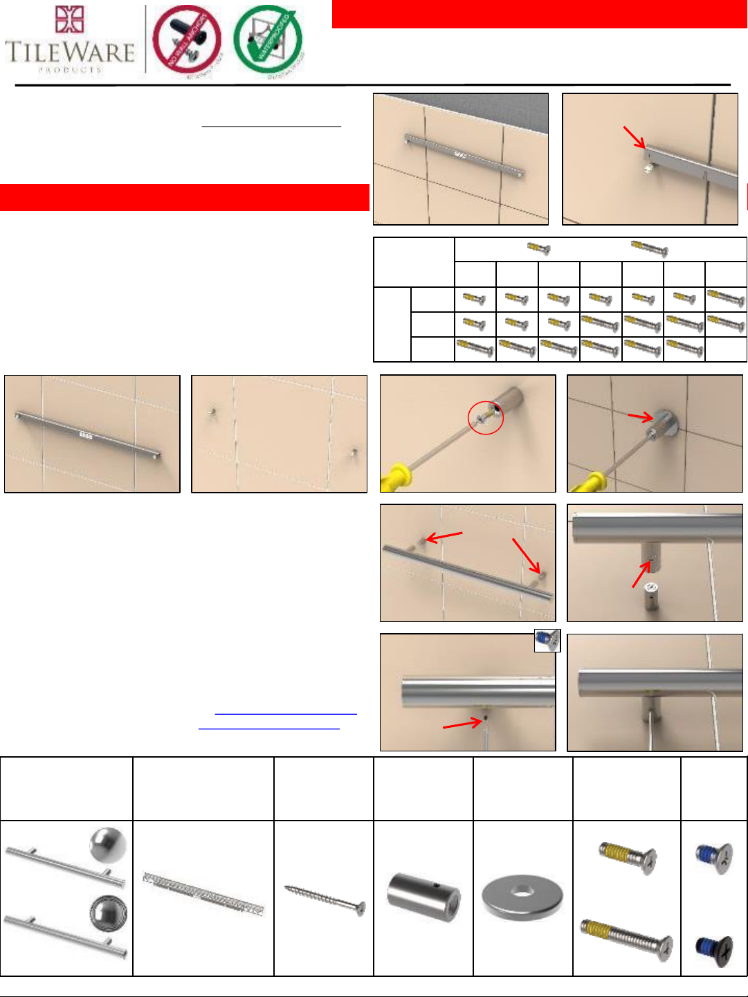
STEP 4 Remount Stabilizer
Warning: Do not proceed with accessory installation until thin-set mortar has
met minimum curing requirements specified by manufacturer.
Remount stabilizing bracket as shown and tighten thumb screws securely. Use
stabilizer to check if “Z” Fastener was installed level.
• Immediately proceed to accessory mounting after grouting is completed.
• Simply slip Bushing over hex studs. Position 6-32 threads down by placing
index finger over threaded hole while slipping onto hex stud.
• Attach to hex studs using 10-24 stainless steel screws (see table to right).
Hand tighten with #2 Phillips head screw driver.
Technical Fact:
Mortar coverage behind drilled hole will ensure bushing can be firmly
mounted with 10-24 stainless steel screw. Screw is patched to prevent threads
from reversing or loosing.
STEP 5 Remove Stabilizer & Install Bushings
• Each Grab Bar is drilled with 2 countersink holes that will match mounted
bushing locations. Simply slip grab bar over bushings (Note: tolerances are
precise so grab bar will feel snug when installing).
• Simply insert 6-32 stainless steel screws through countersink holes in grab
bar and attach to threaded bushings.
• Using a #2 Phillips-head screw driver, attach screws firmly to grab bar.
Loosely mount all screws first before firmly tightening.
Warning: Make sure screw and stud are parallel to avoid cross-threading. Turn
carefully, cross-threading will require fastener removal.
STEP 6 Mount Grab Bar
Grab Bar
quantity 1 per kit
PermaTile™ “Z” Fastener
quantity 1 per kit
Wood Screw
quantity 2 per kit
Bushing
quantity 2 per kit
Optional
Cover Washer
quantity 2 per kit
10-24
3/4” - 1 1/4” Screw
quantity 2 each per
kit
6-32
Screw
quantity 2
per kit
A220-181
A220-182
PT100-514 C200-026 C220-021 C220-023
SOLD
SEPERATELY
C200-015
&
C200-027
C200-011
OR
C200-012
Grab Bar Parts List
Not using stabilizer will result in grab bar mounting failure
Use 6-32
Screws provided
Use 10-24
screws provided
Optional
Cover Washer
to correct
drilling/notch
errors
Stabilizer used as leveling
tool & drilling template
Screws For Specific
Tile Thicknesses:
10-24 x 3/4” Screw
For Standard Build-up
10-24 x 1 1/4” Screw
For Thicker Screeds
Countersink
hole
Bushings
 Loading...