

Page 1
TILEVISION
the bathroom television
®
HIGH-DEFINITION MULTIMEDIA INTERFACE
TM
WATERPROOF
IP65
Digital Television
Analogue
Television
HD
Satellite
Television
22
26
Page 2
HIGH-DEFINITION MULTIMEDIA INTERFACE
TM
WATERPROOF
IP65
Waste Electrical and Electronic Equipment (WEEE) Directive
In the European Union, this symbol indicates that this product should
not be disposed of with household waste. It should be deposited at an
appropriate facility to enable recovery and recycling.
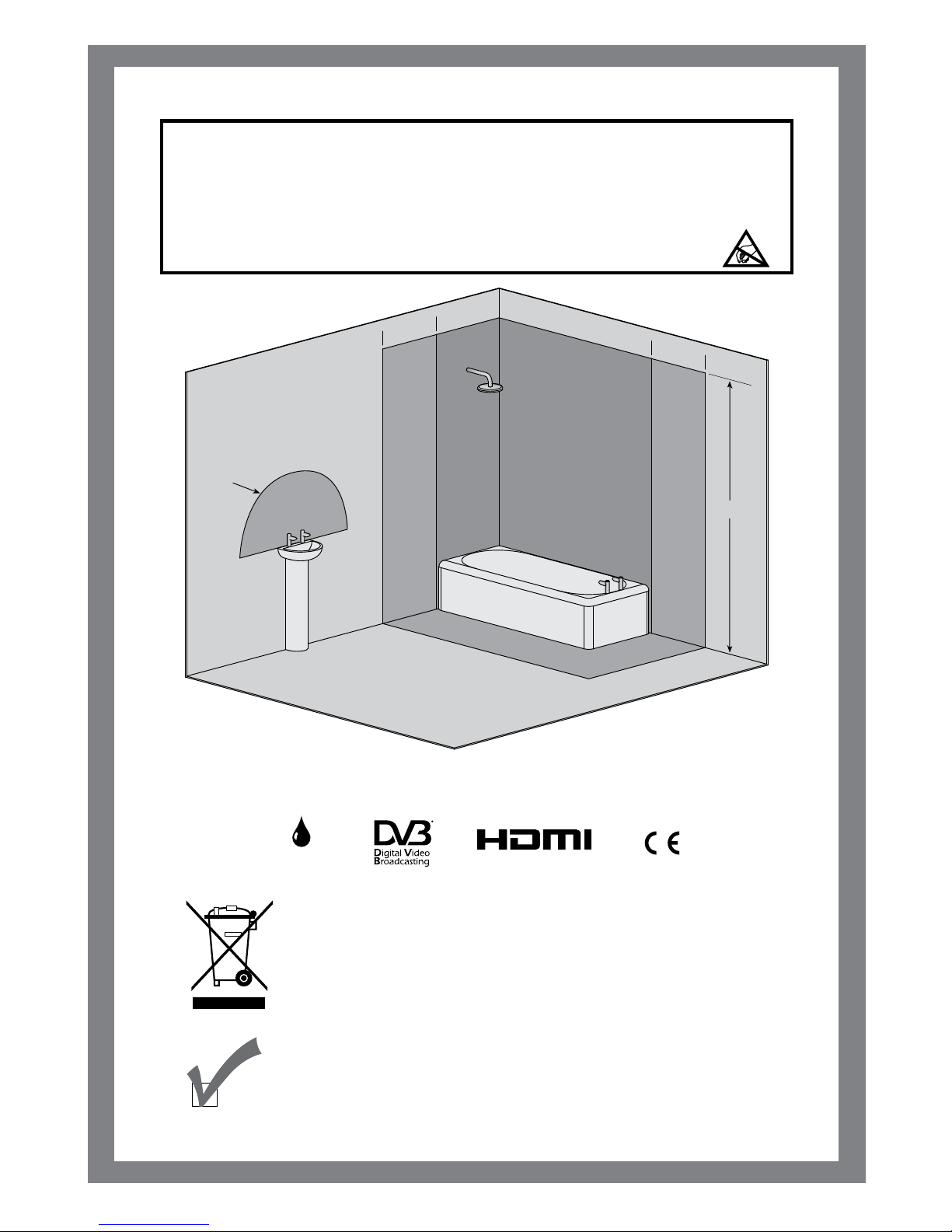
This equipment has an IP65 rating and is suitable for use in Zone 1 and Outside Zones.
Zone 1
Zone 2
600mm
2250mm
Zone 1
Zone 2
Zone 2
Radius
600mm
600mm
Zone 2
Zone 0
Zone 0
Zone 0
IEE Bathroom Zones
CAUTION: RISK OF ELECTRIC SHOCK DO NOT OPEN
WARNING: TO PREVENT INJURY, THIS APPARATUS MUST BE SECURELY ATTACHED TO THE WALL IN
ACCORDANCE WITH THE INSTALLATION INSTRUCTIONS.
CAUTION: DO NOT REMOVE COVER. NO USER-SERVICEABLE PARTS INSIDE. REFER SERVICING
TO QUALIFIED SERVICE PERSONNEL. BEWARE OF STATIC SENSITIVE PARTS.
This product contains Electrical/Electronic Parts which are produced
usingcomponents in compliance with the requirements of: European Union
Directive
2002/195/EC
for the Restriction of the use of certain
Hazardous
Substances in Electrical and Electronics Equipment (RoHS).
RoHS
COMPLIANT
Page 3
1
Safety Instructions and Warnings
To prevent injury, the TileVision® must be securely attached to the wall in accordance with the installation
instructions.
The power supply must be connected to a mains socket outlet with a protective earth connection.
The mains isolation switch must remain readily operable.
Failure to observe the above safety warnings may invalidate the warranty.
All electrical installation should be carried out by a fully qualified electrician.
Do not attempt to service the unit.
Contact an authorised dealer or repair service.
Do not add an additional screen or cover the TileVision’s glass
The heated screen prevents condensation forming in steamy
rooms and covering the screen may cause the unit to overheat.
TileVision Model TV/________________ Serial Number______________ Date of Purchase____/____/20____
Purchased from ______________________________________________________________________
______________________________________________________________________
______________________________________________________________________
______________________________________________________________________
Record important information
Check the contents of each box is correct
Contents first fix kit page 4
Contents second fix kit page 5
If any items are missing, contact the dealer that supplied the TileVision®.
Page 4
2
Silicone Sealant produces acetic acid during cure. Use
only in well ventilated areas. Irritating to eyes. Wash
hands after use and before meals. Wash splashes
from skin, clothing and other surfaces. Use a clean
cloth. In case of contact with eyes wash immediately
with plenty of water.
Please observe safety precautions on the container.
Keep out of reach of children and animals.
Isopropyl alcohol is available from most pharmacies
and larger electronics wholesalers. It is an effective
degreasing agent.
Please observe safety precautions on the container.
Keep out of reach of children and animals.
Do not drink.
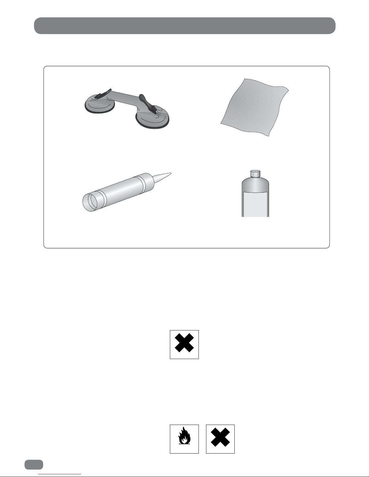
Tools Required
Suction Lifter
Clear Silicone Sealant
Isopropyl Alcohol
I
s
o
p
r
o
p
y
l
A
l
c
o
h
o
l
Soft Cloth
HIGHLY
FLAMMABLE IRRITANT
IRRITANT
Page 5

3
Table of Contents
Safety Instructions and Warnings ..................................................................................................... 1
Tools Required
.......................................................................................................................................... 2
Contents - First Fix Kit
........................................................................................................................... 4
Contents - Second Fix Kit
.................................................................................................................... 5
First fix kit - Initial Assembly
............................................................................................................... 6
Recess Dimensions
............................................................................................................................ 7
First Fix Kit - Installing The Back Box
................................................................................................ 7
First Fix Cabling
....................................................................................................................................... 8
The Splashproof Remote Control - Fitting The Battery
............................................................10
Checking The Back Box
.......................................................................................................................11
The Common Interface (CI) Port
.....................................................................................................11
Sky™ Remote Control Link Setup
...................................................................................................12
Installing the TileVision
®
– Initial Connections ........................................................................... 13
TileVision
®
Connectors ........................................................................................................................14
The IR Link, RJ12 and RS-232 Connectors
................................................................................... 18
Installing the TileVision
®
– Setup and Tuning .............................................................................19
Installing the TileVision
®
– Sealing .................................................................................................20
The Splashproof Remote Control
....................................................................................................21
The Standard Remote Control
..........................................................................................................22
Switching the TileVision
®
On/Off .....................................................................................................23
Selecting the On-screen Language
................................................................................................23
Selecting a Source
................................................................................................................................24
Auto Tuning
.............................................................................................................................................25
Manual Tuning
........................................................................................................................................29
Programme Edit
.....................................................................................................................................32
Signal Information / CI Information
................................................................................................34
Changing Channels
..............................................................................................................................35
Programme Information
.....................................................................................................................36
The Electronic Programme Guide (EPG)
....................................................................................... 37
EPG Timer Recording and Programme Reminders
....................................................................38
The Personal Video Recorder (PVR) / Digital Media Player
...................................................42
Picture Settings
.....................................................................................................................................43
Subtitles
....................................................................................................................................................46
Sound Settings
......................................................................................................................................46
Time Functions
......................................................................................................................................50
Language Selection
.............................................................................................................................54
PVR File System
....................................................................................................................................56
ECO Mode
................................................................................................................................................56
Restore Default
.....................................................................................................................................57
On Screen Display (OSD) Time
.........................................................................................................57
Lock System / Parental Control
.........................................................................................................58
DTV Text
...................................................................................................................................................60
ATV Teletext
............................................................................................................................................61
Remote Control - How to Control a Device
..................................................................................62
Remote Control - Entering a Brand Code
....................................................................................62
Remote Control - Programming a Button
..................................................................................... 65
Remote Control - Troubleshooting
..................................................................................................66
TileVision - Troubleshooting
..............................................................................................................67
Specifications
.........................................................................................................................................68
Page 6
4
1
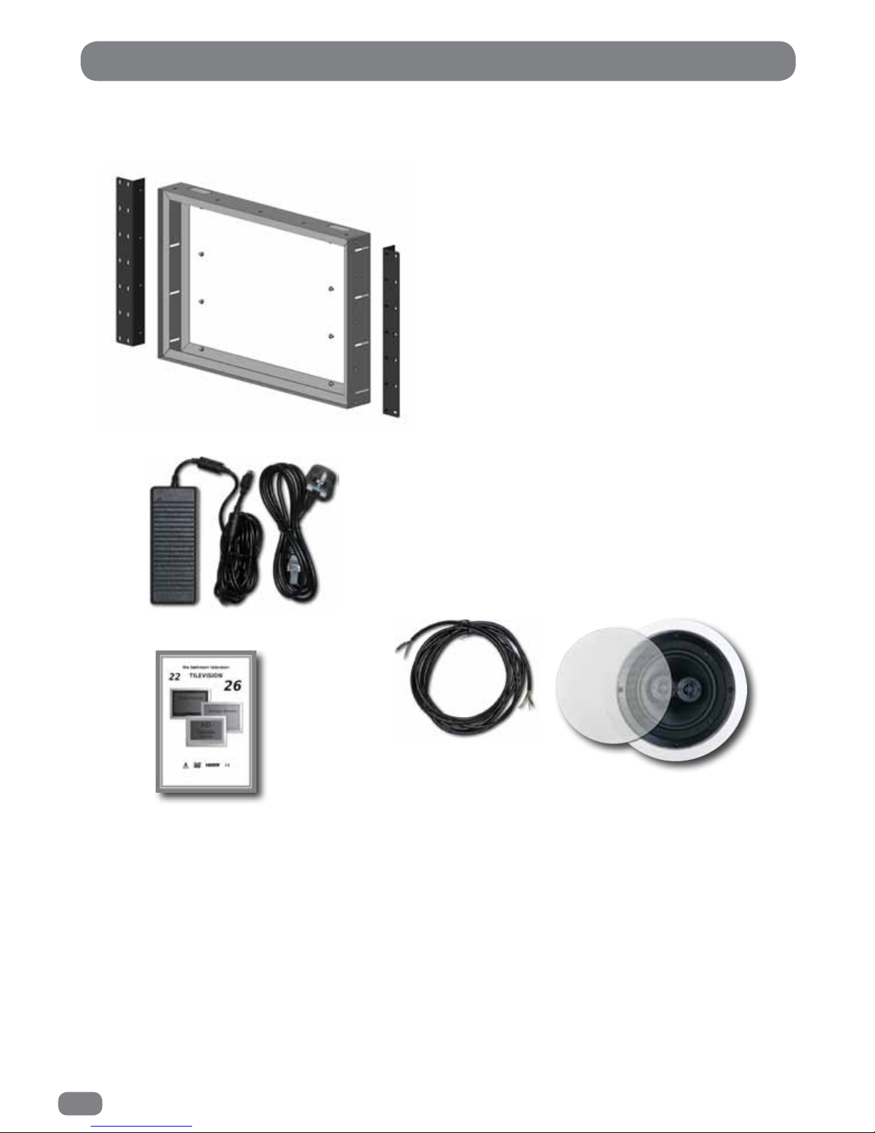
Contents - First Fix Kit
AC to DC power supply with 4
metres of cable and a mains lead
complete with a UK3-pin plug.
Comprehensive
installation and
operating
instructions
Stainless steel back box with
mounting brackets and captive
earthing straps.
Ten machine screws to fasten the
mounting brackets to the back
box are also included.
Note: only eight machine screws
are required for the 22"
TileVision®.
One ceiling/wall mount water resistant stereo
speaker with speaker grille and 4.5metres of
4-core colour coded cable.
If any items are
missing, contact the
dealer that supplied
the TileVision®.
2
4
3
Page 7
5
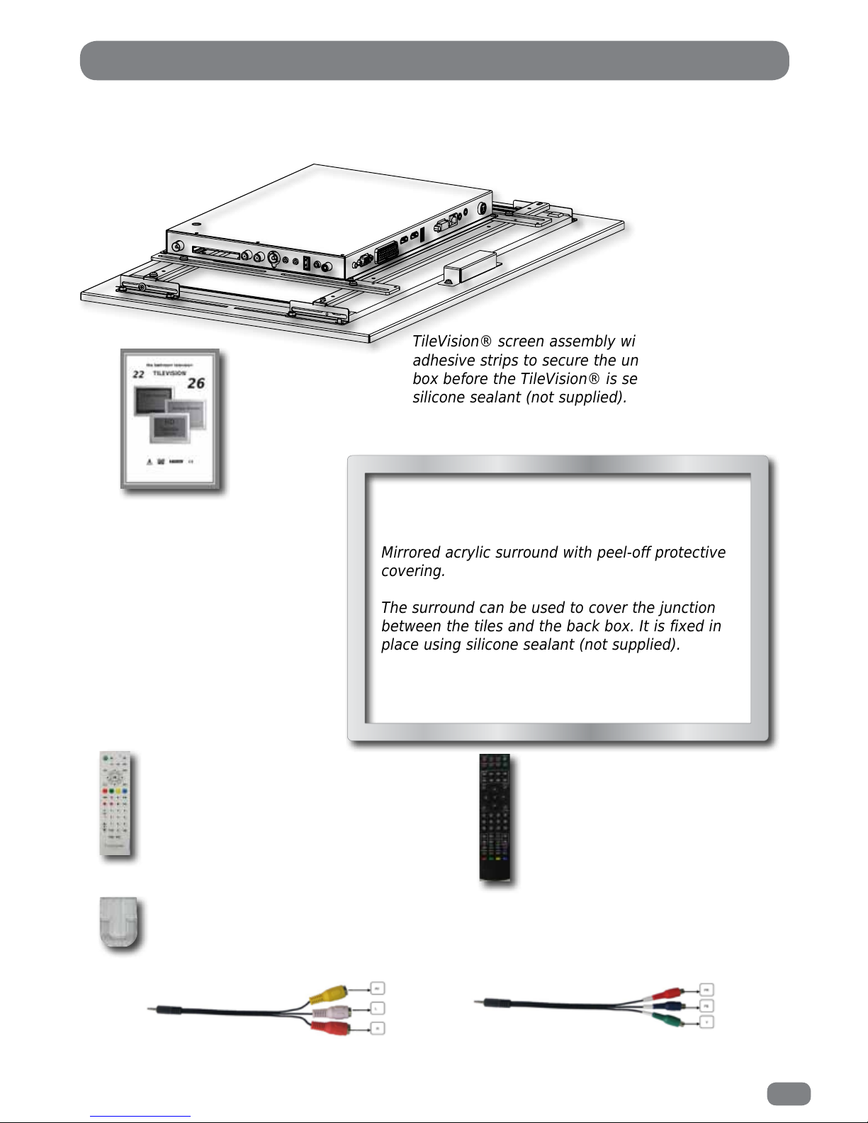
Contents - Second Fix Kit
TileVision® screen assembly with four Velcro self-
adhesive strips to secure the unit into the back
box before the TileVision® is sealed in place with
silicone sealant (not supplied).
Mirrored acrylic surround with peel-off protective
covering.
The surround can be used to cover the junction
between the tiles and the back box. It is fixed in
place using silicone sealant (notsupplied).
Splashproof universal learning remote
control with 3 Vlithium cell ready
installed. An insulating disc must be
removed to activate the remote
control.
Transparent self-adhesive
remote control holder.
Standard full-function remote
control with AAAbatteries
(not waterproof).
Comprehensive
installation and
operating
instructions
Composite cable
Component cable
If any items are
missing, contact the
dealer that supplied
the TileVision®.
1
2
3
5
6
7
8
4
Page 8
6
Please note – A technically competent person should carry out the
installation of your TileVision® unit.
First Fix Kit – Initial Assembly
Unpacking your TileVision
®
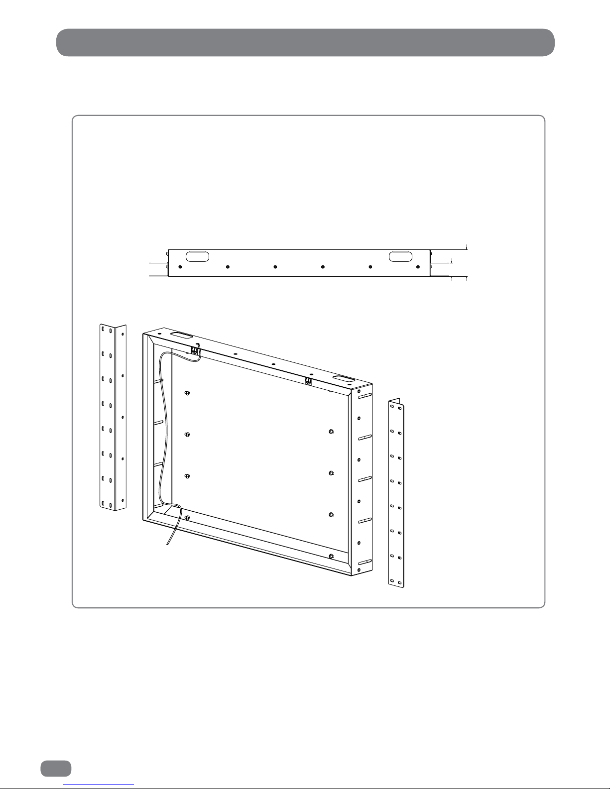
Within the back box there are two right-angled brackets and fixing screws. Screw the brackets to
the outside of the back box but be aware these will need to be loosened to allow adjustment of
the back box when fitted into the wall.
As shown below, the brackets allow 34 mm of forwards/backwards adjustment so that the front
of the back box can fit flush with the tiled surface. Any additional adjustment needed to ensure
the front of the back box is flush with the tiles should be considered before fitting the back box.
70
34
The range of adjustment available with the back box brackets
The qualified
electrical installer
must use one of the
earthing screws as
an earth point to
earth the unit to
ground.
The lead used must
be terminated with a
ring terminal, which,
together with the
earthing cable’s ring
terminal, is fastened
using the supplied
locking washer and
screw.
Lead to electrical earthing point
(not supplied)
Page 9
7
Recess Dimensions
Installation and positioning
Cut the required recess, with the depth measured from the front face of the tiles.
Fit the back box into the wall ensuring that the earth leads are at the top.
To adjust the position of the back box loosen the screws, which attach the left and right hand
brackets to the back box, these screws are located each side within the back box. Ensure that
you do not fully unscrew the fasteners to avoid detaching the brackets from the back box.
Adjust the alignment of back box making sure the front edge of the back box sits flush with the
front face of the tiles.
Secure all screws to lock the back box into position.
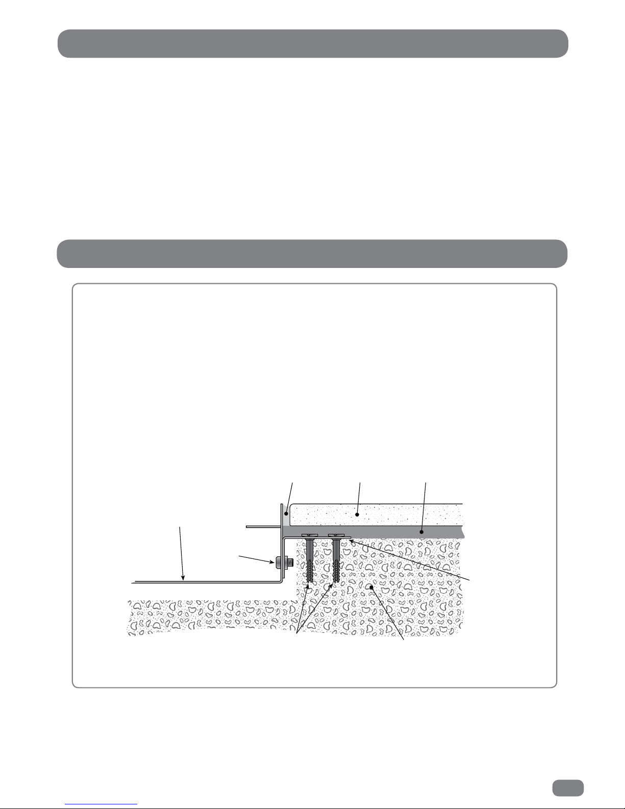
Note: Removal of the front glass requires a force of 300 Kg when using a glass suction lifter.
The box must be secured to the wall so that it is able to withstand the pulling force.
Wall
Flange
Grout Tile adhesiveTile
Back box
Plug and screw
or wall bolt fixings
Machine
screw
Example of a back box installed in a ‘solid’ wall
22" TileVision
590mm x 381mm x 75mm depth
from the front face of the tiles.
26" TileVision
703mm x 455mm x 75mm depth
from the front face of the tiles.
First Fix Kit – Installing the Back Box
®
®
Page 10
8
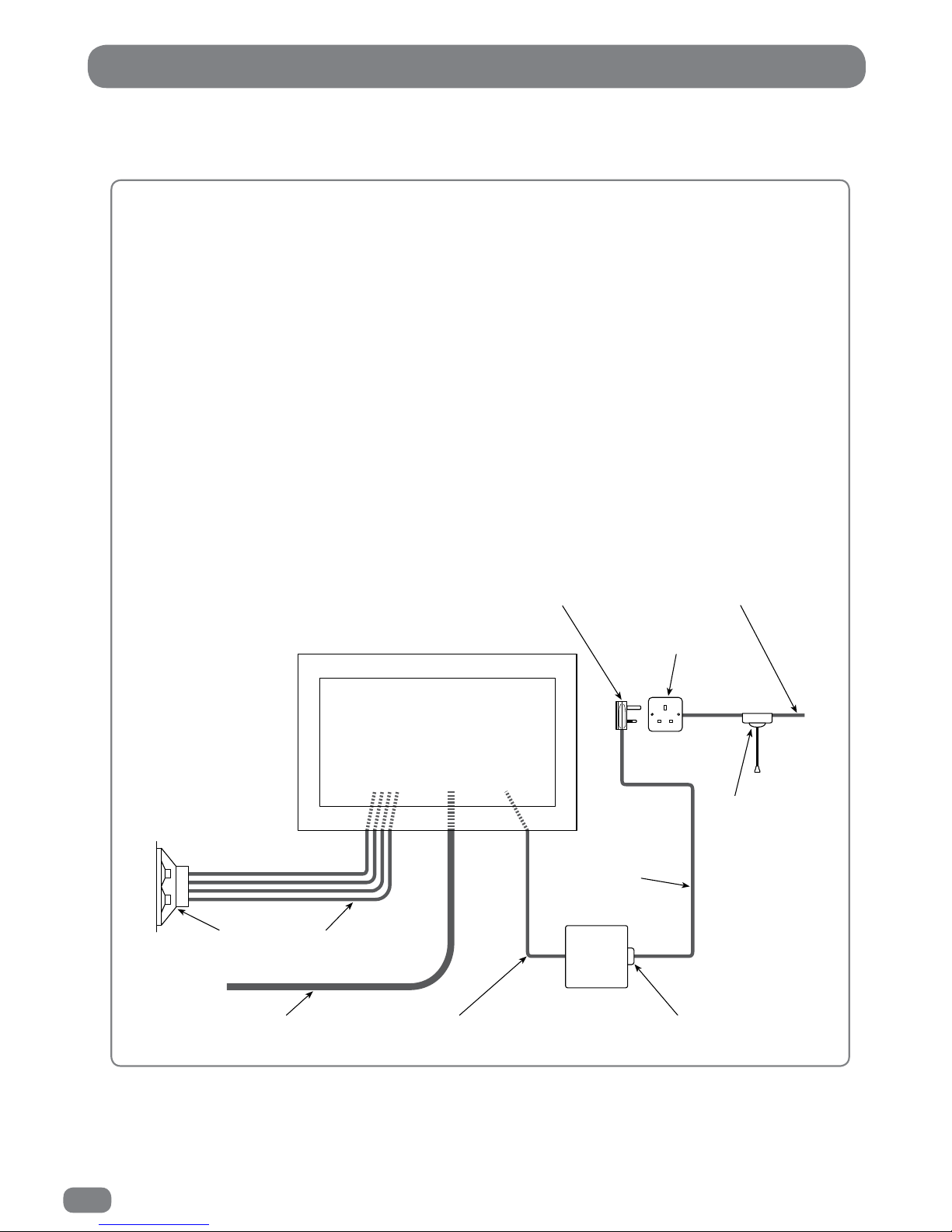
First Fix Kit – Cabling
Please note – All electrical installation should be carried out by a fully qualified
electrician and all fire & safety regulations must be obeyed.
Power Requirement (Mains)
TileVision® requires a 13 amp socket outlet connected to a 240 V mains supply via a readily
accessible isolation switch. This electrical installation must include an all-pole switch with a
contact separation of at least 3 mm in each pole. Both the socket and the isolation switch must
conform to the latest safety specification and be protected via an RCCD device or similar. This
socket must be fitted in a dry area, away from any moisture (usually in the ceiling). The mains
plug must be fitted with a 5 amp fuse..
TileVision® Power Supply (24 V)
The 24 V power supply unit is not waterproof and so must be positioned in a dry, well-ventilated
area away from any water or moisture. It is fitted with an integral 4 metre lead to feed the
TileVision®. This lead must not be cut, shortened or lengthened – this could potentially damage
the power supply unit and the TileVision® and have implications regarding safety.
Ensure the remote isolation switch is off and connect the power supply mains lead to the 24 V
power supply unit. Connect the mains plug in to the mains socket.
Feed the cable from the power supply unit in to the back box. Make sure there is approximately
400 mm of slack at this end of the cable.
Mains plug 240V mains supply
Isolation
switch
Mains power
supply cable
IEC320 socket
24V DC
power
supply
Integral power
supply cable (4m)
TV aerial cable
(not supplied)
Speaker
cables
Mains socket
Stereo
speaker
Page 11
9
Please note – All required cabling for additional inputs must be installed during the
installation of the back box.
First Fix Kit – Cabling
TV Aerial Feed
Pass the aerial lead in to the back box and leave approximately 400 mm of lead loose in the back
box. Terminate the aerial lead with a standard 75 Ω coax termination.
A TV Distribution Amplifier may be required if you are in an area of weak signal or if other
televisions are already being fed from the aerial. If in doubt, consult a qualified aerial technician.
If the TileVision® is to be used with a Sky™ digital receiver which has two RF outputs, the channel
can be changed on the Sky™ receiver using the TileVision® learning remote control via the
TileVision®. To use this facility install a good quality coaxial cable that runs directly from the RF2
outlet of the Sky receiver, or from the outlet of a Remote-Link amp, in a continuous uninterrupted
run.
The TileVision® will accept additional inputs from many sources and can be integrated with home
automation and interactive hotel TV systems. See pages 14 to 18 for specific information.
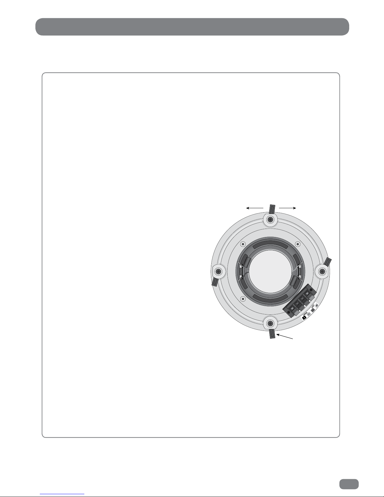
Installing the supplied single stereo speaker
To fit the speaker cut a single 208 mm diameter hole in the
ceiling using the template supplied. Position the template a
minimum of 16 mm from any joists. Do not to cut through
any joists, cables or pipes, etc.
A four and a half metre length of four core speaker
cable is supplied with the speaker. Feed one end of
the speaker cable in to the back box, leaving 400 mm
of cable protruding in to the back box. The cable
should then be run from the TileVision® back box to
the position of the speaker leaving any surplus cable in
the ceiling space.
The speaker terminals on the TileVision® and on the
stereo speaker are colour coded to match the colours of the
supplied four core speaker cable. To ensure that the stereo
speaker is connected correctly the individual leads must be
connected to their matching colours on both the TileVision® and the stereo
speaker.
To connect the speaker cable to the ceiling speaker lift one of the lugs to open a terminal and insert
the appropriately coloured conductor. After releasing the lug give the lead a slight pull to make sure
that the lead is gripped correctly. Connect all of the leads in the same manner.
Loosen all four screws by turning them counter clockwise until the clamps can move freely. Do not
remove the screws. Install the speaker in to the precut hole and orientate the speaker so left audio
will be heard on the left and right audio heard on the right. Turn the clamp screws clockwise until
they are tightened and the speaker is held firmly. Insert the speaker grille by gently pressing it into
place. The grille will fit tightly without causing any vibration.
Speaker fixing clamp
Left audio
Right audio
Page 12
10
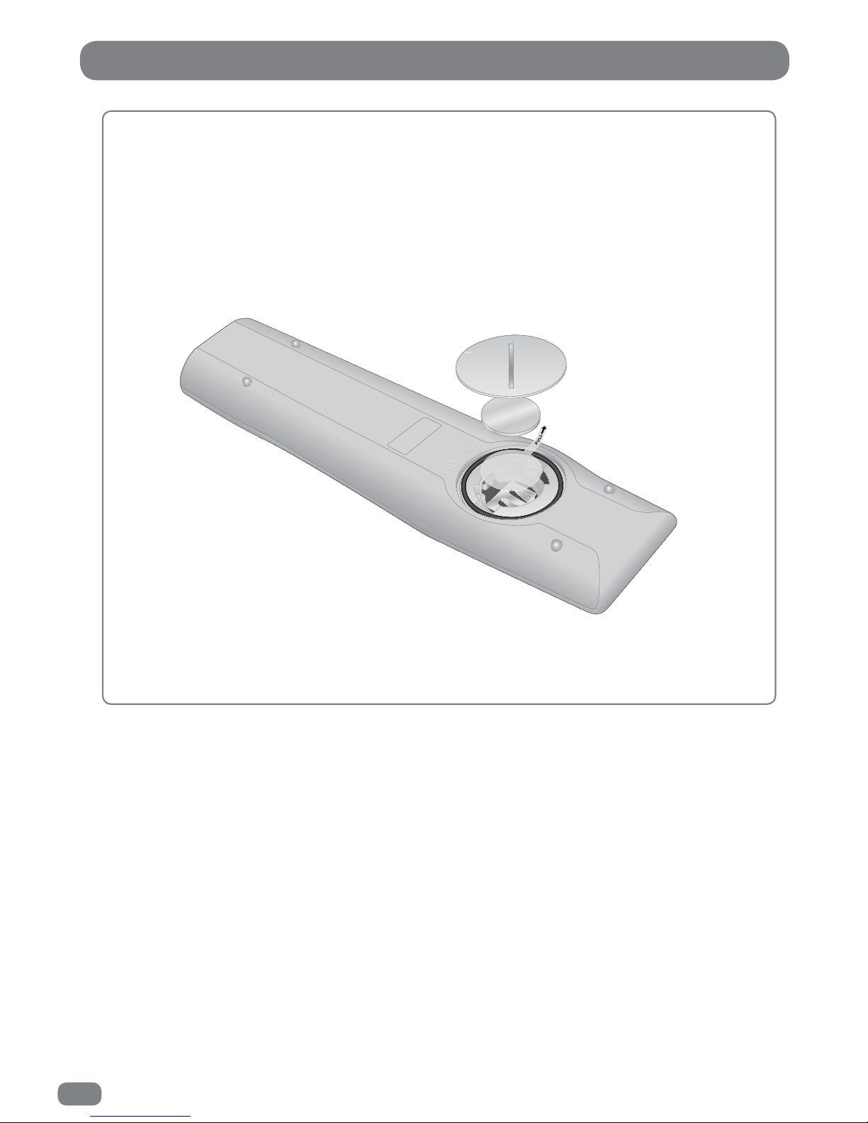
The Splashproof Remote Control
Before the splashproof remote control can be used the insulating plastic film must be removed
from beneath the battery.
Place the remote control face down on a horizontal flat surface and use the opener to release the
battery compartment cover by rotating it in an anti-clockwise direction. Set the battery cover and
opener to one side.
Rest one finger lightly on the battery and pull the printed tag to ease the insulating film from
underneath the battery. Try to avoid touching the black O-ring as it is coated in light grease.
Replace the battery cover and lock it back in place using the opener.
Li Thiu m Ce ll
CR 2032
3V
Li Thiu m Ce ll
CR 2032
3V
Remote control with battery cover removed
Replacing the Battery
Place the remote control face down on a horizontal flat surface and use the opener to release the battery
compartment cover by rotating it in an anti-clockwise direction. Set the battery cover and opener to one
side.
Carefully remove the old battery and dispose of it safely.
Observe the polarity.
Do not short circuit the battery.
The battery of remote control shall not be exposed to excessive heat such as
sunshine, fire or the like.
Try to avoid touching the black O-ring as it is coated in light grease.
Insert the new CR2032 battery with the positive (+) side upwards. Replace the battery cover and lock it
back in place using the opener.
Page 13
11
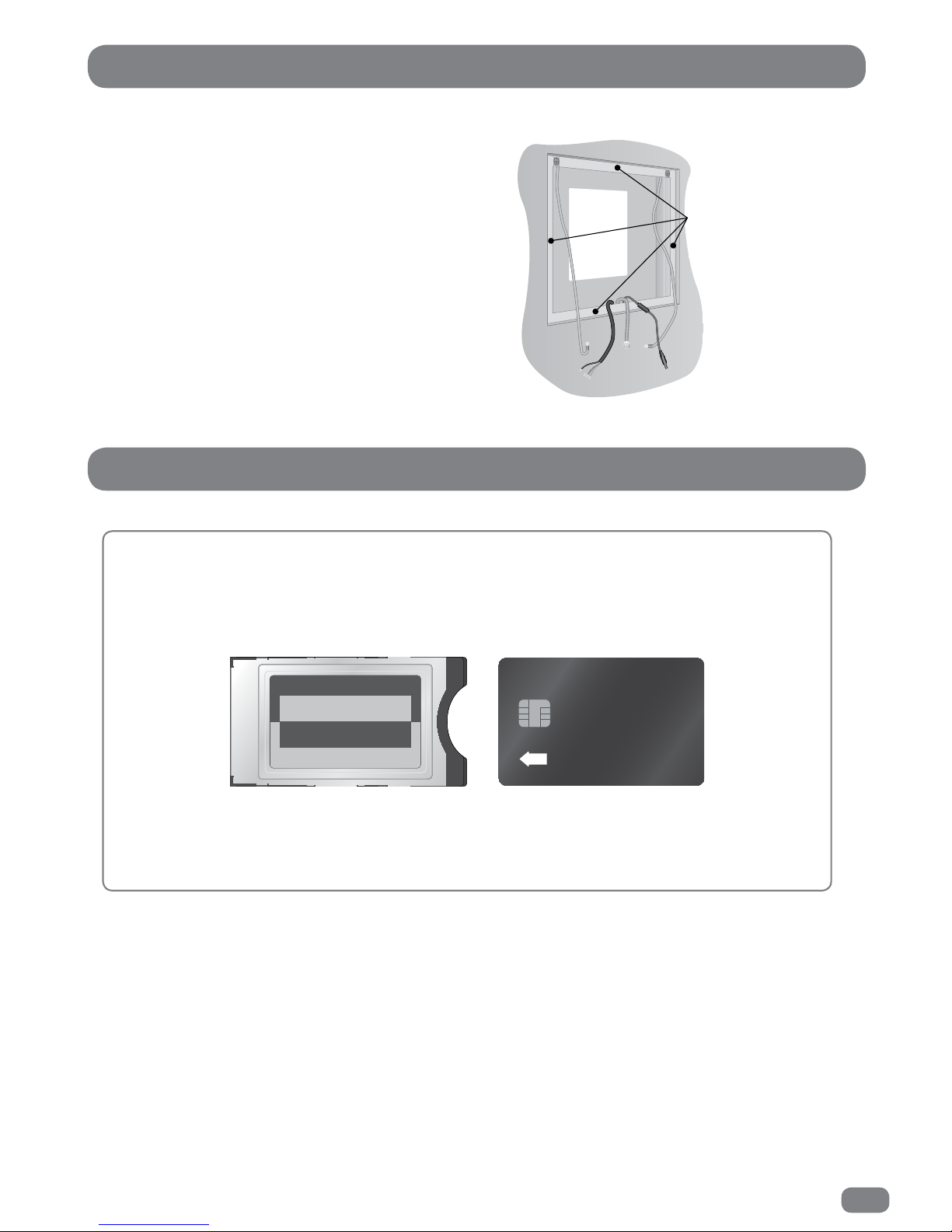
Checking the back box prior to installation
Before commencing installation of the TileVision® make
sure that all of the required input cables are present within
the back box.
It is important to ensure that the flange inside the back box
is thoroughly cleaned using isopropyl alcohol and allowed to
dry.
Checking the Back Box
The Common Interface (CI) Port
If a Conditional Access Module (CAM) is being used to add channels to the TileVision® the CAM
should be inserted into the CI Port of TileVision® with the power disconnected
.
Take a note of the Smart Card’s serial number and follow the CAM/Smart Card manufacturer’s
instructions to insert the Smart Card into the CAM and access the service.
The Smart Card must be activated in accordance with its service provider’s instructions before
installation is completed and the TileVision® is sealed.
INSERT
all of the
flange must
be cleaned
Page 14
12
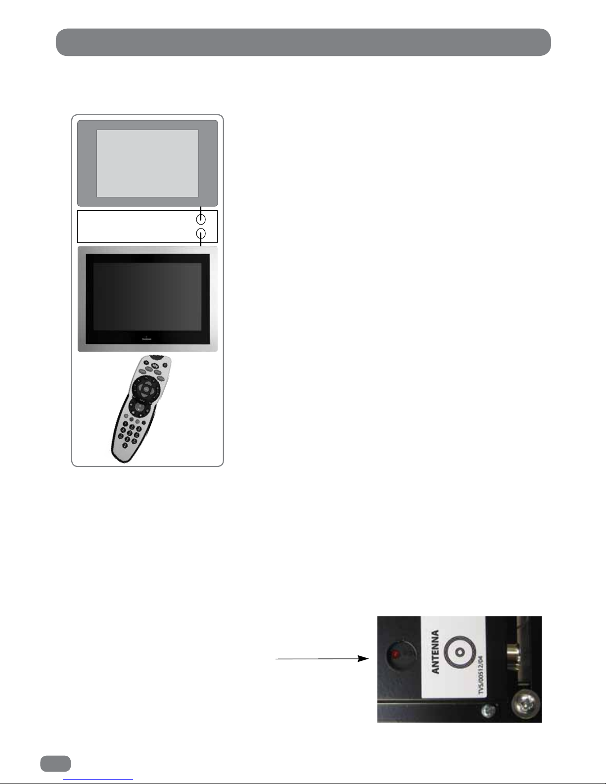
If the TileVision® is used with a Sky™ receiver, the channel can be changed on the Sky™
receiver using the Sky™ remote control via the remote sensor on the TileVision®.
Sky™ Remote Control Link Setup
Preparation to use this facility should have been completed during
the installation of the first fix assembly (see page 9).
It is advisable to setup the Sky™ receiver so that it can be
controlled via the TileVision® before the TileVision® is installed.
The red LED on the TV Link (that is fixed to the TileVision®) will
light when correctly connected to and powered by the Sky™
receiver. This is checked when connecting the aerial lead to the
TileVision®.
The connection to the Antenna/RF connectors on the TileVision®
and the Sky™ receiver must be made with both the TileVision®
and the Sky™ receiver disconnected from the mainssupply. Use
good quality coax cable either directly from the RF2 outlet of the
receiver or the outlet of a Remote-Link amp in an uninterrupted
run .
Once the connections have been made, the Sky™ receiver must
be setup to supply power to the RF2 socket as detailed below.
To set-up the Sky™ receiver to work with the
TileVision® the Sky™ remote control must be used
via the main TV (TV 1).
1
On the Sky™ remote control press
SERVICES
to show the
SERVICES menu.
2
Press the 4 button for the SYSTEM SETUP menu.
3
Press the 0 button, then the 1 button, then the
select
button,
in sequence, to display the INSTALLER SETUP menu.
4
Press the 4 button to select RF OUTLETS.
5
Press the
down
arrow to select RF Outlet Power Supply and
press the
left
or
right
arrows to change the setting to ON.
6
Press the
down
arrow to select Save New Settings and press
select
to save the settings.
7
Press the
sky
button to return to the previously viewed
channel.
Red LED indicator will light
when power is received from
the Sky™ RF2 outlet
Sky™ digital receiver
RF 1
RF 2
TV 1
To set up the TileVision
remote control to operate
the Sky™ receiver see page
62 (Entering a Brand Code).
Page 15
13
Note: All connections should be made with the remote isolation switch for the TileVision
®
set
to OFF.
Installing the TileVision® – Initial Connections
Earthing Points
Introduce the lower front edge of the unit into the back box
and fit the earth cables to the two earthing screws as
indicated by the green labels on the rear of the TileVision®.
The earth cables are electrical connections and
must not
be used to support the weight of the TileVision®.
Power Socket
The Power connector is located at the extreme left of the connection array.
Speaker Connections
The supplied stereo speaker should be connected after the earthing straps are connected to the rear of the
TileVision® as detailed above.
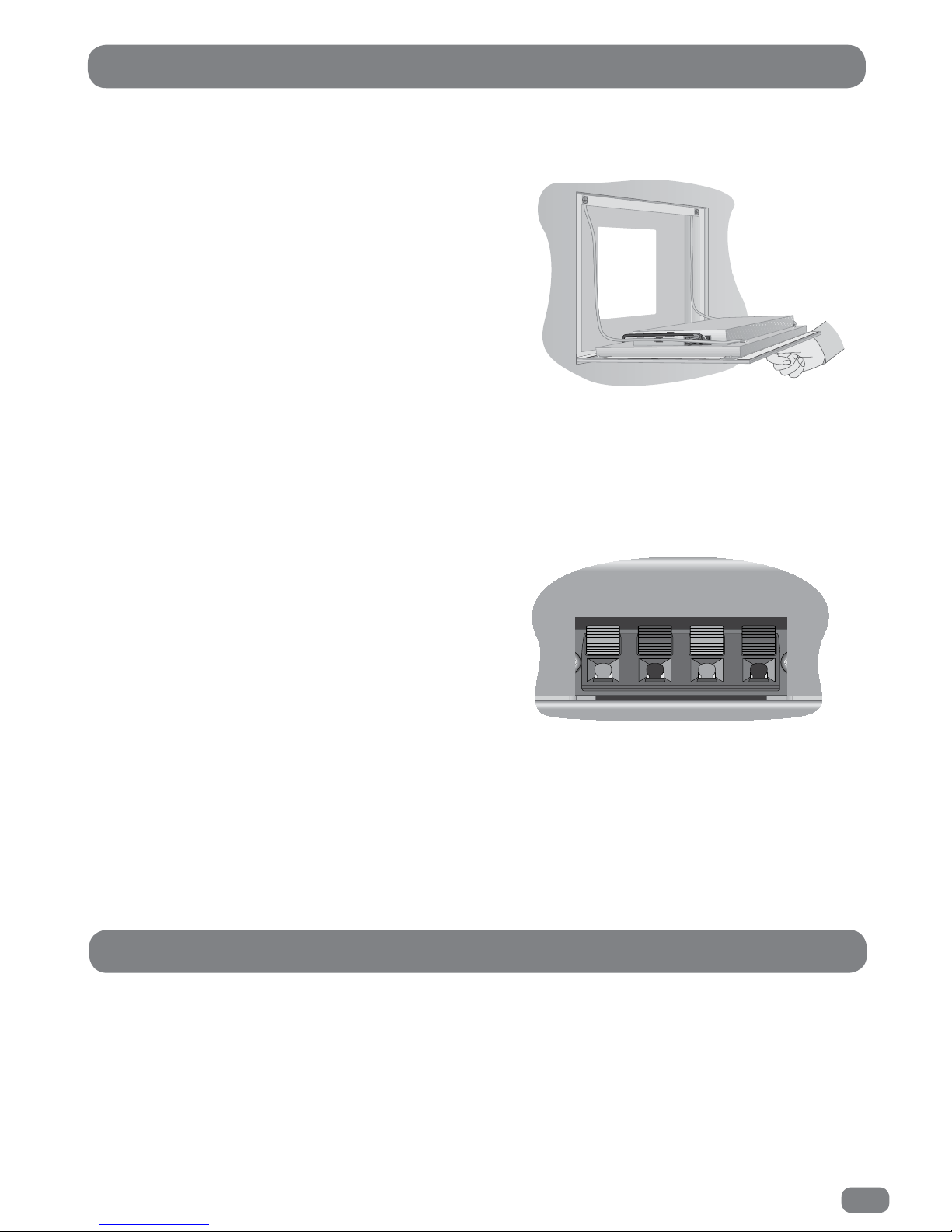
The speaker terminals on the TileVision® and on the stereo
speaker are marked with coloured dots which match the
colours of the supplied four-core speaker cable. To ensure
that the stereo speaker is connected correctly the
individual leads should be connected to their matching
colours on both the TileVision® and the stereo speaker.
The speaker connection block is found on the left of the rear
of the TileVision®. Lift one of the lugs, push one conductor
of the speaker lead into the connector, release the lug and
give the lead a slight pull to make sure that it is gripped correctly. The other wires should be connected in
the same way.
If two separate speakers and alternative speaker cables are being used, the conductor with the stripe
should be connected to the negative terminal (L– or R–) and the plain conductor should be connected to the
corresponding positive terminal (L+ or R+). The connections to the speakers terminals should be made in
the same way – striped conductor to the negative terminal and plain conductor to the positive terminal.
Earth lead
connections
L–L+ R+ R–
The speaker connection block
USB Memory Stick (Flash Drive)
If the timer recording, time shift recording functions, or the digital media player is to be used, a USB
memory stick (flash drive) must be installed. If only one USB memory stick (flash drive) is to be installed, it
is recommended that it is fitted to the USB 1 position.
Page 16
14
All connections must be made before sealing the TileVision® into the back box.
TileVision® Connectors
To view television channels correctly, a signal must be received by
the TileVision® from one of the following sources:
an outdoor antenna
a cable television system
a satellite receiver.
Antenna Feed
Connect the antenna or input cable to the 75Ω coaxial connector
on the rear of the TileVision®.
Picture quality is determined by the signal level, it is
recommended that a qualified aerial technician is consulted.
Antenna input on
the TileVision
®
Cable Television
Network
or
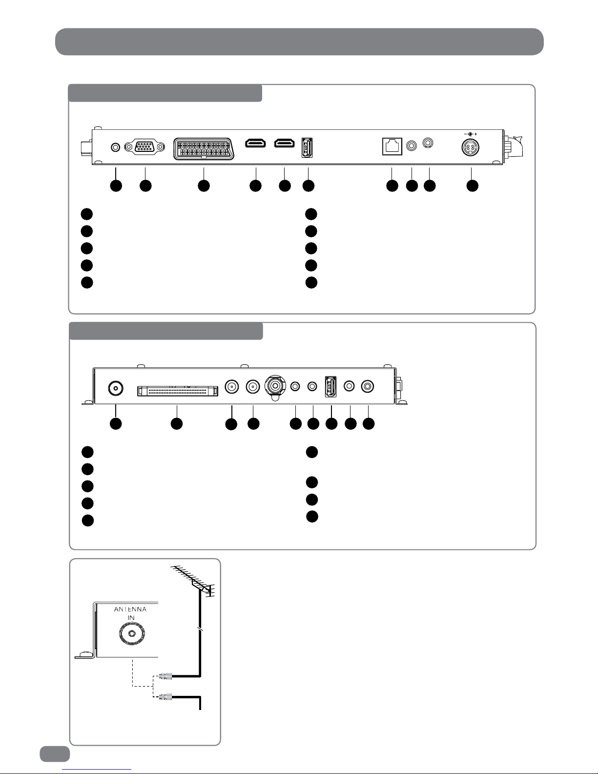
Base Connector Array
USB 1(USB Memory Stick / Flash Drive)
RJ12 – for Hotel TV System Integration
Infrared Link – In
Infrared Link – Out
DC 24V Power In
6
7
8
9
10
1 2 3 4 5 6 7 8 9 10
PC AUDIO
IN
VGA IN
SCART IN
HDMI 1 IN
HDMI 2 IN
USB 1 IN
RJ 12
IR Link
OUT
IN
24v DC
3.75 A
PC Audio In
VGA Input (D-SUB)
EURO-SCART
HDMI 1 (High Definition Multimedia Interface)
HDMI 2 (High Definition Multimedia Interface)
1
2
3
4
5
Side Connector Array
Composite Video Input (CVBS), Left & Right
Audio Input
USB 2 (USB Memory Stick / Flash Drive)
Audio Out (headphones)
SPDIF Out
6
7
8
9
1 2
3
4 5 6 7 8 9
ANTENNA
IN
CI PORT
LOOP OUT
SATELLITE
IN
COMPONENT
IN
AV &
L/R AUDIO IN
USB 2 IN
EARPHONE
OUT
SPDIF OUT
Antenna Input 75 Ω
CI Port for Conditional Access Module (CAM)
Satellite In
Satellite (Loop Out)
Component Video Input (Y, Pb (Cb), Pr (Cr)
1
2
3
4
5
Page 17
15
All connections must be made before sealing the TileVision® into the back box.
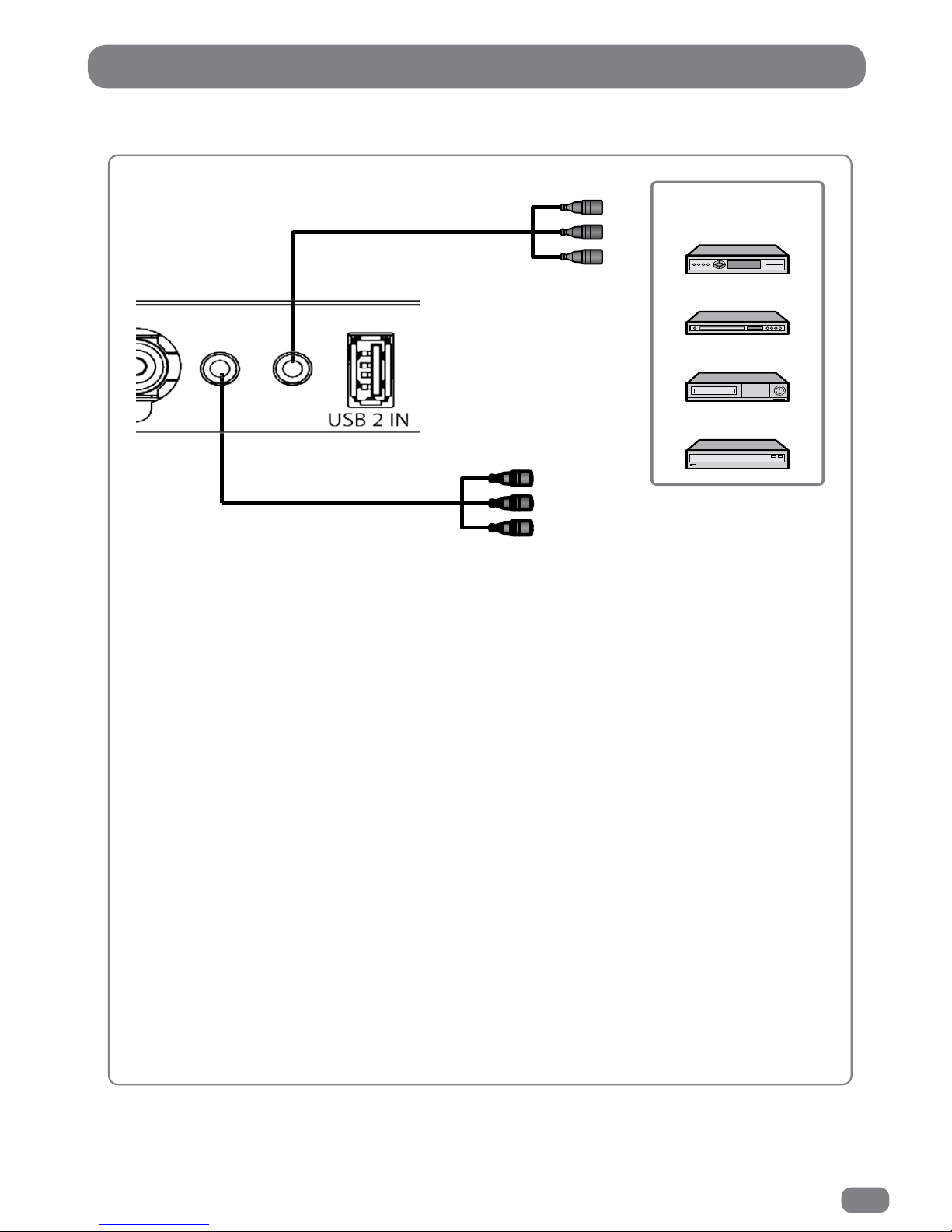
The Component and Composite Video Connectors
(A) For Component Video
1
Connect the Left and Right Audio connectors (white and red) of the COMPOSITE video jack lead
to the corresponding connectors on the external equipment such as a satellite receiver or DVD
player.
Connect the video connections of the COMPONENT jack lead Y, Pb and Pr Inputs (green, blue and
red) to the corresponding connectors on the external equipment such as a satellite receiver or
DVD player.
2
If the external equipment only has a mono audio connector, it should be connected to the left
(white) connector of the Audio Input.
(B) For Composite Video
1
Connect the Left and Right Audio connectors (white and red) of the COMPOSITE video jack lead
to the corresponding connectors on the external equipment such as a satellite receiver or DVD
player.
Connect the CVBS Composite connector (yellow) of the COMPOSITE video jack lead to the
corresponding connectors on the external equipment such as a satellite receiver or DVD player.
2
If the external equipment only has a mono audio connector, it should be connected to the left
(white) connector of the Audio Input.
AV & L / R AUDIO
COMPONENT
Video Game Console
VCR
DVD Player/Recorder
Satellite Receiver,
Cable Box or Hard Disk
Recorder
(A) for Component Video
(B) for Composite Video
Page 18
16
All connections must be made before sealing the TileVision® into the back box.
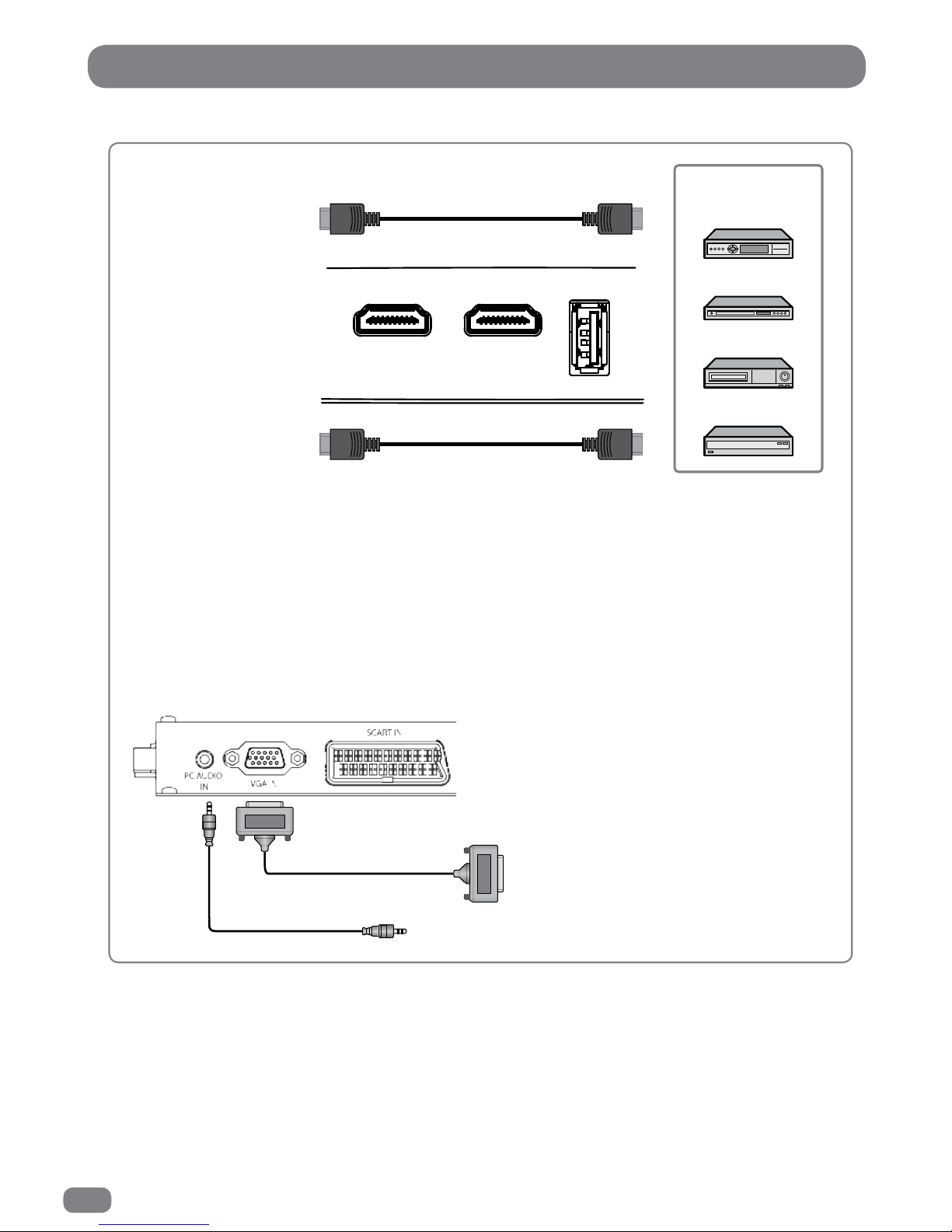
The HDMI and S-VIDEO Connectors
HDMI Connections
Connect the HDMI cable to the HDMI connection on the TileVision® and the HDMI connection on the
external equipment such as a satellite receiver or DVD/Blue-ray player.
PC Connections
To use PC RGB, connect the PC RGB connector of the TileVision
®
to the PC’s RGB connector and
connect the PCAudio In connector on the TileVision® to the PC’s audio out connector.
HDMI 1 IN
HDMI 2 IN
USB 1 IN
Video Game Console
VCR
DVD Player/Recorder
Satellite Receiver,
Cable Box or Hard Disk
Recorder
PC RGB Video
PC Audio
Page 19
17
The SCART Connector
All connections must be made before sealing the TileVision® into the back box.
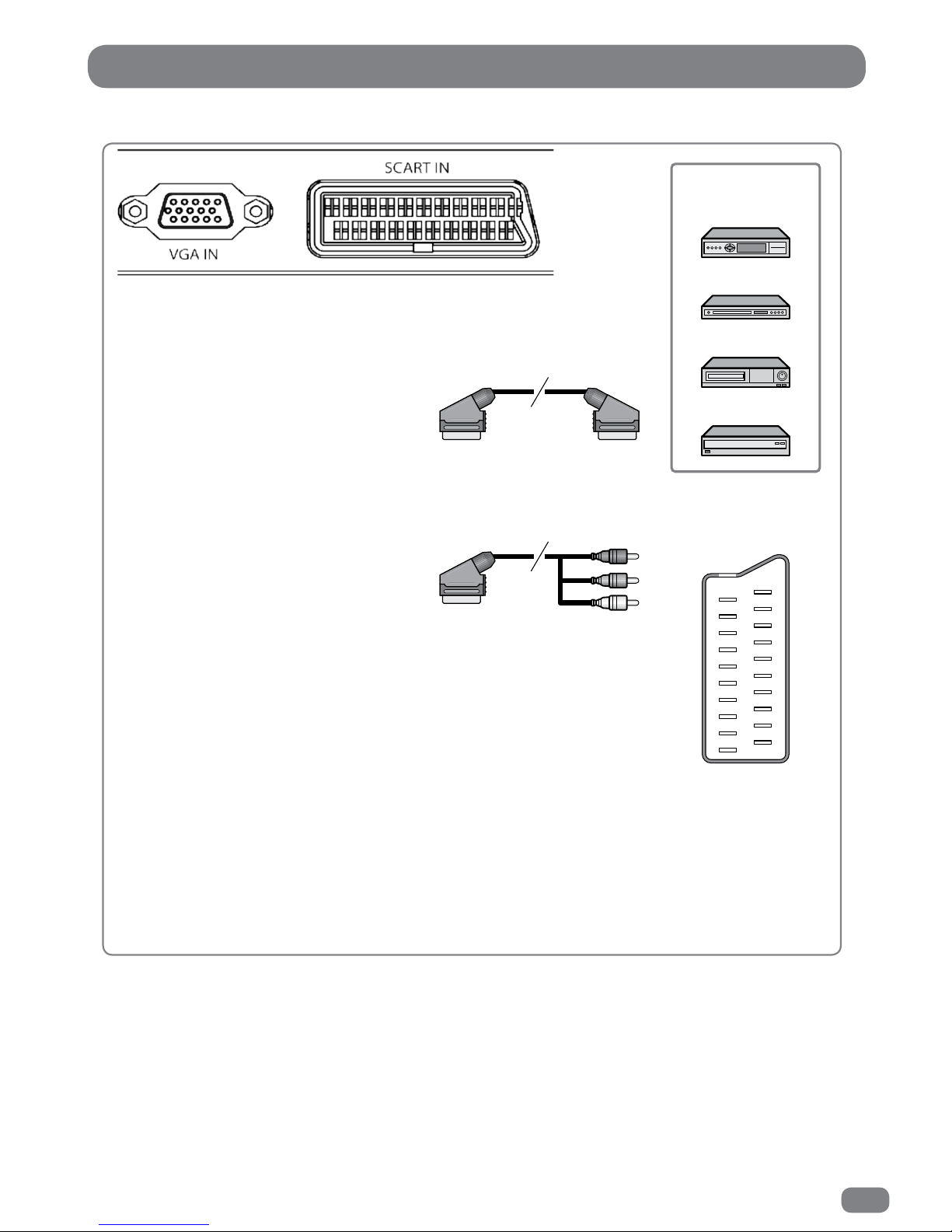
The EURO-SCART connector can be used with equipment which has RGB or composite video inputs
and outputs. A VCR, satellite or cable receiver, DVD player, or video game console should be
connected using the EURO-SCART connection.
The EURO-SCART socket is fully wired as shown above.
The audio output from the EURO-SCART can be connected to a separate amplifier to allow
integration with a multi- room audio video system. This should be carried out by a qualified
engineer.
SCART Connection Reference
Pin Name Description
1 AOR Audio Out Right
2 AIR Audio In Right
3 AOL Audio Out Left + Mono
4 AGND Audio Ground
5 BGND RGB Blue Ground
6 AIL Audio In Left + Mono
7 B RGB Blue
8 SWTCH Audio, RGB switch,16:9
9 GGND RGB Green Ground
10 CLKOUT Clock Out
11 G RGB Green
12 DATA Data Out
13 RGND RGB Red Ground
14 DATAGND Data Ground
15 R RGB Red
16 BLNK Blanking Signal
17 VGND Composite Video Ground
18 BLNKGND Blanking Signal Ground
19 VOUT Composite Video Out
20 VIN Composite Video In
21 SHIELD Chassis Ground, Cable Shield
Video Game Console
VCR
DVD Player/Recorder
Satellite Receiver,
Cable Box or Hard Disk
Recorder
19
17
15
13
11
9
7
5
3
1
20
18
16
14
12
10
8
6
4
2
21
(A) SCART to SCART connector
(RGB Video + Audio L/R or
Composite Video + Audio L/R)
(B) SCART to RCA connectors
(Composite Video + Audio L/R)
SCART Pinouts
(solder side view)
Page 20
18
All connections must be made before sealing the TileVision® into the back box.
The IR Link, RJ12 and RS-232 Connectors
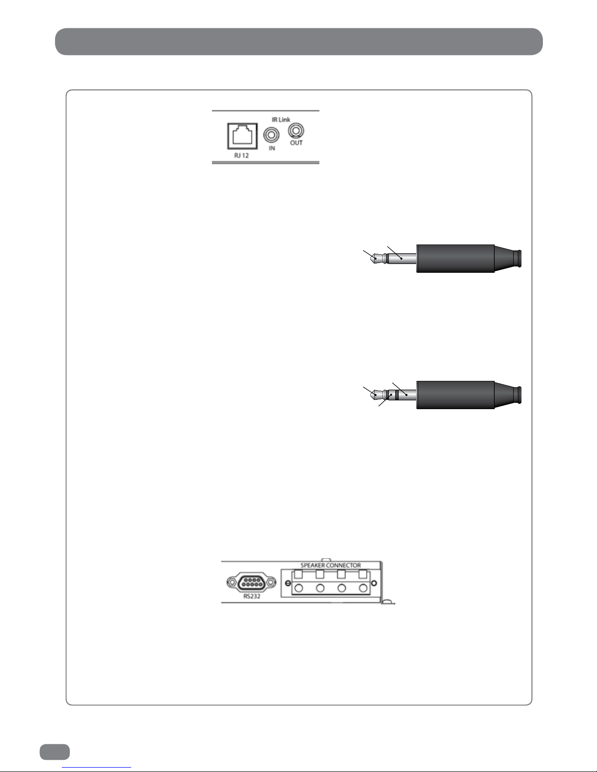
IR Link Out
The IR Link Out is a 3.5 mm mono jack socket. The IR signal sensed by the TileVision® is outputted
from this socket to an IR emitter. This will enable the remote control of external equipment, such as a
DVD player, from the TileVision®.
IR Link Out Connections – IR Emitter
IR emitter LED positive terminal to the Tip.
IR emitter LED negative terminal to the Sleeve.
IR Link In
The IR Link In is a 3.5 mm stereo jack socket. This socket allows an auxiliary IR sensor to be
connected to the TileVision® to enable remote control of the TileVision® from a different point other
than the front of the TileVision®.
IR Link In Connections – IR Receiver
The TileVision® interface will supply +5v DC to power
the IR sensor.
IR sensor +5v DC terminal to the Tip.
IR sensor signal output terminal to the Ring.
IR sensor negative terminal to the Sleeve.
3.5 mm mono jack plug
Tip
Sleeve
Ring
3.5 mm stereo jack plug
Tip
Sleeve
RJ12 Connector
This connector is for Hotel TV System Integration. The RJ12 allows command codes to pass to and
from the TileVision®. The RJ12 pin assignment is internally configurable, to allow the connection of
various Hotel TV Systems.
RS232 Port
The RS232 control port enables the
TileVision® to be controlled from a home automation
control system.
For detailed information on the IR Link, RJ12 and RS-232 connections and
the relevant control signals see the TileVision® Interface Connections pdf
on the TileVision® web site (www.tilevision.tv – support – user support).
Page 21
19
Ensure that the TileVision® does not get wet until it is fully sealed.
Installing the TileVision® – Setup and Tuning
When the connections have been made as shown on pages 8 to
18 it is time to install the TileVision® into the back box.
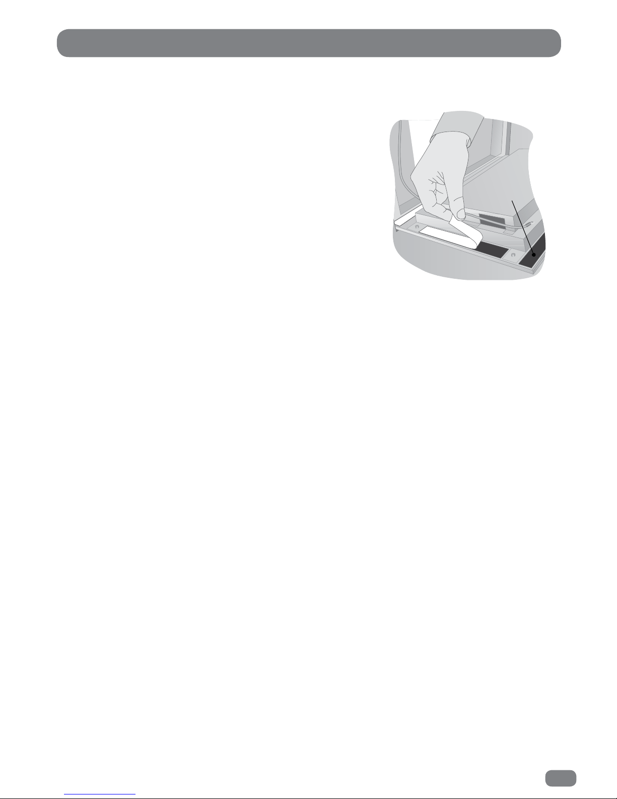
Remove the soft adhesive protector from the top length of Velcro‚
and press the TileVision® into the back box. It may be found
necessary to adjust the position of the cables in order to achieve a
good fit.
The installation must comply with all relevant electrical safety
regulations before the mains supply is turned on using the remote
isolation switch. The TileVision® should now show a red indicator
light showing that it is in standby mode. Ensure that the
TileVision® does not get wet until it is fully sealed.
only the top
strip is removed
before tuning
Initial Tuning
Press the POWER button on the remote control to switch the TileVision® on from standby. The LED indicator
will show green and the OSD Language menu will be displayed within twenty seconds.
The on-screen menus can be in any of the following twenty two languages: Český, Dansk, Deutsch, English,
Español, Ελληνικά, Français, Hrvatski, Italiano, Magyar, Nederlands, Norsk, Polski, Portugês, Pyccкий,
Româneste, Slovenščina, Srpski, Suomi, Svenska, Български, Slovak.
1
Press the
34
or 56 buttons to highlight the required language.
2
Press the OK button to select the language.
If tuning of DTV / ATV is required follow the instructions 4 to 8 on page 25 (Tuning the
TileVision®
DTV / ATV) .
If tuning of DVB-C is required follow the instructions 4 to 10 on page 25 (Tuning the
TileVision®
DVB-C) .
If tuning of satellite is required press the EXIT button. Select Satellite (satellite) as the source (see
the instructions, Selecting a Source page 24). Set up and scan the satellite (see the instructions,
Tuning the
TileVision® Satellite (satellite) pages 26 to 28).
Page 22
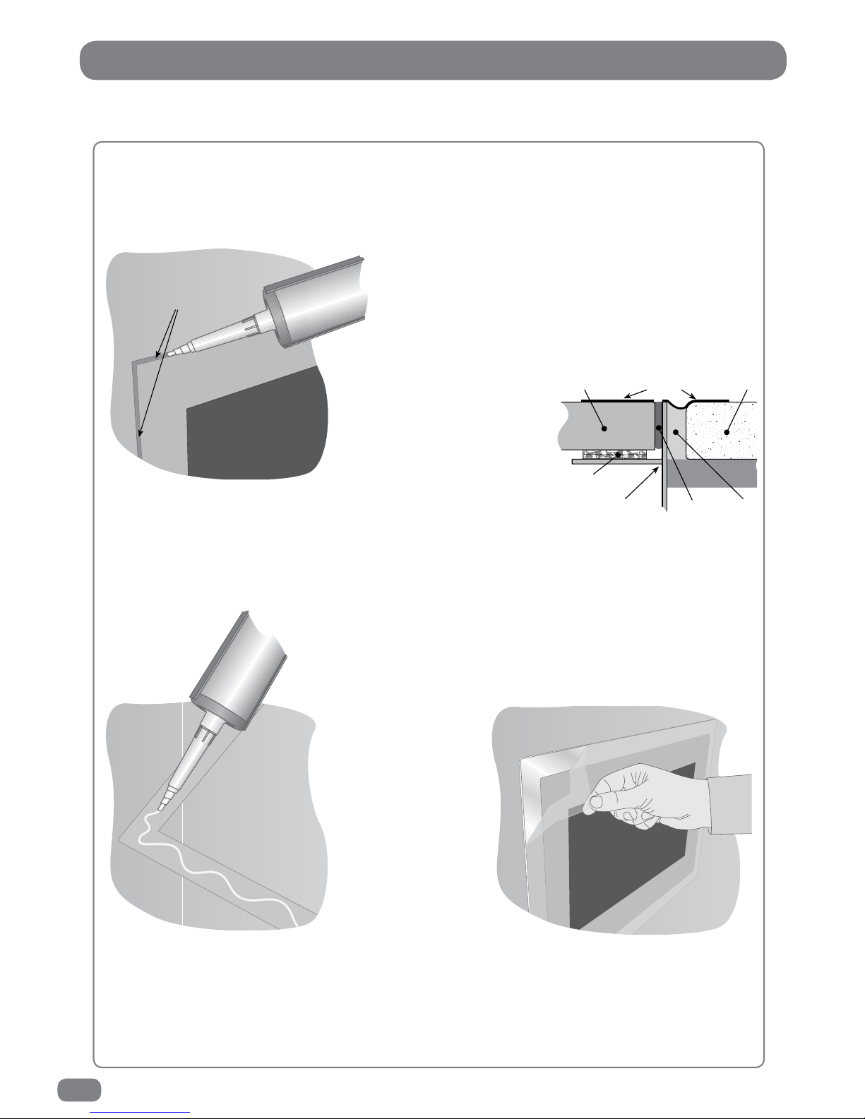
20
Note: It is the installer’s responsibility to ensure that the TileVision® is
installed and sealed correctly, failure to do so will invalidate the guarantee.
Installing the TileVision® – Sealing
Sealing the TileVision
®
When correct function has been confirmed, switch the TileVision® to standby and set the isolation
switch to off. Apply clear silicone sealant to the joint between the sides of the back box and the sides
of the TileVision®. Ensure that the sealant is worked into the space evenly and is applied without any
gaps, bubbles or voids. Wipe any excess sealant away and
check for any imperfections. Rectify any errors as
necessary.
This seal is essential for the reliable and safe
operation of the TileVision® and must be
completely waterproof.
Sealing Tip
: To achieve a neat
seal apply lengths of masking
tape around the TileVision®
glass screen and the
surrounding tiles. Leave
sufficient gap to apply the
sealant around the joint between
the sides of the back box and TileVision®.
Once the sealant has set and the masking tape removed the acrylic
surround can be fitted as shown below.
Fitting the mirrored acrylic surround
The mirrored acrylic surround is a cosmetic addition and has no bearing on
the integrity of the waterproof seal of the TileVision®.
If the surround is being fitted to the TileVision®, the same silicone
sealant used to seal the screen into the back box can be used to fasten
the surround to the wall.
Lay the surround on a
flat surface and apply
the sealant to the matt
grey surface as shown.
Once the sealant has
been applied, align the
surround with the
TileVision® using a
spirit level as a guide
and press the
surround firmly to
thewall.
After the sealant has set the protective film can be removed from the front of the surround.
Cleaning Instructions
To clean the glass and surround, use only a soft damp
cloth. Under no circumstances are abrasive cleaners to be used, failure to observe
this warning will invalidate the guarantee.
fill the space between the
edge of the TileVision
®
and the back box
Tile
Back box
Grout
Velcro
Masking tape
Silicone
Screen
apply the sealant
to the grey side of
the mirrored surround
Page 23
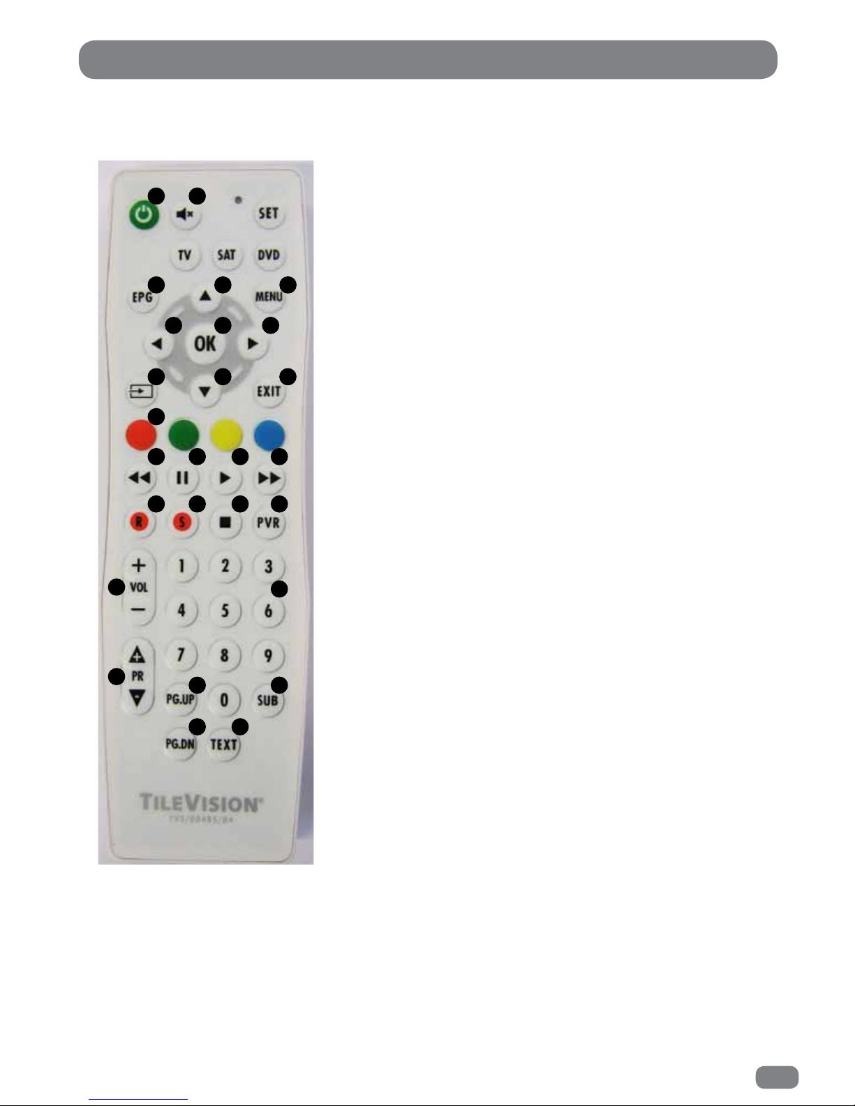
21
The Splashproof Remote Control
1 Power On/Off button
2
Mute button
3
Electronic Program Guide (EPG) button
4
Menu button
5
Up navigation button
6
Right navigation button
7
Down navigation button
8
Left navigation button
9
OK button
10
Source button
11
Exit button
12
Colour and Teletext buttons
13
Fast Reverse button
14
Pause button
15
Play button
16
Fast Forward button
17
Record button
18
Timeshift button
19
Stop button
20
Personal Video Recorder (PVR) button
21
Volume Up / Down buttons
22
Number buttons
23
Channel Up / Down buttons
24
Page Up button
25
Page Down button
26
Subtitles button
27
Text button
Make sure there are no
objects between the remote
control and
the TileVision®.
Do not place the remote
control near a heater.
A strong blow to the
remote control may cause
it not to operate.
1 2
3 45
8 9 6
10 7 11
12
13 14 15 16
17 18 19 20
21
23
22
24 26
25 27
Page 24
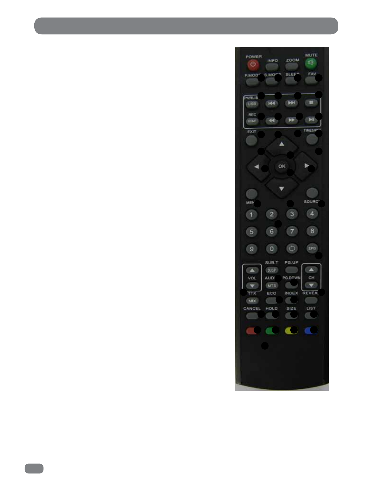
22
The Standard Remote Control
1 POWER On/Off button
2
INFO button
3
Zoom buttons
4
Mute button
5
Picture Mode button
6
Sound Mode button
7
Sleep button
8
Favourite button
9
Personal Video Recorder (PVR) List / USB button
10
Previous Chapter button
11
Next Chapter button
12
Stop button
13
Record / Home button
14
Fast Reverse button
15
Fast Forward button
16
Play / Pause button
17
Exit button
18
Timeshift button
19
Up navigation button
20
Right navigation button
21
Down navigation button
22
Left navigation button
23
OK button
24
Menu button
25
Source button
26
Number buttons
27
Back button
28
Electronic Program Guide (EPG) button
29
Volume Up / Down buttons
30
Sub.T / Sub.P button
31
AUDIO / MTS button
32
Page Up button
33
Page Down button
34
Channel Up / Down buttons
35
ECO button
36
LIST button
37 - 42
Teletext Control buttons
43
Colour and Teletext buttons
The standard remote control is not waterproof and
should not be splashed or immersed in water.
When installing or replacing the batteries:
Observe the polarity
Do not mix different battery types.
Do not short circuit the batteries.
The battery of remote control shall not be exposed to
excessive heat such as sunshine, fire or the like.
1 432
5 6 7
8
9 10 11 12
13 14
15 16
17 18
19
22 20
23
2124 25
26
29 34
30
32
3331
37 35 38 39
40 41 42 36
43
2827
Page 25

23
Please allow a minimum of five seconds after switching the TileVision® off before switching it on
again.
English is the preset language for the TileVision
®
. The language for on-screen menus can be
selected during initial set-up or at any time in the future.
1
To switch the TileVision® on, press the POWER button.
The LED indicator will show green and TileVision
®
will display a picture within twenty seconds.
2
To switch the TileVision® to standby, press the POWER button again. The LED indicator will show red to
indicate that the TileVision® is in standby mode
Switching the TileVision® On/Off
Selecting the On-screen Language
The on-screen menus can be in any of the following twenty two languages: Český, Dansk, Deutsch, English,
Español, Ελληνικά, Français, Hrvatski, Italiano, Magyar, Nederlands, Norsk, Polski, Portugês, Pyccкий,
Româneste, Slovenščina, Srpski, Suomi, Svenska, Български, Slovak.
To change the language used follow the sequence below:
1
Press the MENU button.
2
Press the 34 buttons to display the
OPTION
menu.
3
Press the 56 button to highlight OSD Language.
4
Press the OK button to display the OSD Language selection menu.
5
Press the 34 or 56 buttons to highlight the required language.
6
Press the MENU button to close the menu.
All the on-screen displays will now be in the chosen language.
The selected language applies to all modes.
Page 26
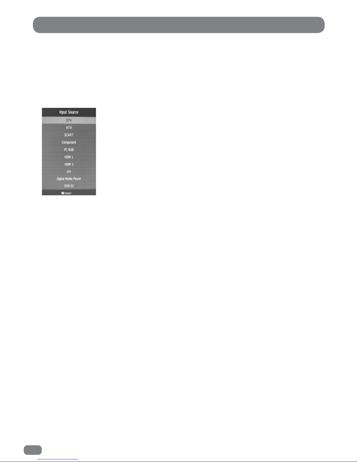
24
The Input Source list allows selection of the following: DTV (Digital Television), ATV (Analogue Television),
SCART, Component (Y,Pb,Pr), PC-RGB, HDMI 1, HDMI 2, AV, Digital Media Player and Satellite.
1
Press the Input button to display the
Input Source
list.
2
Press the Input button or the 56 buttons until the required source is selected.
3
Press the OK button to confirm selection of the chosen input and to clear the Input Source list from the
screen.
Press the EXIT button to close the Input Source list without selecting an alternative source.
If external sources have been connected to the TileVision
®
they may be viewed by selecting the
appropriate input.
Selecting a Source
Page 27

25
Tuning the TileVision® DTV / ATV
Select either DTV or ATV source see page 24
1
Press the MENU button. The CHANNEL menu will be displayed.
2
Press the 56 buttons to highlight Auto Tuning.
3
Press the OK button to display the Tuning Type menu (DVB Select Type).
4
Press the 56 buttons to highlight DVB-T / ATV.
5
Press the OK button to display the Tune Type menu.
6
Press the 34 buttons to select DTV & ATV tuning, or DTV tuning only or ATV tuning only. Once selection
has been made press the 6 button.
7
Press the 56 & 34 buttons to highlight the required country.
8
Press the OK button to start Auto Tune.
If a Sky™ box is being used as a source it should be switched on before tuning the
TileVision®. This will allow the TileVision® to tune to the Sky™ box correctly.
Select either DTV or ATV source see page 24
1
Press the MENU button. The CHANNEL menu will be displayed.
2
Press the 56 buttons to highlight Auto Tuning.
3
Press the OK button to display the Tuning Type menu (DVB Select Type).
4
Press the 56 buttons to highlight DVB-C.
5
Press the OK button to display the DVB-C Scan menu.
6
Press the 34 buttons to select Scan type between, Network Scan / Full.
6a
If Scan type is set to Full, Symbol(Ks/s) can be set. If Scan type is set to Network Scan,
Frequency, Network ID and Symbol(Ks/s) can be set. Press 56 buttons to select Frequency /
Network ID / Symbol(Ks/s). Press the 34 buttons to select between Auto / enter a value. The
value is entered using the number buttons on the remote control.
7
Press the OK button to display the Tune Type menu.
8
Press the 34 buttons to select DTV & ATV tuning, or DTV tuning only or ATV tuning only. Once
selection has been made press the 6 button.
9
Press the 56 & 34 buttons to highlight the required country.
10
Press the OK button to start Auto Tune.
Tuning the TileVision® DVB-C
Page 28

26
Tuning the TileVision® Satellite
Select Satellite source see page 24
1
Press the MENU button. The CHANNEL menu will be displayed.
2
Press the 56 buttons to highlight Dish Setup.
3
Press the OK button to display the Dish Setup menu.
4
Press the 56 buttons to highlight the required satellite. For UK Free To Air channels, select the satellite
marked Ku_TileVision (No 59).
5
Press the OK button, a RED tick will be placed by the side to indicate the satellite has been selected..
6
Press the 4 button to edit the satellite settings menu.
6a
Press the 56 buttons to highlight the setting to be adjusted.
LNB Type. Press the OK button to display the list of available options. Press 56 buttons
to highlight correct value. Press the OK button to set the value.
Recommended 09750/10750
6b
Press the 34 buttons to set the correct value for:
Recommended
LNB Power 13/18 V
22KHz Auto
ToneBurst None
DiSEqC1.0 None
DiSEqC1.1 None
Motor None
7
Press the BLUE button, the Channel Search menu will be displayed.
Refer to page 27 to set up the Channel Search options.
Page 29

27
Tuning the TileVision® Satellite
Channel Search Menu.
1
Press the 56 buttons to highlight Scan Mode.
2
Press the 34 buttons to set the scan mode to the required setting.
2a Default
Blind Scan
Network
3
Press the 56 buttons to highlight Crypted mode.
4
Press the 34 buttons to set the Crypted mode to the required setting.
4a
All Channels
FTA (Free To Air) Channels.
5
Press the 56 buttons to highlight Service Type mode.
6
Press the 34 buttons to set the Service Type mode to the required setting.
6a
All
DTV
Radio
7
Press the BLUE button, the Delete Satellite Channels confirmation menu will be displayed.
7a
Press the OK button to delete previous satellite channels and start a new scan.
Or press the EXIT button to start a new scan in addition to a previously scanned satellite.
Recommended setting for the Channel Search are:
Scan Mode Default.
Crypted All Channels.
Service Type All.
Page 30

28
Tuning the TileVision® Satellite (Transponders)
All setup values for each satellite must be entered before selecting individual transponders.
Select Satellite source see page 24
1
Press the MENU button. The CHANNEL menu will be displayed.
2
Press the 56 buttons to highlight Dish Setup.
3
Press the OK button to display the Dish Setup menu.
4
Press the 56 buttons to highlight the required satellite.
5
Press the OK button, a RED tick will be placed by the side to indicate the satellite has been selected..
6
Edit the satellite settings if required. Refer to pages 26 & 27.
7
Press the (non waterproof remote) ECO button (GOTO Transponder). A list of transponders will be
displayed.
8
Press the 56 buttons to highlight the required transponder.
8a
Transponder values can be edited. Press the GREEN button to display the transponder edit
menu.
8b
Press the 56 buttons to highlight the required setting.
8c
The values for Frequency & Symbol(Ks/s) is entered using the number buttons on the remote
control.
8d
Press the 34 buttons to set the value for Polarity.
8e
Press the OK button to save settings and exit the transponder edit menu.
9
Press the OK button (a RED tick will be placed by the side) to select the transponder to be scanned.
10
Repeat instructions 7 & 8 to select the required transponders to be scanned.
11
Press the BLUE button, the Channel Search menu will be displayed.
Refer to page 27 to set up the Channel Search options.
Page 31
29
Digital Television Manual Tuning
1
Set the source input to DTV see page 24
2
Press the MENU button to display the
CHANNEL
menu.
3 Press the
56
buttons to highlight DTV Manual Tuning.
4
Press the OK button to display the DTV Manual Tuning menu.
6
If there is a signal on the required channel press the OK button to start tuning the stations on
the selected channel.
The TileVision® will confirm that it is searching for channels.
After a short time the dialogue will show the number of DTV and Radio programmes that have
been tuned.
When the dialogue clears, the newly tuned station with the lowest number will be shown.
To tune additional programmes repeat steps 1 to 6.
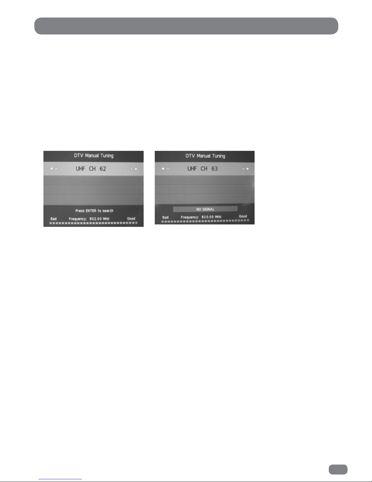
DTV Manual Tuning
5
Select the required channel (UHF 21–69) with the 34 buttons.
The DTV Manual Tuning menu will show if a signal is being received on the selected channel.
Good Signal on the selected channel
OK to tune.
No Signal on the selectedchannel
Do not tune.
Page 32

30
Analogue Television Manual Tuning
1
Press the MENU button to display the
CHANNEL
menu.
2
Press the 56 button to highlight the ATV Manual Tuning.
3
Press the OK button to display the ATV Manual Tuning menu.
4
Use the 34 buttons to select which programme to tune.
4
Press the 56 button to highlight
System
.
5
Select a
System
with the 34 buttons:
BG: Western Europe/Asia/Middle East/Africa/Australia
I: UK/Hong Kong/South Africa
DK: Russia/China/Eastern Europe
L: France.
6
Press the 56 button to highlight Search and then press
the 3
or
4 button to choose the search direction.
The search will stop when the next available station has
been tuned. To tune an alternative station press the 3
or
4
button to continue searching.
If necessary select
Fine-Tune
(56 )and adjust the tuning
with the 34 buttons to improve the picture or sound.
7
Press the Red button to save the settings.
8
Press the MENU button exit the ATV Manual Tuning menu.
ATV Manual Tuning
The ATV Manual
Tuningdialogue.
Current Channel.
During a search, if the found frequency is the same as a previously stored channel, the current channel value
changes to indicate that the frequency found is the same as the channel at (current channel).
Page 33
31
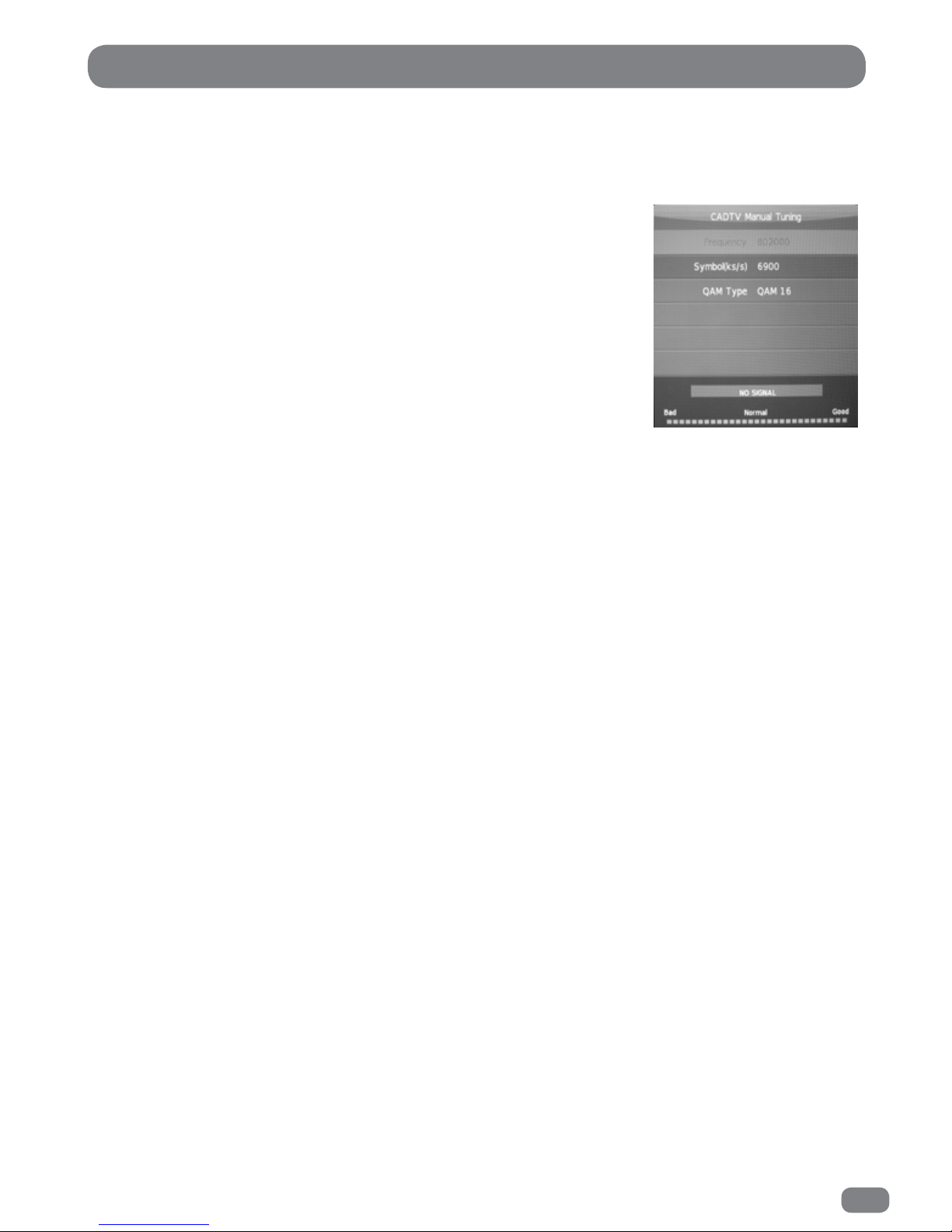
CADTV Manual Tuning
1 Press the MENU button to display the CHANNEL menu.
2 Press the
56
buttons to highlight the CADTV MANUAL TUNING.
3 Press the OK button to display the CADTV Manual Tuning menu.
4 Press the
56
buttons to highlight the item to be adjusted.
4a Set the required value of FREQUENCY by pressing the
34
buttons or entering the value using the number buttons
on the remote control.
4b Set the required value of SYMBOL(Ks/s) by pressing the
34
buttons or entering the value using the number buttons
on the remote control.
4c Set the required value of QAM TYPE by pressing the
34
buttons.
5 The CADTV Manual Tuning menu will show if a signal is being received on the selected
channel. A signal must be present in order to attempt to tune channels.
6 Press the OK button to begin search.
To tune additional stations repeat steps 4 to 6.
Page 34

32
A deleted programme can only be restored by retuning the TileVision® using Auto or
Manual Tuning. Setting SKIP for unwanted programmes is usually a better option.
Programme Edit allows programmes to be deleted, skipped or selected as favourites.
Deleted programmes are removed completely and are not available at all until the TileVision
®
is retuned using
Auto or Manual Tuning.
Skipped programmes are not available by pressing the
PR +
or the
PR –
buttons but they can be selected from
the EPG, the channel list or by entering a channel number directly.
Favourite programmes are included in the Favourite List which can be displayed by pressing the
FAV
button.
Programme Edit in DTV Mode
1 Select DTV input, refer to page 24
2
Press the MENU button to display the
CHANNEL
menu.
3
Press the 56 button to highlight Programme Edit
4
Press the OK button to display the Programme Edit menu.
5
Select a programme with the 56 buttons.
5a
To DELETE the programme completely and make it unavailable until the TileVision® is retuned, press
the RED button.
5b
To SKIP past the programme when using the
PR +
or
PR –
buttons, press the BLUE button. A SKIP
symbol will be appear next to the programme to indicate that it has been selected as skipped. To include a
skipped programme when selecting programmes via the
PR +
or
PR –
buttons, press the BLUE button, the
skip symbol will be removed.
5c
To include the programme in the FAVOURITES list, press the
FAV
button. A HEART will appear next to
the programme to indicate that it has been added to the favourites list. To remove a programme from the
favourites list press the
FAV
button, the heart will be removed from the programme.
6
Press the
MENU
button to close the Programme Edit dialogue.
Programme Edit DTV
Page 35

33
Programme Edit ATV / CTV (Cable TV)
A deleted programme can only be restored by retuning the TileVision® using Auto or
Manual Tuning. Setting SKIP for unwanted programmes is usually a better option.
Programme Edit allows programmes to be deleted, skipped or selected as favourites.
Deleted programmes are removed completely and are not available at all until the TileVision
®
is retuned using
Auto or Manual Tuning.
Skipped programmes are not available by pressing the
PR +
or the
PR –
buttons but they can be selected from
the channel list or by entering a channel number directly.
Favourite programmes are included in the Favourite List which can be displayed by pressing the
FAV
button.
Programme Edit in ATV Mode
1
Select ATV input, refer to page 24
2
Press the MENU button to display the
CHANNEL
menu.
3
Press the 56 button to highlight Programme Edit
4
Press the OK button to display the PROGRAMME EDIT menu.
5
Select a channel with the 56 buttons.
5a
To DELETE the programme completely and make it unavailable until the TileVision® is retuned, press
the RED button.
5b
To SKIP past the programme when using the
PR +
or
PR –
buttons, press the BLUE button. A SKIP
symbol will be appear next to the programme to indicate that it has been selected as skipped. To include a
skipped programme when selecting channels via the
PR +
or
PR –
buttons, press the BLUE button, the skip
symbol will be removed.
5c
To include the programme in the FAVOURITES list, press the
FAV
button. A HEART will appear next to
the programme to indicate that it has been added to the favourites list. To remove a programme from the
favourites list press the
FAV
button, the heart will be removed from the programme.
5d
To RENAME a programme press the GREEN button. Press the 56 buttons to select a character
(holding the 56 buttons pressed will perform a fast search of the available characters) and press the 34
buttons to select the position. A maximum of four characters can be used to name a programme. To save
the new name press the GREEN button.
5e
To MOVE a programme to a new position in the list. Press the YELLOW button. Press the 56
buttons to move the programme to the requires position. To save the programme in the new position press
the YELLOW button.
6
Press the
MENU
button to close the Programme Edit dialogue.
Page 36

34
Signal Information
Signal information is only available when DTV is being viewed. The information detailed is regarding the
multiplex currently being viewed.
1
Press the MENU button to display the
CHANNEL
menu.
2
Press the 56 buttons to HIGHLIGHT the S
IGNAL INFORMATION
menu.
3
Press the OK button to display the signal information.
4
Press the MENU button to return to the
CHANNEL
menu.
CI Information
If a Conditional Access Module (CAM) is installed CI information is available via the CHANNEL menu as follows:
Note: If a Conditional Access Module (CAM) is not installed the option CI Information will be greyed out and not
selectable.
1
Press the MENU button to display the
CHANNEL
menu.
2
Press the 56 buttons to HIGHLIGHT the CI INFORMATION menu.
3
Press the OK button to display the CI Information
With a CAM installed the message ‘Loading CI MMI...’ will be displayed whilst the TileVision® accesses the
information from the CAM and viewing card.
4
When the Main menu is displayed,
4a
Press the 56 buttons to select a menu option
4b
Press the OK button to view the available information.
4c
Press the OK or EXIT button to return to the main CI Information menu.
5
Press the EXIT button to close the menu.
LCN (Logical Channel Number) Sorting
1
Press the MENU button to display CHANNEL menu.
3
Press the
56
buttons to highlight LCN SORTING.
4
Press the OK button to toggle the setting between ON and OFF.
5
Press the MENU button to exit the CHANNEL menu.
Page 37

35
Changing Channels
There are five ways to change to a new channel on the TileVision®:
1
Enter the programme number directly by pressing the number keys. When choosing a programme from 1–9
there is no need to press the 0 key first.
2
Press the PR + or PR - buttons to switch from programme to programme in sequence.
3
Press the OK button to display the Channel List. When the list is displayed use the 56 buttons to select a
programme and press the OK button to switch to the selected programme.
The PR + or PR - buttons can be used to move up or down one page at a time.
The Channel List will continue to be displayed for a few seconds or until the EXIT button is pressed.
4
Press the FAV button to display the Favourite List. When the list is displayed use the 56 buttons to select a
programme and press the OK button to switch to the selected programme. To edit the Favourite Programme
list see pages 32 & 33.
The Favourite List will continue to be displayed for a few seconds or until the EXIT button is pressed.
5
When watching DTV press the EPG button to display the Electronic Programme Guide.
When the Programme Guide is displayed use the 56 buttons to select a programme and press the OK
button to select the chosen programme. Press the PAGE UP button to scroll up a page at a time and the
PAGE DOWN button to scroll down a page at a time.
Press the
EPG
or
EXIT
button to close the EPG.
Page 38
36
Basic DTV Programme Information
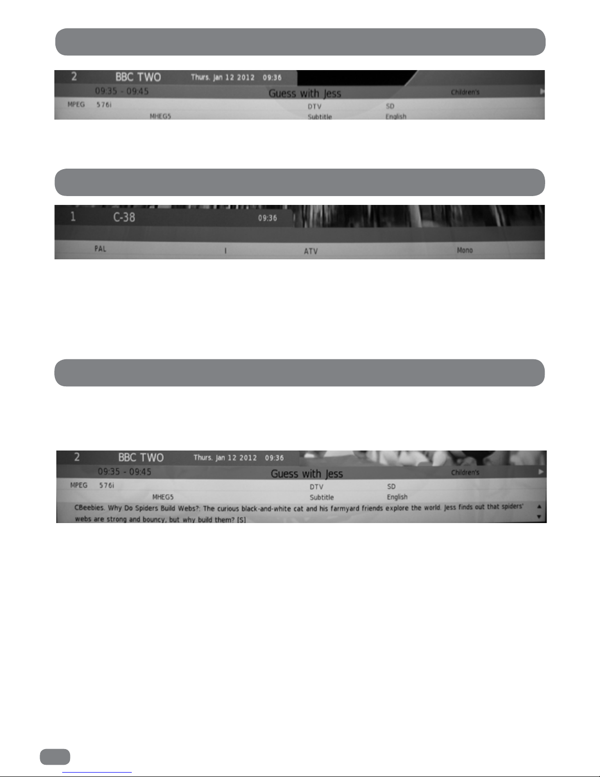
The channel number, channel name and signal information are always displayed on screen for a few seconds
whenever switching from one channel to another.
The channel number, channel name and signal information are always displayed on screen for a few seconds
whenever switching from one channel to another.
Because detailed information is not broadcast on analogue television, pressing the INFO
button will display the same information as is shown when changing channel.
More detailed information about the current programme can be seen at any time by pressing the INFO button.
Press the INFO button again to clear the information banner from the screen.
The information contained in the banner is as follows:
Line 1 the channel, the date and the current time.
Line 2 the start and end times of the programme and the programme title.
Line 3 the video mode (576i denotes standard resolution), the availability of MHEG digital text, the availability
of subtitles and the audio language.
Line 4 a brief synopsis of the program.
To view the information on the next programme press the 4 button.
Basic ATV Programme Information
Detailed DTV Programme Information
Page 39
37
Viewing the EPG
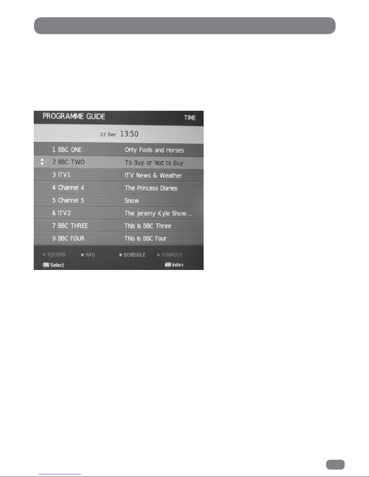
The EPG information is provided by the broadcasters.
Programme entries may appear blank or out of date as a result of the information broadcast on a given
channel. The display will dynamically update as soon as new information becomes available.
EPG information can be viewed at any time when watching digital programmes.
1
Press the
EPG
button to display the Electronic Programme Guide.
2
Use the 56 & 34 buttons to move the highlight around the EPG and use the Page Up and Page Down
buttons to move up or down one page at a time.
3
Press the OK button to select the currently highlighted channel.
4
Press the EPG or EXIT button to close the EPG.
Detailed programme information is available without closing the EPG by pressing the INFO button.
To return to the EPG press the INFO button again.
The Electronic Programme Guide (EPG)
Page 40

38
The EPG Timer Recording
The Electronic Programme Guide is only available when viewing Digital TV or Satellite TV.
A USB memory stick (flash drive) must be installed.
To record a program from the EPG.
1
Press the EPG button. The EPG will be displayed with the current channel being viewed, highlighted.
2
Press the 5 button to highlight the Date Time Bar (at the top of the EPG listing). For a fast scroll up the
EPG list press the Page Up button.
3
Press the 34 buttons to set the required date, the date can be set within the next seven days from the
current date.
4
Press the 5 button to highlight Programme Guide Time.
5
Press the 34 buttons to change the Programme Guide Time to Programme Guide Channel.
6
Press the 6 button to highlight Channel Select.
7
Press the 34 buttons to select the required channel.
8
Press the 56 buttons to highlight the required programme and time.
9
Press the RED button.
10
The RECORDER settings will be displayed.
11
Press the OK button.
12
The Timer Confirmed notification will be displayed.
If a programme recording time conflicts with another recording the Timer Confirmation notice will
advise a Timer Overlap and the current setting will be deleted. The timer recording will not be set.
Timer Recording - Indication.
With the TileVision in standby mode (red LED lit). The LED will change to green to indicate
that the recording is in progress, a picture will NOT be displayed. On completion of the
recording the LED will revert back to red.
Page 41

39
The EPG Timer Recording
The Electronic Programme Guide is only available when viewing Digital TV or Satellite TV.
To record a program from the EPG.
1
Press the EPG button. The EPG will be displayed with the current channel being viewed, highlighted.
2
Press the 5 button to highlight the Date Time Bar (at the top of the EPG listing). For a fast scroll up the
EPG list press the Page Up button.
3
Press the 34 button to set the required date, the date can be set within the next seven days from the
current date.
4
Press the 5 button to highlight Programme Guide Time.
5
Press the 34 buttons to change the Programme Guide Time to Programme Guide Channel.
6
Press the 6 button to highlight Channel Select.
7
Press the 34 buttons to select the required channel.
8
Press the 56 buttons to highlight the required programme and time.
9
Press the RED button.
10
The RECORDER settings will be displayed.
11
Press the 56 buttons to highlight MODE.
11a Press the 34 buttons to set the required recording sequence.
ONCE.
EVERYDAY.
WEEKLY.
12
When the mode is not set to auto, the START time and END time can be adjusted.
12a Press the 56 buttons to highlight the item to be adjusted.
12b Press the 34 buttons to set the value.
13
When all the information has been entered press the OK button.
14
The Timer Confirmed notification will be displayed.
If a programme recording time conflicts with another recording the Timer Confirmation notice will
advise a Timer Overlap and the current setting will be deleted. The timer recording will not be set.
Timer Recording - Indication.
With the TileVision in standby mode (red LED lit). The LED will change to green to indicate
that the recording is in progress, a picture will NOT be displayed. On completion of the
recording the LED will revert back to red.
Manual adjustment of a timer recording.
Page 42
40
The Timer Recording Schedule
The Schedule List can be displayed for checking or deleting a program that is set to be recorded, or a reminder
of a program.
1
Press the EPG button to display the EPG.
2
Press the YELLOW button (Schedule). A list of programs that is scheduled to be recorded will be shown.
2a
To delete a program press the 56 buttons to highlight the programme to be deleted. Press the
RED button to delete the scheduled recording or reminder. On pressing the RED button the schedule
list will close and normal TV viewing will be restored.
3
Press the EXIT button to return to normal TV viewing.
3a
Press the YELLOW button to return to the EPG.
A MOVIE symbol indicates that the program is set to record.
A TIMER symbol indicates that the program is set as a reminder.
Time Shift - Recording
A USB memory stick (flash drive) must be installed.
The viewing of a current program can be paused temporarily, and then played back.
Press the TIMESHIFT button.
A pause indicator will appear at the top left of the picture.
To playback the paused program press the PLAY button.
To display or remove the control bar press the REC / HOME button.
To pause playback press the TIMESHIFT button.
To exit the timeshift mode and return to normal viewing, press the EXIT button.
Page 43

41
Program Reminder
A USB memory stick (flash drive) must be installed.
To quickly record the current program for viewing at a later time.
Press the RECORD button.
The recording of the program starts immediately. The record indicator will appear at the top left of the
picture.
To display or remove the control bar press the RECORD button.
To stop the recording, press the STOP button.
Recording The Current Program
The Schedule List can be displayed for checking or deleting a reminder that has been set for a program.
1
Press the EPG button to display the EPG.
2
Select the program for which a reminder is to be set.
3
Press the BLUE button to display the REMINDER menu.
3a Use the 34 & 56 buttons to alter the channel, time and frequency of the
reminder, if required.
4 When the reminder timings are correct, press the OK button to store the reminder.
Page 44

42
The PVR (Personal Video Recorder) List
1
Press the PVR LIST button. The PVR list will be displayed.
2
Press the 56 buttons to highlight the required recording.
3
Press the OK button or PLAY button to start the playback of the recording.
Digital Media Player
A USB memory stick (flash drive) must be installed.
1
Select the source input as Digital Media Player, see page 24.
2
Press the 34 buttons to highlight the media, Photo, Music, Movie or Text.
3
Press the OK button.
3a
If more than one USB memory stick is installed, press the 34 button to highlight were the
content is stored.
4
Press the OK button to select the USB memory stick.
5
Press the 3456 buttons to select the required item.
6
Press the OK button
6a
Repeat the sequence 5 and 6 until the required content is displayed.
Pressing the OK button will display the item in a reduced size in the centre of the screen. Pressing
the PLAY button will give a full screen mode.
If the OK button is pressed during full screen play back the play back control bar is displayed.
The play back control bar will clear in a few seconds.
Page 45
43
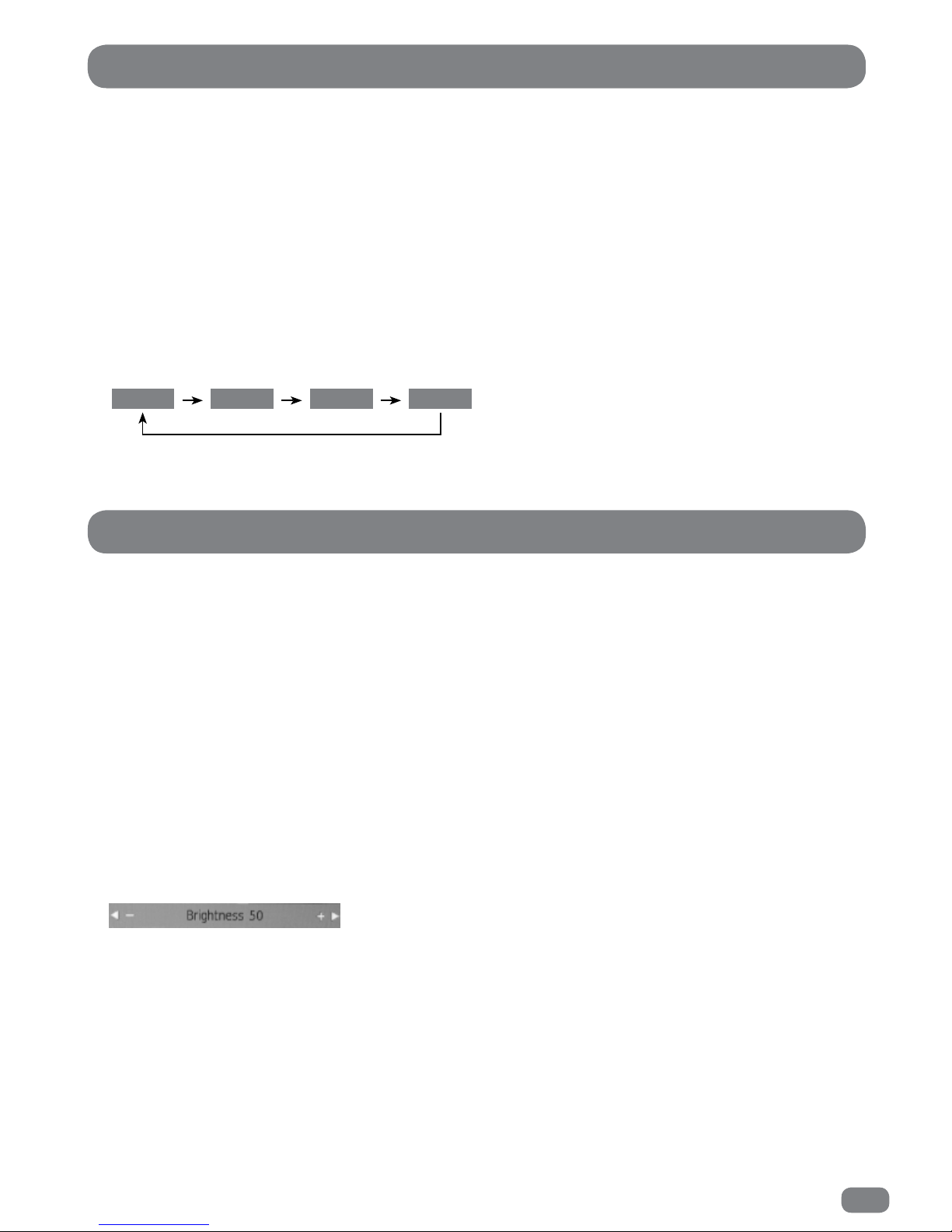
The Picture Mode setting is independently adjustable for each input. For example, DTV can be set to
Personal and the HDMI input can be set to Movie for DVD playback.
Setting the Picture Mode
Three preset picture modes can be selected or, using the User option, the Contrast, Brightness, Colour Intensity
and Sharpness can be set to preferred levels.
1
Press the MENU button.
2
Press the 34 buttons to select the PICTURE menu.
3
Press the OK button to display the Picture Mode Menu.
4
Press the 34 buttons to select any of the different modes as shown below.
5
Press the MENU button to close the Picture Mode menu.
Picture Settings
Standard Mild User Dynamic
Contrast, Brightness, Colour and Sharpness can only be adjusted in Personal Picture Mode.
Adjustments can be made as follows:
1
Press the MENU button.
2
Press the 34 button to select the PICTURE menu.
3
Press the OK button to display the Picture Mode Menu.
4
Press the 34 buttons to select User in the Picture Mode menu.
5
Press the 56 buttons to select, Contrast, Brightness, Colour or Sharpness.
6
Press the 34 buttons to adjust the value.
Adjustments are made with the PICTURE menu hidden so that most of the picture is visible. Only the item being
adjusted is shown on the screen.
7
When all the settings are as required press the OK button to return to the Picture Mode menu.
The Tint adjustment does not apply to TileVision®.
Picture Settings User Mode
Page 46
44
Picture Colour Temperature
The Colour Temperature can be set independently for each input. For example, DTV can be set to
Normal and the HDMI input can be set to Personal for DVD playback.
Setting the Colour Temperature
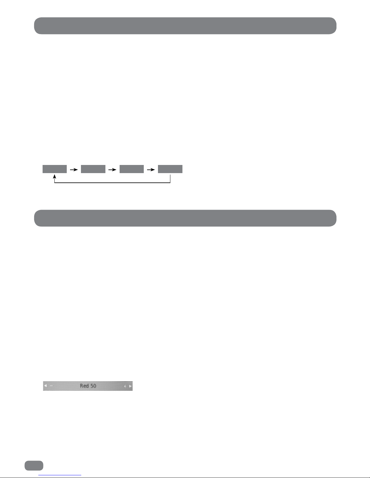
Three preset colour temperature settings can be selected or, using the User Colour Temperature mode, the mix
of Red, Green and Blue can be set to preferred levels.
1
Press the MENU button.
2
Press the 34 buttons to select the PICTURE menu.
3
Press the 56 buttons to highlight
Colour Temperature
.
4
Press the OK button to display Colour Temperature menu.
5
Press the 34 buttons to select any of the four settings as shown below.
6
Press the MENU button to close the Picture Mode menu.
Medium Warm User Cool
Colour Temperature User Mode
The levels of Red, Green and Blue can only be adjusted when using User Colour Temperature Mode.
Adjustments can be made as follows:
1
Press the MENU button.
2
Press the 34 buttons to select the PICTURE menu.
3
Press the 56 buttons to highlight
Colour Temperature
.
4
Press the OK button to display Colour Temperature menu.
5
Press the 34 buttons to select User in the Colour Temperature menu.
6
Press the 56 buttons to select, Red, Green or blue.
7
Press the 34 buttons to adjust the value.
Adjustments are made with the PICTURE menu hidden so that most of the picture is visible. Only the item
being adjusted is shown on the screen.
8
When all the settings are as required press the OK button to return to the Colour Temperature menu.
Picture Colour Temperature User Mode
Page 47
45
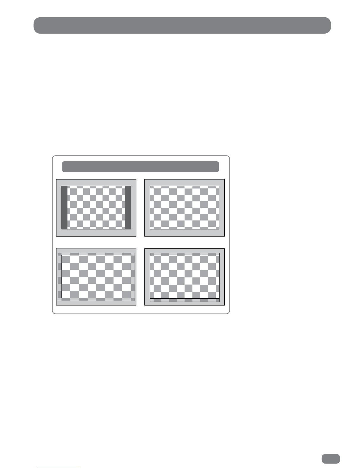
The Aspect Ratio can be independently set for each input. For example, DTV can be set to Auto and
the HDMI input can be set to Zoom1 for DVD playback.
If the Aspect Ratio is set to Auto, the TileVision
®
will alter the picture to best suit the programme being
received and there will be little need to change the setting manually.
1
Press the MENU button.
2
Press the 34 buttons to select the PICTURE menu.
3
Press the 56 buttons to highlight Aspect Ratio.
4
Press the OK button to display the Aspect Ratio Menu.
5
Press the 56 buttons to select any of the different settings as shown below.
6
Press the MENU button to close the Aspect Ratio menu.
Picture Aspect Ratio
How aspect ratio settings alter the picture
Zoom 2Zoom 1
4:3 16:9
Page 48
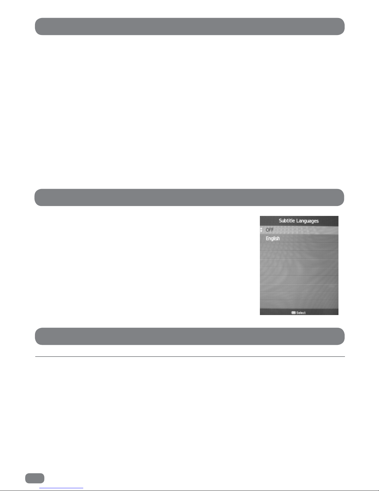
46
Noise Reduction can be independently set for each input except PC RGB where Noise Reduction
setting is not required.
If noise reduction is needed, Default is the recommended setting.
Noise reduction can be set as follows:
1
Press the MENU button.
2
Press the 34 buttons to select the PICTURE menu.
3
Press the 56 buttons to highlight
Noise Reduction.
4
Press the OK button to display Noise Reduction menu.
5
Press the 56 buttons to select the required settings.
Off, Low, Middle, High or Default.
6
Press the Menu button to close the Noise Reduction menu.
Subtitles
Most DTV broadcasts include subtitles in at least one language. To select
subtitles or turn subtitles off press the SUBTITLES button and the
Subtitle
Languages
list will be displayed.
Press the 56 buttons to select a language or turn Subtitles off and press the
OK button to save settings and close the list.
Picture Noise Reduction
Sound Mute
The sound can be muted by pressing the
MUTE
button.
The mute flag will be displayed on the screen whenever the sound is muted.
To restore the sound to the previous level press the
MUTE
button or press either VOLUME button up or
down.
Subtitles
Sound - Mute
Page 49
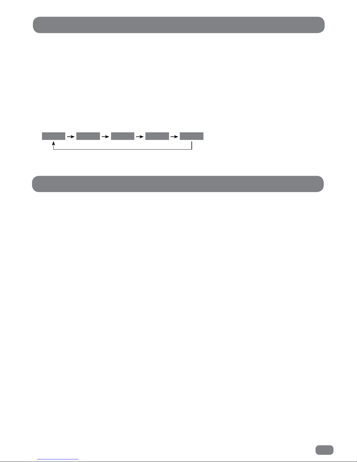
47
Four preset sound modes can be selected or, using the User mode, five frequency bands can be set
to preferred levels.
Setting the Sound Mode
1
Press the MENU button.
2
Press the 34 buttons to select the SOUND menu.
3
Press the OK button to display the Sound Mode menu.
4
Press the 34 buttons to select any of the different modes as shown below.
5
Press the MENU button to save the settings and close the Sound Mode menu.
Sound Settings
Standard UserSportsMovieMusic
Five frequency bands can be adjusted by cutting or boosting the selected frequency. Adjustments can be made
as follows:
1
Press the MENU button.
2
Press the 34 buttons to select the SOUND menu.
3
Press the OK button to display the Sound Mode menu.
4
Press the 34 buttons to select User in the Sound Mode menu.
5
Press the 56 buttons to select a frequency band.
6
Press the 34 buttons to adjust the value.
7
When all the settings are as required press the MENU button to save the settings and close the adjustment
dialogue.
Sound - User Mode
Page 50

48
Surround sound will enhance the audio and provide a more enjoyable and involving presentation.
1
Press the MENU button.
2
Press the 34 buttons to select the SOUND menu.
3
Press the 56 buttons to highlight Surround Sound.
4
Press the OK button to display the Surround Sound menu.
5
Press the 56 buttons to select the required Surround Sound option. OFF, Surround or SRS TruSurround XT.
6
Press the MENU to save the setting and close the Surround Sound menu.
Surround Sound
1
Press the MENU button.
2
Press the 34 buttons to select the SOUND menu.
3
Press the 56 buttons to highlight Balance.
4
Press the OK button to display the Balance Adjustment menu.
5
Press the 34 buttons to adjust the Left/Right balance.
6
Press the MENU to save the setting and close the Balance Adjustment menu.
If there is an large difference between the volume of one programme and another, setting
Auto Volume
to on
will reduce the disparity.
1
Press the MENU button.
2
Press the 34 buttons to select the SOUND menu.
3
Press the 56 buttons to highlight Auto Volume.
4
Press the OK button to switch between On and Off.
5
Press the MENU button to save the setting and close the SOUND menu.
Adjusting The Balance
Auto Volume
Page 51
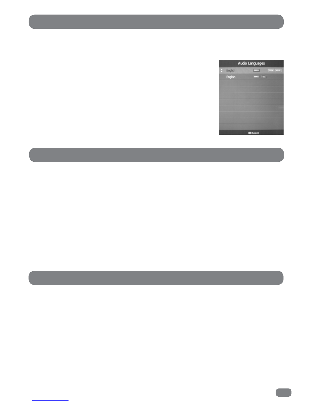
49
Some DTV broadcasts can include multiple audio languages and/or narrative audio descriptions for the visually
impaired (V.I.). The Audio Languages menu allows available languages to be selected and broadcasts with
audio descriptions to be chosen if required.
DTV Audio Languages
1
Press the MENU button.
2
Press the 34 buttons to select the SOUND menu.
3
Press the 56 buttons to highlight AD Switch.
4
Press the OK button to display the AD Switch menu.
5
Press the 34 buttons to set the AD (audio description) to ON or OFF. With the AD set to off the volume
control is greyed out. For adjustment of the volume level AD must be set to ON.
6
Press the 56 buttons to highlight AD Volume.
7
Press the 34 buttons to set the AD volume to the require level.
8
Press the MENU button to exit the AD Switch menu.
1
Press the MENU button.
2
Press the 34 buttons to select the SOUND menu.
3
Press the 56 buttons to highlight SPDIF Mode.
4
Press the OK button to toggle the setting between AUTO and PCM mode.
5
Press the MENU button to exit the SOUND menu.
In
DTV
mode the sound output for the left and right speakers can be selected as
follows:
1
Press the
AUDIO
button to open the
Audio Languages
list.
2
Press the 56 buttons to select the required broadcast language and V.I.
option.
3
Press the 3 or 4 buttons to sequence through the three options;
L+R, L+L
, or
R+R
.
4
Press the OK button to save settings and close the list.
AD Switch
SPDIF Mode
Page 52

50
1
Press the MENU button.
2
Press the 34 buttons to select the TIME menu.
3
Press the 56 buttons to highlight OFF TIME.
4
Press the OK button to display the OFF TIME menu.
5
Press the 34 buttons to set the OFF TIME to the required setting (Off, Once, Every Day, Mon~Fri, Mon~Sat,
Sat~Sun, Sunday). With the OFF TIME set to off the time settings are greyed out.
6
Press the 56 buttons to highlight HOUR.
7
Press the 34 buttons to set the HOUR to the required setting.
6
Press the 56 buttons to highlight MINUTES.
7
Press the 34 buttons to set the MINUTES to the required setting.
8
Press the MENU button to exit the OFF TIME menu.
Setting The OFF Time
The time menu allows the TileVision® to be programmed to switch on or off at preset times. Options available
are Off, Once, Every Day, Mon~Fri, Mon~Sat, Sat~Sun, Sunday.
Page 53

51
Setting The ON Time
The time menu allows the TileVision® to be programmed to switch on or off at preset times. Options available
are Off, Once, Every Day, Mon~Fri, Mon~Sat, Sat~Sun, Sunday.
1
Press the MENU button.
2
Press the 34 buttons to select the TIME menu.
3
Press the 56 buttons to highlight ON TIME.
4
Press the OK button to display the ON TIME menu.
5
Press the 34 buttons to set the ON TIME to the required setting (Off, Once, Every Day, Mon~Fri, Mon~Sat,
Sat~Sun, Sunday). With the ON TIME set to off the time settings are greyed out.
6
Press the 56 buttons to highlight HOUR.
7
Press the 34 buttons to set the HOUR to the required setting.
6
Press the 56 buttons to highlight MINUTES.
7
Press the 34 buttons to set the MINUTES to the required setting.
6
Press the 56 buttons to highlight the input.
7
Press the 34 buttons to set the input to the required setting (DTV, ATV, Radio, SCART, Component,PC-RGB,
HDMI 1, HDMI 2, AV, Digital Media Player, Satellite).
7a
With the input DTV, ATV, Radio or Satellite selected, the channel can be selected. Press the 56
buttons to highlight the channel.
7b
Press the 34 buttons to select the required channel.
6
Press the 56 buttons to highlight VOLUME.
7
Press the 34 buttons to set the VOLUME to the required setting.
8
Press the MENU button to exit the ON TIME menu.
Page 54

52
Sleep Timer
The TileVision® incorporates a sleep timer which can be set to turn the unit off after a preset time. The
available delay times are:
10, 20, 30, 60, 90, 120, 180, and 240 minutes.
The sleep time can be set as follows:
1
Press the MENU button.
2
Press the 34 buttons to display the TIME menu.
3
Press the 56 buttons to highlight the SLEEP TIMER menu.
4
Press the OK button to display the SLEEP TIMER menu.
5
Press the 56 buttons to select the required delay.
6
Press the MENU button to close the SLEEP TIMER menu.
An on-screen countdown will be displayed from 30 seconds before the TileVision® switches off.
The TileVision
®
incorporates a auto standby function. If there has been no operation of the TileVision® after a
set time the TileVision® will switch to standby. Time lengths available, OFF, 3 hours, 4 hours or 5 hours.
1
Press the MENU button.
2
Press the 34 buttons to display the TIME menu.
3
Press the 56 buttons to HIGHLIGHT the AUTO STANDBY menu.
4
Press the OK button to display the AUTO STANDBY menu.
5
Press the 56 buttons to select the required delay., OFF, 3 hours, 4 hours or 5 hours.
6
Press the MENU button to close the AUTO STANDBY menu.
An on-screen countdown will be displayed from 30 seconds before the TileVision® switches off.
Auto Standby
The Sleep Timer can be changed whilst watching a
programme. Press the Sleep button to sequence
through the delay settings.
Page 55

53
Setting The Time Zone
There is a choice of 44 cities in various time zones.
1
Press the MENU button.
2
Press the 34 buttons to display the TIME menu.
3
Press the 56 button to highlight TIME ZONE.
4
Press the OK button to display the TIME ZONE selection menu.
3
Press the 56
and
34 buttons until the required
City / Time Zone
is selected.
4
Press the MENU button to close the TIME Zone menu.
1
Press the MENU button.
2
Press the 34 buttons to select the TIME menu.
3
Press the 56 buttons to highlight DAYLIGHT SAVING.
4
Press the OK button to toggle the setting between ON and OFF.
5
Press the MENU button to exit the TIME menu.
Daylight Saving
Page 56

54
On Screen Display Language
The on-screen menus and lists can be in any of the following twenty two languages: Český, Dansk, Deutsch,
English, Español, Ελληνικά, Français, Hrvatski, Italiano, Magyar, Nederlands, Norsk, Polski, Portugês,
Pyccкий, Româneste, Slovenščina, Srpski, Suomi, Svenska, Български, Slovak.
1
Press the MENU button.
2
Press the 34 buttons to display the OPTION menu.
3
Press the 56 button to highlight OSD LANGUAGE.
4
Press the OK button to display the OSD LANGUAGE selection menu.
3
Press the 56
and
34 buttons until the required
language
is selected.
4
Press the MENU button to close the OSD LANGUAGE menu.
All the on-screen displays will now be in the chosen language.
The primary or secondary language are used as appropriate if they are available when a multiple language
source is broadcast.
Set the preferred audio languages as follows:
1
Press the MENU button.
2
Press the 34 buttons to display the OPTION menu.
3
Press the 56 buttons twice to HIGHLIGHT the AUDIO LANGUAGES menu.
4
Press the OK button to display the AUDIO LANGUAGES selection menu.
5
Press the 34 buttons to display PRIMARY or SECONDARY.
6
Press the 6 button to move to the language selection area.
7
Press the 56 and 34 buttons to select the required language.
8
Press the
MENU
button to return to the AUDIO LANGUAGES (top) selection menu.
8a
Repeat from instruction 5 to set a SECONDARY language.
9
Press the
MENU
button to exit the AUDIO LANGUAGES selection menu.
Audio Language
Page 57

55
Subtitle Language
The primary or secondary language are used as appropriate if they are available when multiple subtitle
languages are broadcast.
Set the preferred subtitle languages as follows:
1
Press the MENU button.
2
Press the 34 buttons to display the OPTION menu.
3
Press the 56 buttons to HIGHLIGHT the SUBTITLE LANGUAGES menu.
4
Press the OK button to display the SUBTITLE LANGUAGES selection menu.
5
Press the 34 buttons to display PRIMARY or SECONDARY.
6
Press the 6 button to move to the language selection area.
7
Press the 56 and 34 buttons to select the required language.
8
Press the
MENU
button to return to the SUBTITLE LANGUAGES (top) selection menu.
8a
Repeat from instruction 5 to set a SECONDARY language.
9
Press the
MENU
button to close the SUBTITLE LANGUAGES selection menu.
If a broadcast includes alternative audio for the hard of hearing it will be selected when Hearing Impaired is set
to on.
1
Press the MENU button.
2
Press the 34 buttons to select the OPTION menu.
3
Press the 56 buttons to highlight HEARING IMPAIRED.
4
Press the OK button to toggle the setting between ON and OFF.
5
Press the MENU button to exit the OPTION menu.
Hearing Impaired
Page 58

56
PVR File System
The PVR USB memory stick performance can be checked or if required the PVR USB memory stick can be
formatted.
1
Press the MENU button.
2
Press the
34
buttons to display the OPTION menu.
3
Press the
56
buttons to highlight the PVR File System option.
4
Press the OK button to display the PVR File System menu.
5
If two USB memory sticks are connected, press the
34
buttons to select the required USB memory stick.
6
Press the
56
buttons to highlight the required option.
6a To check PVR File System. Press the OK button. After testing is complete, information
regarding the performance of the USB memory stick is displayed.
6b To FORMAT the USB memory stick. Press the OK button.
6c
Press the
34
buttons to select the format system type.
FAT32 the maximum capacity of the USB memory stick will be used for the PVR file.
Fast Format: The recording capacity for the PVR file can be set. Press the
56
buttons to select the recording capacity. Press the
34
buttons to set the value of
the recording capacity.
6d
Press the OK button when the formatting options have been set.
6e
Press the 3 button to START formatting, press the 4 button to exit without formatting.
ECO Mode
1
Press the MENU button.
2
Press the 34 buttons to display the OPTION menu.
3
Press the 56 buttons (scroll to the second page) to HIGHLIGHT the ECO MODE menu.
4
Press the OK button to display the ECO MODE menu.
5
Press the 56 buttons to select the required setting, LOW, MIDDLE or HIGH.
6
Press the MENU button to close the ECO MODE menu.
Page 59

57
Restore Default
There is normally no need to restore factory settings. It can however, be useful to restore factory settings as an
easy way of clearing such restrictions as blocked, skipped channels and personal settings, etc.
The default factory settings can be restored as follows:
1
Press the MENU button.
2
Press the 34 buttons to display the OPTION menu.
3
Press the 56 buttons to highlight the RESTORE DEFAULT option.
4
Press the OK button to display the WARNING menu.
5
Press the 3 button to select YES and restore all setting.
5a
Press the 4 button to select NO and return to the OPTION menu.
Restore default does not:
Restore the password to the original default code of 0000.
Set the LOCK to off.
Remove the age restriction set with parental guidance.
1
Press the MENU button.
2
Press the 34 buttons to display the OPTION menu.
3
Press the 56 buttons to highlight the OSD TIME menu.
4
Press the OK button to display the OSD TIME menu.
5
Press the 56 buttons to select the required delay, 15 seconds, 30 seconds or 60 seconds.
6
Press the MENU button to close the OSD TIME menu.
OSD (On Screen Display) Time
Page 60

58
Lock System
The lock menu allows a password to be entered so that a number of key settings can be locked,
selected programmes can be blocked and parental controls can be imposed.
When lock system is on, Auto Tuning, DTV Manual Tuning and ATV Manual Tuning can not be accessed from the
CHANNEL menu without entering the password. All other menu options are not affected.
The TileVision
®
default four digit password is 0000.
Before adjustment of the settings on the Lock Menu can be undertaken, the Lock Menu screen must
be UNLOCKED first by entering the password.
To UNLOCK the Lock Menu screen.
1
Press the MENU button.
2
Press the 34 buttons to display the LOCK menu.
3
Press the 56 buttons to highlight the LOCK SYSTEM option.
4
Press the OK button to display the ENTER PASSWORD dialogue.
5
Enter the correct four digit code using the number pad on the remote control.
With the correct code entered the display will return to the LOCK menu.
1
UNLOCK the LOCK MENU screen, see above.
2
Press the OK button to switch the setting between ON or OFF.
3
Press the
MENU
button to exit the LOCK menu.
To Set The Lock System ON or OFF
Parental Guidance
The parental guidance option allows any age from 4 to 18 to be select for all programmes. Parental guidance is
set as follows:
1
UNLOCK the LOCK MENU screen, see above.
2
Press the 56 buttons to highlight the PARENTAL GUIDANCE menu.
3
Press the OK button to display the PARENTAL GUIDANCE menu.
4
Press the 56 buttons to select the required age restriction.
5
Press the
MENU
button to return from the PARENTAL GUIDANCE menu.
Page 61

59
Change Password
1
Press the MENU button.
2
Press the 34 buttons to display the LOCK menu.
3
Press the 56 buttons to highlight the SET PASSWORD option.
4
Press the OK button to open the password window.
5
Enter the current four digit code using the number pad on the remote control.
6
Enter the NEW four digit code using the number pad on the remote control.
7
Reenter the NEW four digit code using the number pad on the remote control.
When completed the display will return to the LOCK menu.
If the default password of 0000 is replaced by a user password and the password
is then forgotten, contact the place of purchase to obtain the master password.
Blocked programmes can only be viewed by entering the password. The programmes are selected in the
normal way but it is necessary to enter the password before the programme is shown.
Programmes are blocked as follows:
1
UNLOCK the LOCK MENU screen, see page 58.
2
Press the 56 buttons to highlight the BLOCK PROGRAM menu.
3
Press the OK button to display a list of all the programs
4
Press the 56 buttons to select
the required Programme
.
5
Press the GREEN button to BLOCK the selected programme. A padlock symbol will appear next to the
blocked programme.
5a
To UNBLOCK a blocked programme press the GREEN button.
4
Press the
MENU
button to return from the BLOCK PROGRAMME menu.
Block Programme
Page 62
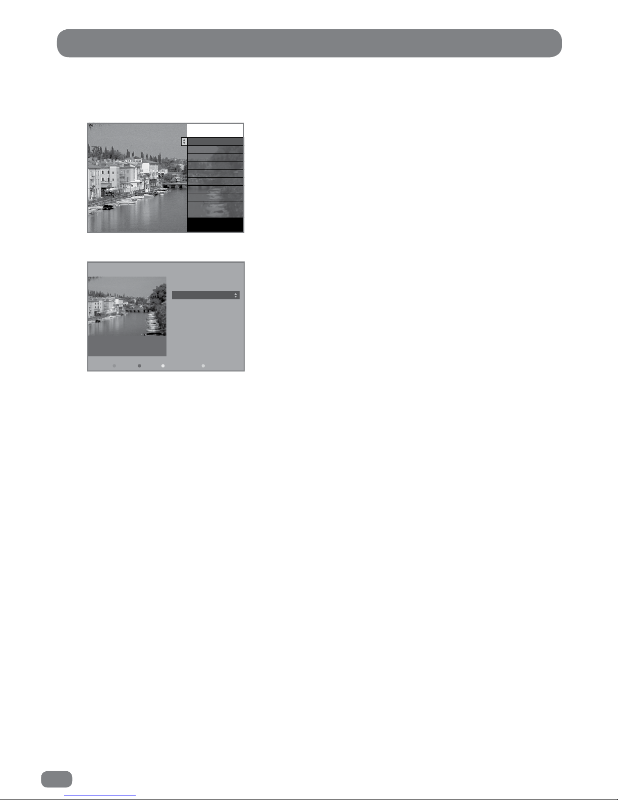
60
DTV Text
To access DTV Text press the TEXT or RED button depending on the programme’s broadcaster. A small
banner 'loading…' will be displayed on screen. After a few seconds the broadcaster’s menu will appear,
either overlaying part of the current programme:
or with the current programme in a smaller window next to the text menus and instructions:
Use the
56
buttons (or in some cases the
34
buttons) to navigate the menus and the OK button to
select items. Use the RED, GREEN, YELLOW and BLUE buttons to access shortcuts, help and additional
menus etc., as shown on screen.
To exit DTV Text press the TEXT, the EXIT button or change channel.
All DTV Text navigation uses the
5634,
Colour and 0–9 number buttons, all functions are available
with the TileVision® splashproof remote control.
Channel Logo
Item one
Item two
Item three
Item four
Item five
Item six
Item seve n
INDEX
Latest news item:
To exit, press TEXT
Typical
overlay
example
Channel Logo
Item one 300
Item two 150
Item three 200
Item fo ur 170
Item five 110
Item six 800
Item seven 160
Item eight 850
Item nine 121
Latest news item:
Home
MENUSHORTCUTSHELPHOME
adveretising banner
Typical
inset
example
Some broadcasters show a red on-screen prompt
when DTV Text is available.
To remove the prompt from the screen press the
Green button.
DTV Text is not available immediately after
changing channel as it takes a few seconds for
the TileVision® to receive the data from the
broadcaster.
Page 63
61
ATV Teletext
A
B C D
F
E
Functions of Teletext
Part Display Contents
A Selected page number.
B Broadcast Station identity.
C Current page number or searching status.
D Date and time.
E Text information.
F FastText information.
Red, Green, Yellow, Blue
Switching Teletext On
1
Press the TEXT button once to view the Teletext pages.
2 Use the 0-9 number buttons and the RED, GREEN, YELLOW and BLUE FastText buttons to
navigate the text pages.
3 Press the TEXT button again to switch to mix mode with the text overlaying the TV picture.
Press the TEXT button again to switch Teletext off and return to normal viewing.
Page 64

62
Press and release the device button: TileVision® (TV), satellite receiver (SAT) or DVD recorder/player (DVD) that
you wish to control. Press the function button you require. The LEDs will light to confirm that a signal is being
sent and which device is being controlled.
To select a different device to control, press and release the device button: TileVision® (TV) satellite receiver
(SAT) or DVD recorder/player (DVD) that you wish to control. Press the function button you require. The LEDs
will light to confirm that a signal is being sent and which device is being controlled.
TileVision® Codes
The TileVision® learning remote control is supplied with the TV device button set to the TileVision® TV22/FR1
and TV26/FR2 model remote control codes. If these remote control codes are accidentally erased, the three
digit code for the TileVision® is 368.
The remote control is preprogrammed with a library of codes covering all major device brands.
The full code lists for satellite receivers, DVD recorders/players and VCRs are available for
download from the TileVision® website www.tilevision.tv.
1
Locate the three digit code in the brand list, for the satellite receiver or DVD recorder/player that you wish
to control.
2
Press and hold down the Television (TV), satellite (SAT) or DVD recorder/player (DVD) device button until
the red light stays on.
3
Enter the three digit code using the number buttons 0–9.
4
As each digit is entered the red light will flash once and then remain on.
5
If the three digit code is correct the red light will go out. If the three digit code is incorrect the red light will
flash twice and then remain on.
6
Press the original device button again to exit the code entry mode.
Note: If a three digit code is not entered within 15 seconds the red light will flash twice and exit code entry
mode. Entering a three digit code will delete/erase the programmed buttons for that device.
Remote Control - How to Control a Device
Entering a Brand Code
Page 65

63
1
Switch the chosen device (TV, satellite receiver, DVD recorder/player) that you wish to find the code for, to
ON. When the correct code has been found the device will switch OFF.
2
Press and hold down the TV (TV), satellite (SAT) or DVD recorder/player (DVD) button until the red light
stays on, then release the button.
3
Press the power button once and release, this will start the auto search mode.
4
When the device switches OFF. Immediately press and release the device button that was initially selected
to save the code in the remote control.
When the red light switches off, all the codes have been tried and the auto search mode has been exited.
To exit the auto search mode before all the codes have been tried, press and release the device button that
was initially selected.
To learn which three digit code has been set to control the device see Checking/Recalling the Device Code
on page 64.
Auto Search – All Brand Codes
1
Switch the chosen device (TV, satellite receiver, DVD recorder/player) that you wish to find th
e cod
e for, to
ON. When the correct code has been found the device will switch OFF.
2
Press and hold down the TV (TV), satellite (SAT) or DVD recorder/player (DVD) button until the red light
stays on, then release the button.
3
Press PR+ or PR- once and release. Each time PR+ or PR- is pressed a code is transmitted.
To perform a fast search, press and hold down PR+ or PR- button.
When the device switches
OFF
, release the PR+ or PR- button.
Step 4 must be executed so that the code is saved in the remote control.
4
Press and release the device button that was initially selected to save the code in the remote control.
To learn which three digit code has been set to control the device see Checking/Recalling the Device Code
on page 64.
Manual Search - All Brand Codes
Page 66

64
To find out which three digit code is controlling any device:
1
Press and release the device button: TV (TV), satellite (SAT) or DVD recorder/player (DVD) for which you
want to find the code.
2
Press the same device button again, together with the OK button and release both buttons.
3
The red light will flash.
4
Count the number of flashes for each digit in the three digit code.
5
The red light will remain off for a short time between numbers.
6
When all three numbers have been flashed the red light will remain off.
One Flash = 1
Two Flashes = 2
Three Flashes = 3
Four Flashes = 4
Five Flashes = 5
Six Flashes = 6
Seven Flashes = 7
Eight Flashes = 8
Nine Flashes = 9
Ten Flashes = 0
For example:
Press and release the DVD recorder/player (DVD) button.
Press and release the DVD recorder/player (DVD) and OK buttons.
The remote control would then show nine flashes (9), pause, two flashes (2), pause, and one flash (1), to
confirm the three digit code of 921.
Checking/Recalling a Device Code
Page 67

65
High levels of ambient light such as natural sunlight or energy efficient fluorescent lights should be avoided
when manually programming the remote control.
Any button other than the device buttons TV, SAT and DVD and the SET button can be manually programmed.
1
Place the original remote control and the learning remote control roughly 10 mm apart facing ‘head-to-head’
with each other.
2
On the learning remote control press and release the required device button, TV (TV), satellite (SAT) or DVD
recorder/player (DVD) as appropriate.
3
Press and hold the SET button on the learning remote control until the red light lights and remains lit. The
remote control is now in learning mode.
If the red light does not turn on, go back to step 2 and try again.
4
On the learning remote control press and release the button that is to be programmed. The red light will
flash rapidly.
5
On the original remote control, press and hold the button that is to be learned. When the red light on the
learning remote control flashes three times and then remains lit the code has been learnt. If the
red light does not flash, repeat steps 4 and 5.
Note: If step 5 is not completed within 15 seconds the learning remote control will exit learning mode and
the light will stop flashing.
6
Repeat steps 4 and 5 to program other buttons.
7
Once the required buttons have been programmed press the SET button again on the learning remote
control to exit learning mode.
Manually Programming a Button
Deleting Programmed Buttons
1
Press and release the appropriate device button TV (TV), satellite (SAT) or
DVD recorder/player (DVD) to select which device’s programs are to be deleted.
2
Press and hold the chosen device button together with SET button until the red light flashes three times.
3
All of the programmed buttons for the chosen device have now been cleared of their programming.
Deleting programs from buttons does not delete any four digit brand code which has been entered.
Page 68
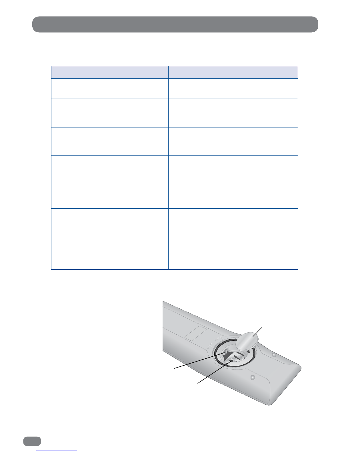
66
Problem Solution
The red light does not ash when
any button is pressed.
Replace the battery with a new type
CR2032 battery.
The red light does not ash when a
‘programmed’ button is pressed.
The button has not been programmed
or has not been programmed correctly.
Program the button.
The red light ashes when a button
is pressed but the TileVision® or
device does not respond.
Ensure that the remote control is within
three meters of, and pointed at, the
TileVision® or piece of equipment.
The remote control does not
operate a device correctly or some
commands are not working.
Try all listed codes for the device as
shown in the control code pdfs which
are available from the support section
of the TileVision® website or program
the buttons from the device’s own
remote control.
During learning the red light does
not ash three times or stays on
for a long time after pressing a
button to be learnt.
Memory is full or a bad capture has
occurred. For optimum learning, avoid
high levels of ambient light such as
natural sunlight or energy ecient
uorescent lights. Try adjusting the
position of the remote controls before
performing the procedure again.
Remote Control - Troubleshooting
Li Thi um Cel l
CR 203 2
3V
Li Thi um Cel l
CR 203 2
3V
A
B
C
If the remote control fails to operate after
the battery has been installed or
replaced.
A. Gently pull forward the small battery
terminal.
B. Gently raise up both prongs.
C. Insert the battery at an angle, so it
rests on the battery terminal A.
Refit the battery cover and wait 15
seconds before operating the remote
control.
Page 69
67
TileVision - Troubleshooting
The red/green LED is not lit
(Press the POWER button to check if the
green LED lights)
Check for power failure.
Make sure remote isolation switch is set to on.
Make sure the mains socket or fused spur is set to on and has
power to it.
Make sure the AC power lead is connected to the power adap-
tor.
If the mains supply is via a 13 A outlet check the fuse in the
mains plug.
If the IR LED on a remote control is viewed through a digital
camera, the IR LED will be seen to light when any button on
the remote control is pressed. If the IR LED does not light the
battery/batteries should be replaced.
If the IR LED is seen to light but the remote control only works
within 500 mm of the TileVision
®
, the battery/batteries should
be replaced.
If the batteries are replaced and the IR LED still does not light
the remote control is faulty or the battery/batteries have been
incorrectly installed.
Check the volume level and that the Mute function is off.
Analogue TV – check the correct system is selected for your
country. For example, in the UK the setting must be I. See
pages 30 for more information.
This is usually a digital broadcast fault which clears when an
alternative channel is selected and then the original channel
selected again.
Refer to a professional aerial installer. This can be due to the
condition of the aerial, the location of the aerial, the cable
quality/length, or other equipment attenuating the signal.
Note: Even though other TVs display a good picture in the
same building it does not prove the quality of the signal
reaching the TileVision
®
. The only way is to try an alternative
TV on the aerial to the TileVision
®
or the TileVision® in a
known, good location.
Refer to the installation instructions on page 12, check the LED
on the Remote-Link is lit.
If the LED on the Remote-Link is lit, check that the Sky remote
control does control the Sky receiver directly.
Check that the connections and set up of the Sky receiver, as
shown on page 12, are correct. Note the output channel of the
Sky™ receiver whilst on the RF OUTLETS page.
Perform ATV Manual Tuning as shown on page 30 and tune to
the output channel of the Sky™ receiver’s RF2 outlet. Ensure
that the TileVision
®
is set to PAL I.
If a timer recording is in progress, the LED will be lit green, but
a picture will not be displayed. On completion of the timer
recording the LED will revert back to red (standby mode).
No sound from the TileVision®
A Sky™ receiver can not be controlled
via the TileVision®
Sound and picture out of sync
Poor DTV picture or picture breaking
up ‘blocking’
Remote control is not working
Green LED but no picture
Page 70
68
Design and specifications are subject to change without notice.
Specifications 22" (TV/22/FR1)
Display
Screen Size 21.5" (547 mm) Diagonal
Resolution 1920 x 1080 Full HD
Type a-si TFT LCD Module with W-LED Backlight System
Brightness 250 cd/m2
Contrast Ratio 5,000:1
Viewing Angle 89°/89°/89°/89° – L/R/U/D
Colour Depth 16.7 M colours (RGB 8 bits)
Response Time 16 ms
Power
Consumption 65 W max
Standby Less than 1 watt
AC/DC Adaptor Model A7-90SC18R-V (240375)
AC/DC Adaptor 4M Lead Input: 100-240 V~, 2,0 A, 50-60 Hz, Class I
Output: 24 V
, 3,75 A (90 W MAX.)
Dimensions/
Weight
External Dimensions (W x H x D) 572 mm x 376 mm x 75 mm
Cutout/Recess Required 590 mm x 381 mm and 75 mm
Mirrored Acrylic Surround Overall size 616 mm x 420 mm (1.5 mm deep, 30 mm wide)
Total Weight including Back Box 16.5 Kg
Specifications 26" (TV/26/FR2)
Display
Screen Size 26" (661 mm) Diagonal
Resolution WUXGA 1920 x 1080 Full HD
Type a-si TFT Colour Active Matrix LCD with an integrated LED Backlight
System
Brightness 300 cd/m2
Contrast Ratio 3,000:1
Viewing Angle 89°/89°/89°/89° – L/R/U/D
Colour Depth 16.7 M colours (RGB 8 bits)
Response Time 12 ms
Power
Consumption 70 W max
Standby Input 100–240 VAC 50/60 Hz, Output 24 VDC/6.25 A
AC/DC Adaptor Model A7-90SC18R-V (240375)
AC/DC Adaptor 4M Lead Input: 100-240 V~, 2,0 A, 50-60 Hz, Class I
Output: 24 V
, 3,75 A (90 W MAX.)
Dimensions/
Weight
External Dimensions (W x H x D) 685 mm x 450 mm x 75 mm
Cutout/Recess Required 703 mm x 455 mm and 75 mm
Mirrored Acrylic Surround Overall size 728 mm x 494 mm (1.5 mm deep, 30 mm wide)
Total Weight including Back Box 22.5 Kg
Design and specifications are subject to change without notice.
TileVision is a Registered Trademark ®2001
TileVision is manufactured in th UK by:
Porter Lancastrian Limited
Lower Healey Business Park
Froom Street
Chorley
Lancashire
PR6 9AR
UK
Page 71
69
Design and specifications are subject to change without notice.
Specifications
Tuner/
Reception
Digital TV DVB-T (MHEG-5) MPEG-2, H.264/MPEG-4 : DVB-C
Analogue TV PAL-BG, I, DK/SECAM-BG, DK, L : CADTV
Channels DTV 600, ATV 100, Satellite HD 3000
Satellite HD S2 Compliant HD
Audio
Output 8 W + 8 W @ 8Ω
Features Surround Sound, SRS TruSurround XT, Treble and Bass Controls
Connectivity
Satellite -S2 F Connector
Aerial Input 75 ohm coaxial
HDMI 480i, 480p, 576i, 576p, 720p, 1080i, 1080p
Component (Y,Pb,Pr) 480i, 480p, 576i, 576p, 720p, 1080i, 1080p
SCART Full Scart
PC RGB (D-sub) Format Up to 1920 x 1080 @ 60HZ
PC RGB (D-sub) Colour 16 Bit, 24 Bit, 32 Bit
Composite (CVBS) 1.0Vp-p +/-5%
Common Interface Port Additional channels via CAM/Smartcard
L+R Audio Input For Component and Composite (CVBS) Audio Input
PC Audio Input 1 x Stereo Jack Socket for PC Audio Input
Headphone Out Headphone
Speaker Clip Terminals LEFT +/- and RIGHT +/-
Control
RS-232 Receives RS232 Control Codes from Home Automation/Hotel Systems
Sky™ IR Link Control of a Sky Box via the TileVision® IR receiver and Aerial cable
RJ12 Command code in and out
3.5mm IR In For connection to external IR receiver
3.5mm IR Out For connection to external IR emitter
Loudspeaker
Loudspeaker 6.5" Single Stereo, Flush Mount, 8 ohm, Water Resistant
Speaker External Dimensions 240 mm Ø x 95 mm deep
Speaker Cutout Required 208 mm Ø
Speaker Depth 79 mm
Accessories
Splashproof Remote Control Universal Learning, Full Function, complete with battery
Remote Control Holder Wall/Tile mount, clear plastic with gel adhesive strip
Standard Remote Control Complete with batteries
Stainless Steel Back Box Adjustable brackets to allow precise installation ush with tiles/wall
Mains Power Cord UK and Europe
AC/DC Adaptor Complete with detachable 4 meter cord
AC / DC Adaptor Dimensions 140mm x 65mm x 40mm depth (excluding connecting cables)
Speaker Cable 4.5 meter, 4 core, colour coded
Installation and Operating
Instructions
Book
Convenience
Features
Multi- Language OSD
Český, Dansk, Deutsch, English, Español, Ελληνικά, Français, Hrvatski, Italiano,
Magyar, Nederlands, Norsk, Polski, Portugês, Pyccкий, Româneste, Slovenščina,
Srpski, Suomi, Svenska, Български, Slovak.
Auto Tuning DTV and ATV
Manual Tune DTV and ATV
Programme Edit Allows programmes to be deleted, skipped, or selected as favourites
Favourites List Favourite channels can be stored and accessed in a favourites list
EPG 8 day Electronic Programme Guide
Picture Mode Standard, Mild, Dynamic, User
Sound Mode Standard, Music, Movie, Sports, User
Aspect Ratio Control (ARC) Auto, Zoom 1, Zoom 2, 16:9, 4:3
AVL Auto Volume Leveller
Subtitles Switchable, as available from the broadcaster
Digital Text MHEG 5 – Interactive text via the red button
Analogue Teletext TOP/FLOF
Hotel Mode
Volume Limit Set maximum volume limit
Input Selection Selects which Inputs will be available on the Input Menu
Input Priority Selects which Input will be the default when the TileVision® is turned on
Menu Button Disabled Menu button can be disabled to prevent access to menus by hotel guest
Page 72
22" FR1 & 26" FR2 Tilevision® Operating Instructions – June 2012 – Part No. TVS/00492/04 Ed 1.0
PORTER LANCASTRIAN LIMITED
www.tilevision.tv
22" TileVision
590mm x 381mm x 75mm depth
from the front face of the tiles.
26" TileVision
703mm x 455mm x 75mm depth
from the front face of the tiles.
Recess Dimensions
Speaker Dimensions
External Dimensions 240 mm Ø x 95 mm deep
Cutout Required 208 mm Ø
Speaker Depth 79 mm
Power Supply Dimensions
140mm x 65mm x 40mm depth
excluding connecting cables.
 Loading...