

Page 1

Back Box Installation Instructions
23
®
HIGH-DEFINITION MULTIMEDIA INTERFACE
TM
Page 2
23" Widescreen TileVision
®
1
CAUTION
RISK OF ELECTRIC SHOCK
DO NOT OPEN
WARNING: TO PREVENT INJURY, THIS APPARATUS MUST BE SECURELY
ATTACHED TO THE WALL IN ACCORDANCE
WITH THE INSTALLATION INSTRUCTIONS.
CAUTION: DO NOT REMOVE COVER.
NO USER-SERVICEABLE PARTS INSIDE.
REFER SERVICING TO QUALIFIED SERVICE PERSONNEL.
BEWARE OF STATIC SENSITIVE PARTS.
The back box assembly package consists of:
2 waterproof speakers
2 lengths speaker cable
1 24V DC Adaptor with 4 metre cord
1 AC Power cord – 100–240V
1 stainless steel back box
1 aperture protective cover
1 back box installation instructions
If any items are missing, contact your dealer.
This symbol is intended to alert the user to the presence of
important operating and maintenance (servicing) instructions in the
literature accompanying the appliance.
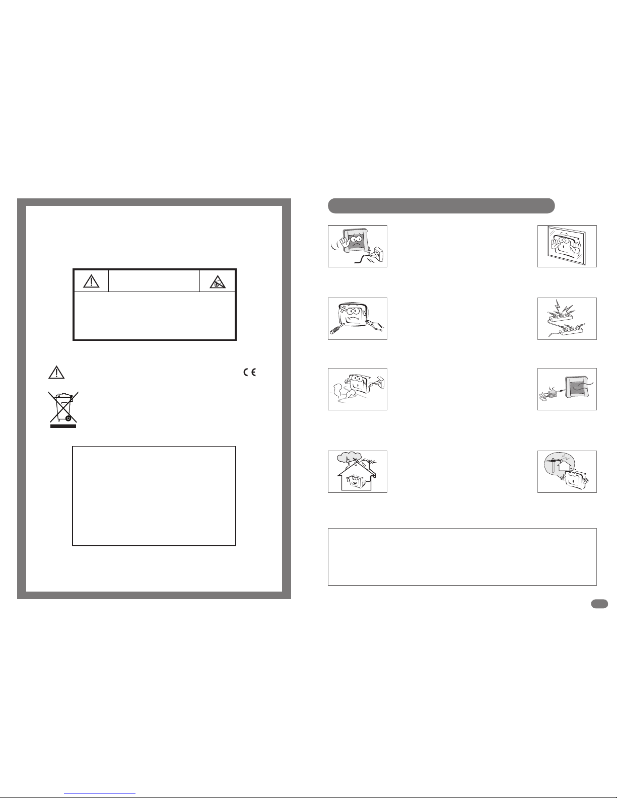
Do not use a damaged socket and do not let the power cord
touch a heat source.
– This may cause an electric shock or fire.
Do not attempt to service the unit.
Contact an authorised dealer or repair service.
– Servicing the unit yourself may cause an electric shock or fire.
If there are any unusual sounds or smells coming from the
unit, unplug it immediately and contact an authorised
dealer or repair service.
– This may cause an electric shock or fire.
If an outside antenna is connected to the unit, ensure the
external to internal cable entry is fully sealed
– This may cause an electric shock or fire.
Do not connect too many extension cords or plugs to
an outlet.
– This may cause a fire.
Keep the power adaptor away from any heat source.
– This may cause a fire.
Ensure the antenna is located away from overhead cables.
– This may cause an electric shock.
Do not add an additional screen or cover the TileVision’s glass.
– The heated screen prevents condensation forming in steamy
rooms and covering the screen may cause the unit to overheat.
Waste Electrical and Electronic Equipment (WEEE) Directive
In the European Union, this symbol indicates that this product should
not be disposed of with household waste. It should be deposited at an
appropriate facility to enable recovery and recycling.
Safety Instructions and Warnings
To prevent injury, the TileVision® must be securely attached to the wall in accordance with the
installation instructions on pages 2 and 3.
The power supply must be connected to a mains socket outlet with a protective earth connection.
The mains plug or the pull switch is the disconnect device and must remain readily operable.
Failure to observe the above safety warnings may invalidate the warranty.
The HD ready logo is a trademark of EICTA
Page 3
2 3
Unpacking and Initial Assembly
Unpacking your TileVision® unit and assembling the back box
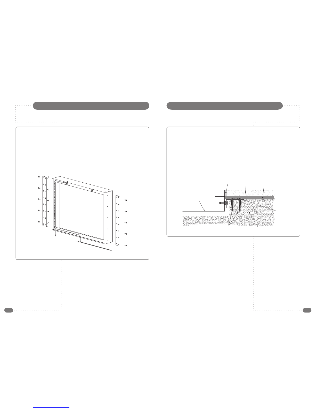
Within the back box there are two right-angled brackets – remove the retaining
screws and take them out.
The three positioning holes on the brackets allow the front edge of the back box to
be fitted flush with the front face of the surrounding tiles. The three positions give a
variation of 11mm, 15mm and 20mm from the front face of the back box and will
allow sufficiently precise alignment.
Once the best position has been established, screw the brackets to the sides of the
back box using the retaining screws, as shown below.
Please note – A technically competent person should carry out the installation
of your TileVision® unit.
Installation and positioning
If this has not already been cut, the 23" unit requires a recess of 635 mm x
455 mm and 90 mm depth from the front face of the tiles.
When positioning the brackets you must ensure that there is sufficient depth to
suit your tile and adhesive thickness so as to set the front edge of the back box
level or just recessed from the surface of the tiled surface.
Fit the back box ensuring that the cable inlets are facing downwards and that the
recess in the wall is chased out to accept the cabling. It is essential that all cables
are fed into the bottom of the unit to prevent the incursion of moisture.
With the angle brackets correctly positioned, secure the back box to the wall.
Wall
Flange
Grout Tile adhesiveTile
Back box
Plug and screw
or wall bolt fixings
Lead to eathing clamp on cold
water pipe from either of the
earthing points inside the
back box (lead not supplied)
☛
Note: Removal of the front glass requires
a force of 100 lbs using a glass sucker,
therefore, the box must be secured to the
wall in such a manner to easily withstand
such a pulling force.
For further instructions please see inside
the rear of the back box itself.
All cables must be routed into the back
box with 500 mm of cable protruding
before installing as shown above.
If connections for HDMI, S-Video, Audio
and SCART (full) are to be used, then the
wall chasing must allow sufficient room
for the cables.
☛
Note: Your qualified electrical installer must
use one of the earthing strap screws as an
earth point to earth the unit to ground.
The lead used must be terminated with a ring
terminal, which, together with the earthing
strap’s ring terminal, is fastened using the
supplied locking washer and screw.
Installing the Back Box
Example of a back box
installed in a ‘solid’ wall
Page 4
4 5
Cabling
Power Requirement (Mains)
TileVision® requires a 13 amp socket outlet connected to a 240 V mains supply via a
readily accessible isolation switch mounted in close proximity to the unit. This
electrical installation shall include an all-pole switch with a contact separation of at
least 3 mm in each pole, both the socket and pull switch must conform to the latest
safety specification and be protected via an RCCD device or similar. This socket must
be fitted in a dry area, away from any moisture (usually in ceiling). The mains plug
should be fitted with a 5 amp fuse.
TileVision® Power Supply (24 V)
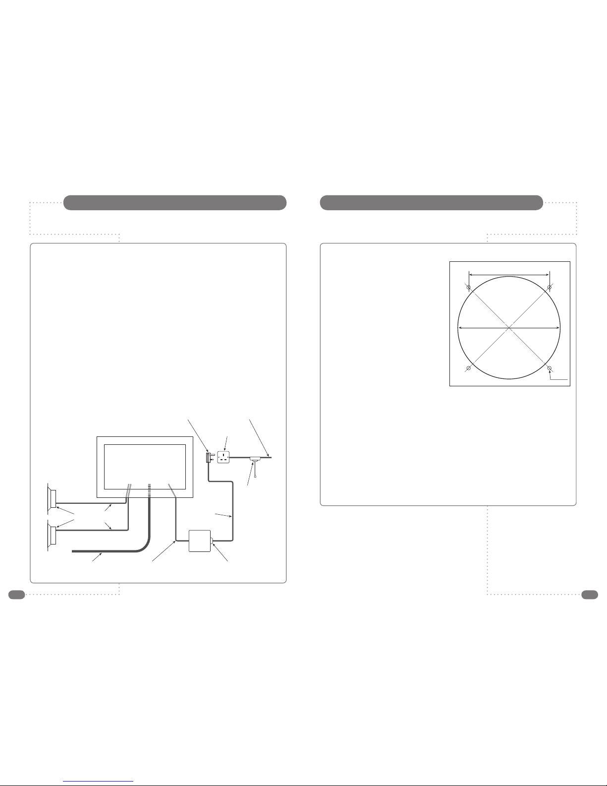
Plug the power supply lead into the mains socket and plug the 24V transformer/power
supply onto the end of this mains lead.
The power supply is not waterproof and so must be positioned in a dry, well-ventilated
area away from any water or moisture. It is fitted with an integral 4 metre lead to feed
the TileVision® unit, this must not be cut, shortened, lengthened, etc. as this could
potentially damage the unit and also has implications regarding the unit’s safety.
Feed the cable from the power supply through a cable inlet into the TileVision® unit –
making sure that there is approximately 500 mm of slack at this end. Any spare cable
should be neatly coiled in a safe place, away from any water or heat generated from
lights, etc.
Please note – All electrical installation should be carried out by a fully qualified
electrician and all fire & safety regulations should be obeyed.
Mains plug 240V mains supply
Isolation
pull switch
Mains power
supply cable
IEC320 socket
24V DC
power
supply
Integral power
supply cable (4m)
TV aerial cable
(not supplied)
Speaker
cable
Speakers
Mains socket
Installing the speakers supplied
For each speaker you should cut a
123 mm diameter hole and four 4.5 mm
holes in the ceiling using the template
supplied. Make sure not to cut through
any ceiling joists, cables, pipes, etc. This
hole should be no more than a 3 metre
cable run from the TileVision® unit.
A 3 metre length of 2-core speaker cable
is provided with the TileVision® unit and
this should be run from the TileVision®
back box to the position of the speaker.
Feed one end of the speaker cable
through the second cable inlet, leaving
approximately 500 mm of slack in the
back box. All slack cable should be
pulled back and left in the ceiling area.
Connect the other end of the speaker
cable to the ceiling speaker by pushing the spade connector onto the appropriate
connector. Ensure the striped conductor is connected to the negative terminal and the
plain conductor to the positive terminal.
Fix the speakers to the ceiling using the screws and fittings supplied.
TV Aerial Feed
Take a 75 Ω feed (CT100 or similar quality cable) from your present television aerial or
distribution system and feed this into the TileVision® back box through the third cable
inlet. Terminate with a standard COAX termination. Ensure that the cable is not kinked.
Back box aperture protective cover
The back box is now correctly installed, please push the aperture cover provided into
the front of the back box (printed side outward) to protect the sealing flanges from
damage whilst awaiting the installation of the front assembly.
Speakers and Aerial Feed
☛
Note: The signal level fed to the set must be at
least 60dB/1millivolt or the picture may be noisy.
A TV Distribution Amplifier may be required if you
are in an area of weak signal or if other televisions
are already being fed from the aerial. If in doubt,
consult a qualified aerial technician.
Refer to pages 5 to 9 of the TileVision® Instruction
Manual for further information on speaker phasing
and additional connections for HDMI, S-Video,
Audio and SCART (full).
5" TEMPLATE
ø4.5mm
(11/64") HOLE
97mm (37/8")
123mm (47/8")
Template shown here at 50% actual size
Page 5

TV/23/BA3 – 23" TileVision® Back Box Installation Instructions – October 2007 – Part No. TVS/00325/04
PORTER LANCASTRIAN LIMITED
www.tilevision.tv
 Loading...