

Page 1
P/N 92230401 • Rev A• 3/25/2008
Warranty: If this unit fails during the warranty period, contact tii customer service to authorize return. Unit may be returned prepaid.
Model VIS-3
VOICE INTERCOM SWITCH
Installation Note
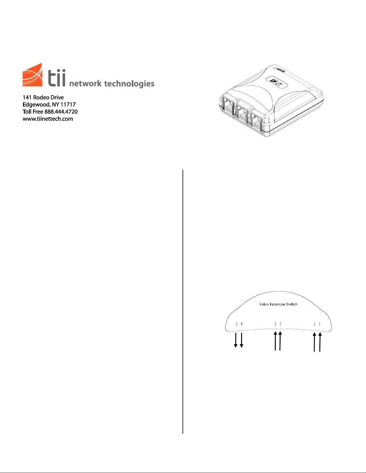
From Digital
Voice Service
To Phone at
Premises
3
2
2
3
From
DAS/Intercom
Figure 1
2
3
Digital Voice
VIS-3
Phone
Intercom
DAS
Pins 2,3
Pins 2,3
Pins 2,3
Output
Input
Input
Phone
Premises
Description
1. The tii VIS-3 (Voice Intercom Switch) is a
microprocessor controlled module that
provides seamless switching from Digital
Voice Service to Door Answering Systems
(DAS)/Intercom service in multiple dwelling
unit’s (MDU’s).
2. The tii VIS-3 enables attending to the
DAS/Intercom calls while using Digital Voice
Service. The VIS-3 provides call waiting type
functionality between the two services.
3. The tii VIS-3 is for indoor use only.
4. The tii VIS-3 switches to the DAS/Intercom
when the Digital Voice Service loses power.
5. The tii VIS-3 provides line hold function while
answering the DAS intercom.
Installation
1. Locate a suitable flat, dry area to install the
unit.
2. The existing telephone wiring to the MDU may
need to be modified to enable all telephone
connections in the MDU to connect through
the VIS-3.
3. Locate the first appearance of the DAS
Intercom telephone connection wall jack to the
MDU. Rewire the connections so that the
incoming wires from the DAS intercom are
connected to pins 2 & 3 of the RJ-11 marked
DAS/Intercom Input. Refer to Figure 2 for a
rewiring example.
Page 2
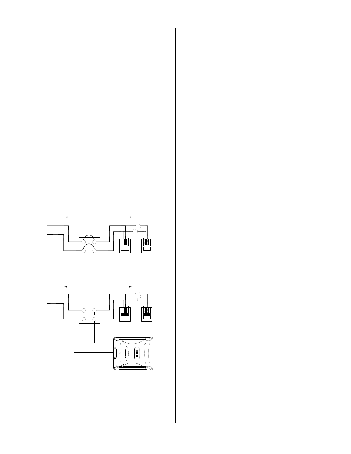
Figure 2
MODIFIED WIRING
WALLPLATE
FIRST PHONE LINE
APPEARANCE
UNMODIFIED WIRING
MDU
WALLJACK
ADD'L
WALLJACK'S
MDU
12 3
4
12 3
4
TELCO / DAS / INTERCOM
DAS / INTERCOM
PREMISES
PHONES
Premises
Phone
VIS-3
Digital Voice Service Power
Phone
DAS
Intercom
Pins 2,3 Pins 2,3 Pins 2,3
Output
Input
Input
Digital Voice
TELCO / DAS / INTERCOM
WALLPLATE
FIRST PHONE LINE
APPEARANCE
WALLJACK
ADD'L
WALLJACK'S
12 3
4
12 3
4
WIRES FROM DIGITAL
VOICE SERVICE
Wiring
Premise Phones
1. Plug one end of the RJ-11 cable to the phone
at premises receptacle on the VIS-3. Connect
the other end of the cable to the phone
connection to the whole premises.
Digital Voice Service Device
1. Plug one end of another RJ-11 cable to the
Digital Voice Service receptacle on the VIS-3.
Connect the other end to the RJ11 output from
the voice output of ONT (Optical Network
Terminal) (Figure 1).
Intercom
1. Plug one end of the third RJ-11 cable to the
DAS / Intercom receptacle on the VIS-3
(Figure 2).
2. Connect the other end of the cable to the
rewired (Per Figure 2) intercom input.
Testing
1. On power-up the unit is in Digital Voice Mode.
The LED should start flashing within a few
seconds of powering up (Figure 3).
2. The VIS-3 will automatically switch to DAS /
Intercom Mode when the Local Digital Voice
Service power is disconnected.
3. When the DAS / Intercom rings and the Digital
Voice line is on hook, the VIS-3 will switch to
the DAS / Intercom. After answering the
intercom or the ringing has stopped, the VIS-3
will switch back to Local Digital Voice Service
mode.
4. To answer the DAS / Intercom when the
Digital Voice line is in use, press the flash
hook switch momentarily, this will hold the
Digital Voice line and at the same time switch
the VIS-3 to DAS / Intercom mode.
5. When finished with the DAS / Intercom call,
press the flash hook switch momentarily to
recover the Voice line. In some case the flash
switch may need to be activated twice to
recover the voice line.
 Loading...