

Page 1
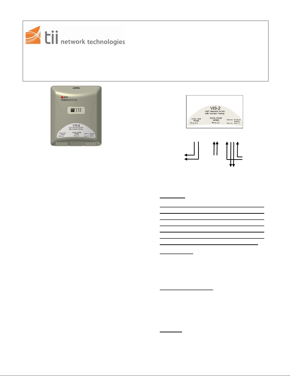
To other
Phone’s in Premise
VoIP
From
3
tii VIS-2
Phone at
location
3
2
2
1
2
3
4
Intercom Input
Figure 1
141 Rodeo Drive
Edgewood, NY 11717 tii VIS-2
Toll Free 888.844.4720 VoIP INTERCOM SWITCH
www.tiinettech.com Rev B 12/07
INSTALLATION NOTE
2 is supplied with double faced tape for
secure installation.
1. DESCRIPTION
1.1 The tii VIS-2 (VoIP Intercom Switch) is a
microprocessor controlled module that
provides seamless switching between VoIP
4. WIRING
service and Intercom calls in multiple
dwelling unit’s (MDU’s).
1.2 The tii VIS-2 is able to attend the Intercom
calls while using VoIP service. The VIS-2
provides call waiting type functionality
between the two services.
1.3 The tii VIS-2 is for indoor use only.
1.4 The tii VIS-2 does not draw any current from
the Intercom line.
CAUTION:
On the Intercom Input Pin’s 1 and 4 are
wired as Intercom Input, Pin’s 2 and 3 are
wired for local customer phone output
(Connected in parallel to Local A phone
output). Confirm interface wiring prior to
plugging in device. Damage to the digital
modem can occur if not properly wired.
House Phone
2. WARRANTY
4.1 Plug one end of the RJ-11 cable to the
2.1 See tii Warranty. If this unit fails during the
warranty period, contact tii customer service
to authorize return and return the unit
house phone receptacle on the VIS-2
labeled Local A Phone. Plug the other
end to the phone at location (Figure 1).
prepaid. Units that fail due to normal wear or
abuse should be discarded.
3. INSTALLATION
Digital Phone Modem
4.2 Plug one end of another RJ-11 cable to
the digital phone modem receptacle on
3.1 Remove the unit from the bag and inspect it
for damage. If damaged, request another
unit.
3.2 Locate a suitable flat, dry area to install the
the VIS-2. Plug the other end to the RJ11
output from MTA/EMTA of cable modem
(Figure 1) labeled Digital Phone Modem.
Intercom
unit.
4.3 Plug one end of the third modified (See
3.3 The VIS-2 should be located near the first
appearance of the Intercom Phone. The VIS-
Caution Note Above) RJ-11 cable to the
intercom receptacle on the VIS-2 (Figure
tii P/N: 92225501
Page 2
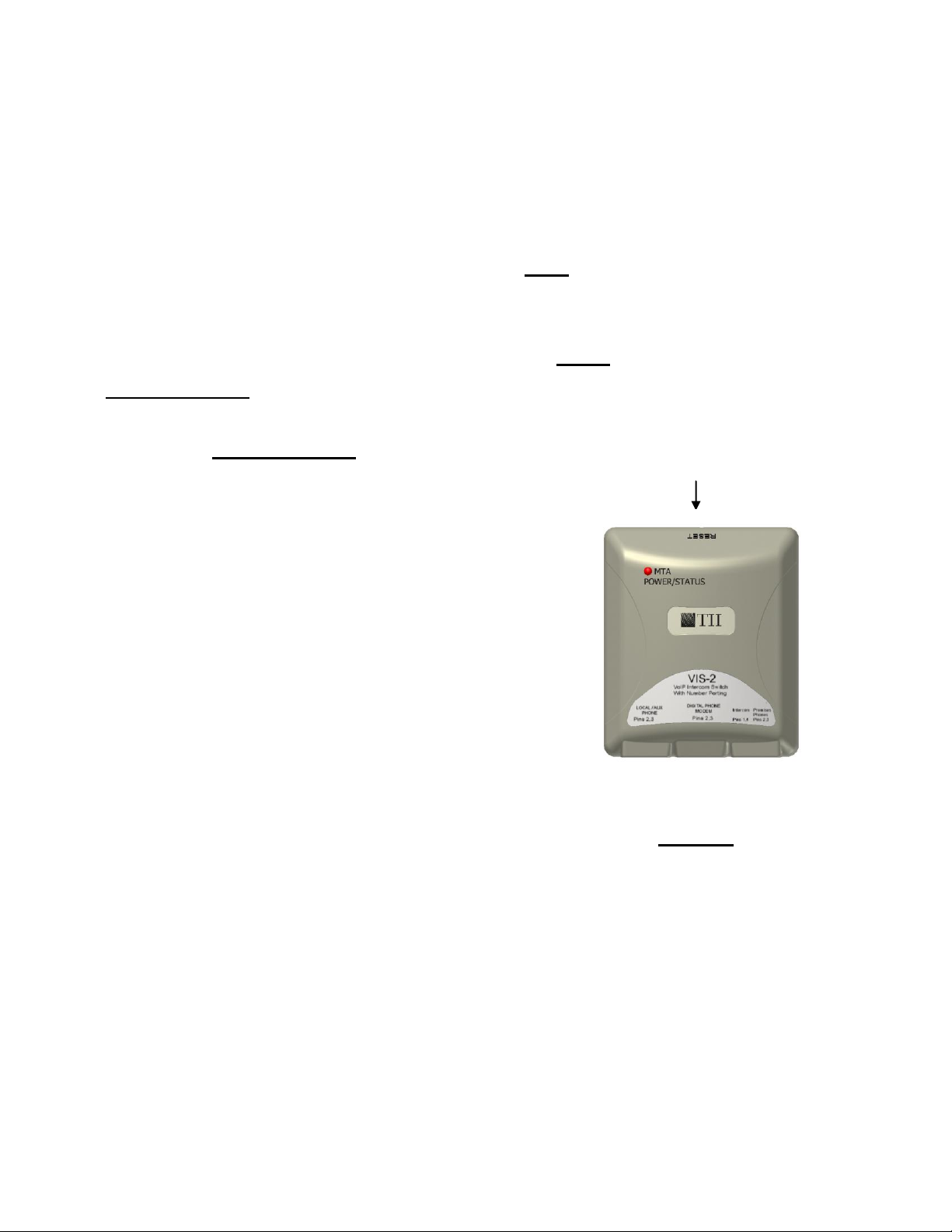
Reset Button Opening
Figure 2
1). Pins 1 and 4 must be used for
Intercom Input.
4.4 Wire the other end of the cable to the
intercom input and other phone connections
in multiple dwelling units.
5. TESTING
Note: Hardware reset is required to
switch device to its initial state after
installation. The initial state for the VIS-2
is intercom mode.
5.1 To reset this unit:
Insert an RJ11 plug from the MTA lead into
the “Digital Phone Modem” jack. Depress the
reset button within 3 seconds of powering
the jack. (Figure 2).
5.2 With power applied after the reset switch on
the VIS-2 is pressed the unit is in Intercom
Mode. The LED should be flashing Red.
5.3 The VIS-2 will automatically switch to VoIP
Mode after the second ring of the VoIP line.
The LED should be flashing Green. Once
the VIS-2 has been switched to VoIP Mode it
will stay in this mode and only temporarily
switch over to answer intercom calls.
5.4 When the Intercom is ringing and VoIP is on
the hook, the VIS-2 will switch to intercom to
allow the customer to answer it. After
answering the intercom or the ringing has
stopped, the VIS-2 will switch back to VoIP
mode. The LED should be flashing Orange.
5.5 To answer the intercom when the VoIP is off
the hook, press the hook switch
momentarily. The VoIP line will be placed on
hold and at the same time switch the VIS-2
to intercom mode. The LED should be
flashing Orange. When you are finished with
intercom press the hook switch momentarily
to recover the status of the VoIP line.
Note: The reset switch on the VIS-2 has to
be pushed and held for a few seconds after
power-up in order for the device to switch to
Intercom Mode (Figure 2).
5.6 Gently using a small blunt object push
the reset button, see Figure 2 for
location.
CAUTION:
TO AVOID PERMANENT DAMAGE TO RESET
BUTTON DO NOT USE EXCESSIVE FORCE
OR A POINTED OBJECT TO ACTIVATE THE
RESET BUTTON.
tii P/N: 92225501
 Loading...