

Page 1
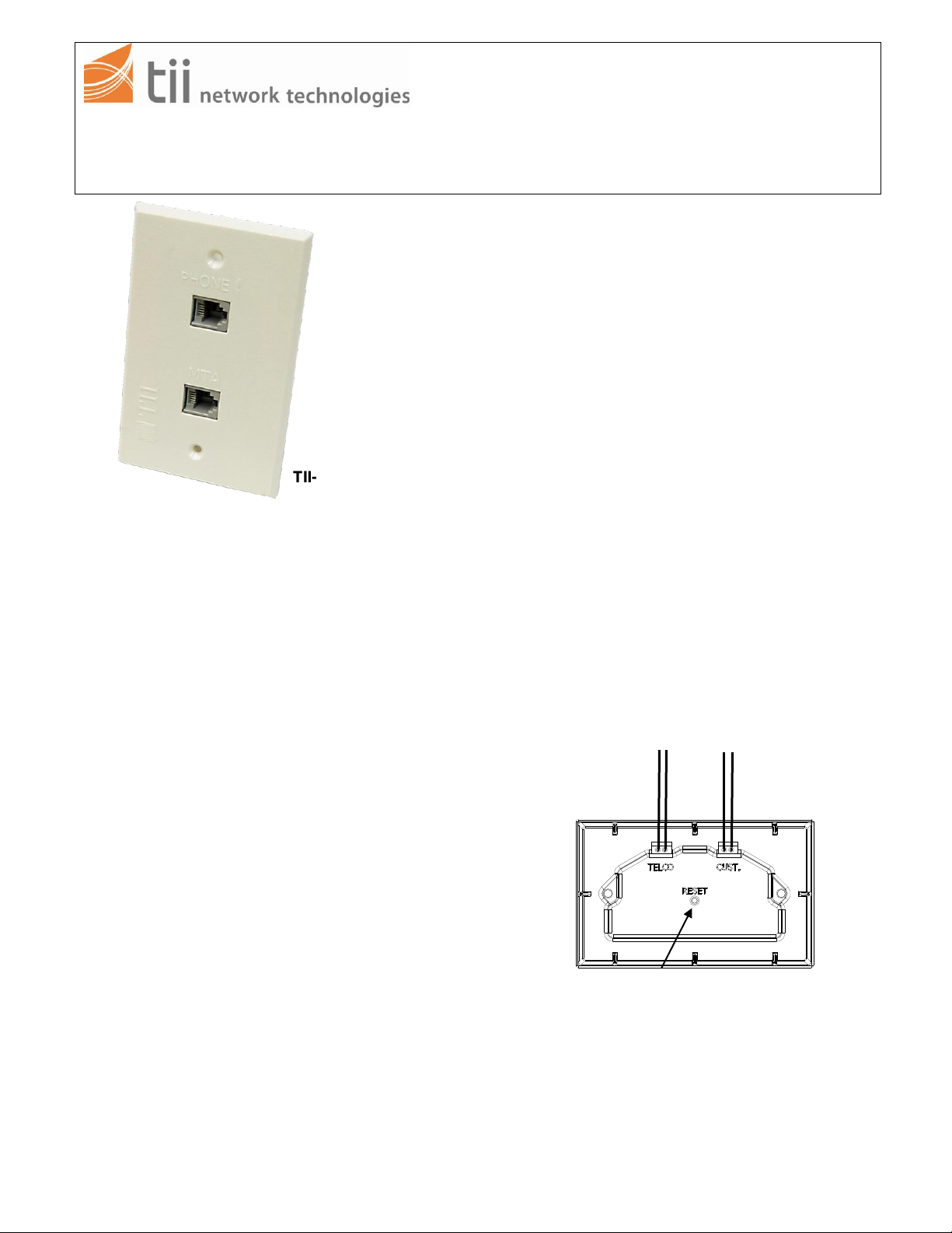
TII-SVWJ
Customer
wiring
Telco
wiring
Reset
Switch
Figure 1
141 Rodeo Drive tii SVWJ Series
Edgewood NY11717 SWITCHABLE VOICE WALL JACK
Customer Service/Sales 888-844-4720 Rev C 03/08
INSTALLATION NOTE
1. DESCRIPTION
1.1 The TII-SVWJ is a microprocessor controlled
circuit that provides seam less switching
from Telco service to digital phone service.
1.2 The TII-SVWJ utilizes gel sealed insulation
displacement terminations that provide
reliable connectivity.
1.3 The second ringing voltage appearance on
the digital phone service initiates the switch
over.
1.4 The TII SVWJ is for indoor use only.
1.5 The SVWJ gets it’s power from the Digital
Voice Service line and switches after
validating telephone ringing voltage
presence.
1.6 The SVWJ can be reset by using the reset
push button access provided on the back of
the device. The circuit needs to be powered
to activate switching in.
1.7 IDC rockers are used to terminate 26-22
AWG solid wire.
1.8 The SVWJ comes equipped with a
galvanized steel wall mounting plate for use
in existing retrofit construction installations.
2. WARRANTY
See TII Warranty. If this unit fails during the
warranty period, the factory should be
requested to authorize return. Return the
unit prepaid. Units that fail due to normal
wear or abuse should be discarded.
3. INSTALLATION
3.1 Remove the unit from the bag and inspect it
for damage. If damaged, obtain another unit
3.2 Locate the existing phone jack outlet box
that first enters the premises and disconnect the
incoming telephone service to the RJ-11.
3.3 Place the SVWJ on flat surface so IDC’s are
easily accessible (See Figure 1).
3.3 Pull both rockers to the full open positions,
insert wires as shown in Figure 1 until they
bottom out, do not strip wires.
3.4 Push both rockers to the closed position for
termination.
3.5 Using an RJ-11 plug wire the digital voice
service wires from the ATA/EMTA to the MTA
receptacle on the front face plate.
3.6 Connect existing phone from this location
into the phone RJ-11 receptacle on the front
face plate.
TII P/N: 92222401
Page 2
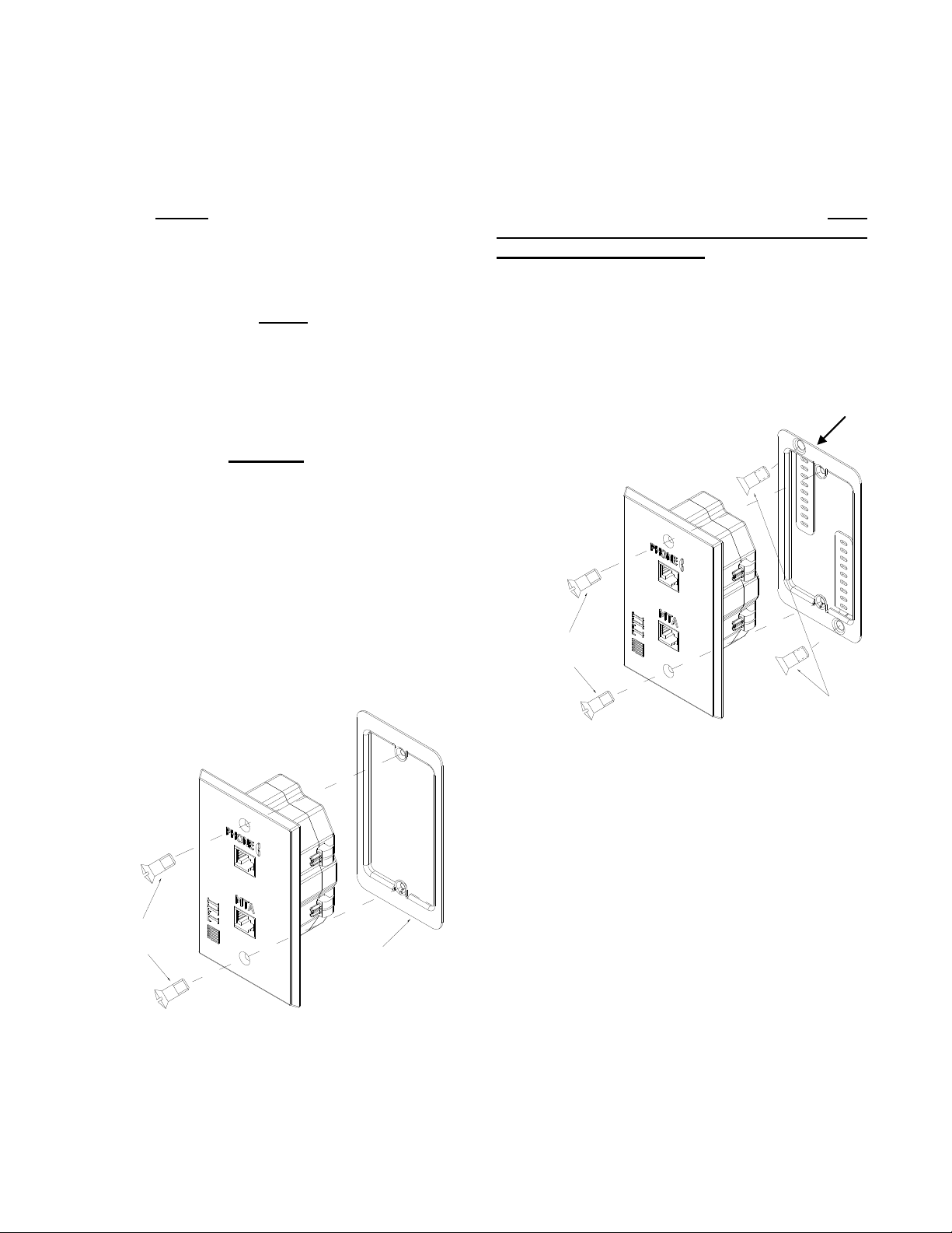
#6 Drywall Screws
#6 Oval Head Machine Screws
Figure 3
Wall Mounting Plate
Existing Junction Box
#6 Oval Head Machine Screws
Figure 2
3.7 RESET
3.7.1 Confirm that the power is connected to
the MTA RJ-11 receptacle of the SVWJ.
3.7.2 Gently push the reset button once with
a blunt object to ensure the service to the
customer is from the Telco Service Provider
(See Figure 1).
NOTE:
THE RESET SWITCH IS DISABLED DURING
RINGING VOLTAGE PRESENCE AND TEN
SECONDS AFTER THE LAST RINGING
VOLTAGE.
CAUTION:
TO AVOID PERMANENT DAMAGE TO
RESET BUTTON DO NOT USE
EXCESSIVE FORCE OR A POINTED
OBJECT TO ACTIVATE THE RESET
BUTTON.
3.9 Existing Construction Installation
3.9.1 Cut drywall 2” W x 3.5” L in the location
where the SVWJ is going to be mounted. Prior
to cutting hole confirm that there are no
obstructions behind wall.
3.9.2 After drywall has been cut, install the
wall mounting plate. Bend the two mounting tabs
behind the drywall and secure the mounting
plate with the supplied drywall screws (See
Figure 3). Align the mounting tab slots while
tightening the screws.
3.8 Dress the wires properly inside the
junction box and secure the SVWJ to the
junction box using the supplied #6 oval head
screw’s (See Figure 2).
3.9.3 Dress the wires properly inside the wall
mounting plate and secure the SVWJ to the
junction box using the supplied #6 oval head
screw’s (See Figure 3).
TII P/N: 92222401
 Loading...