

Page 1
P/N 92231001 • Rev A• 4/15/2008
Warranty: If this unit fails during the warranty period, contact tii customer service to authorize return. Unit may be returned prepaid.
Model SVMWT
Switchable Voice Module
Wire Terminal
Installation Note
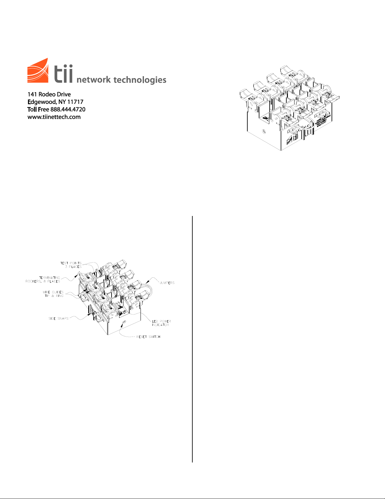
Features
3. The SVMWT gets its power from the Digital
Voice Service line, and switches to Digital
Voice Service after validating telephone
ringing voltage presence on this line. The
green LED will blink slowly when the SVMWT
is receiving power from the Digital Voice
Service Line.
4. The SVMWT can be reset by using the reset
push button accessible on the side wall of the
device. The SVMWT must be powered by the
ATA / EMTA for the reset function to operate.
5. IDC rockers are designed to accept 26-22
AWG solid wire for termination.
WARRANTY
1. See tii Warranty. If this unit fails during the
warranty period, contact tii customer service to
Figure 1
authorize return and return the unit prepaid.
Units that fail due to normal wear or abuse
should be discarded.
Description
1. The tii SVMWT can be mounted indoors or
outdoors. If mounting outdoors the tii SVMWT
should be mounted in a weatherproof housing.
2. The tii SVMWT has been designed to provide
automatic switching of telephony service from
Telco to Digital Voice when the number is
ported. Porting is completed by second ringing
voltage appearance on Digital Voice Service
line.
INSTALLATION
1. Remove the unit from the bag and inspect it
for damage. If damaged, obtain another unit.
2. Line up with side snaps in the 168 enclosure
and press into place.
3. Lift the blue rocker for the digital voice service
wires (MTA) to the full up position. (See Fig. 2)
Page 2
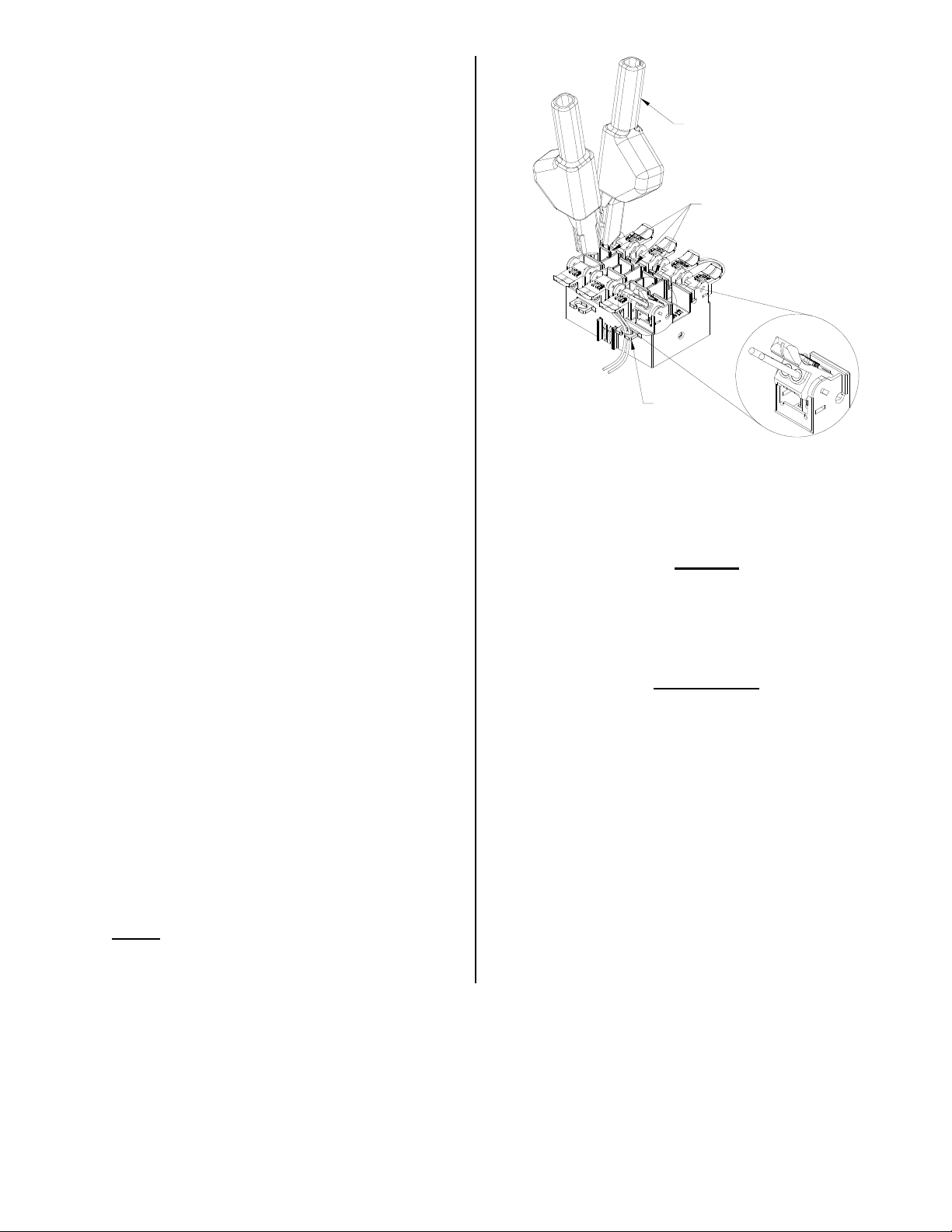
NOTE: Wires do not require stripping for
TEST CLIPS
(NOT INCLUDED)
WIRE
LOOM
TEST POINTS
FULL UP POSITION
terminations to the IDC rockers
described in the following steps.
4. Insert the Digital Voice Service wires from
ATA / EMTA into wire guides simultaneously
until they bottom-out. While holding the wires
in position, terminate them into the MTA (Blue)
rocker by lowering it to the full DOWN position.
(See Fig. 2) If the ATA / EMTA is supplying
power to the SVM, the green MTA power LED
provided on the line will start to blink.
5. Disconnect the customer premises wiring from
the Telephone Network Interface Device
(NID). Install a wire pair from the Telephone
NID (where the customer premises wiring was
disconnected) to the rocker labeled Tel
(Green/Red) on the SVMWT. Follow the
procedure described in step 4 for the wire pair
termination.
6. Re-terminate customer premises wires onto
the Green/Red rockers provided on the
SVMWT. Straighten the ends of the wires, cut
kinked and stripped ends. Follow the
procedure described in step 4 for the wire pair
termination.
7. If a security alarm is installed at the customer
premises, remove the Green/Red wire
jumpers from the Orange S-Out and S-In
rockers by lifting the rockers up and pulling the
jumper wires out. (See Fig. 1)
8. Terminate the wire pair going to the security
alarm system in the rocker marked S-Out.
Terminate the wire pair returning from the
security alarm system in the rocker marked SIn.
9. To keep wire pairs organized, route them
through the molded wire looms. (See Fig. 2)
10. IMPORTANT: This unit MUST be reset during
initial installation. Refer to procedure
described below for MTA Power Reset.
THE RESET SWITCH IS DISABLED DURING
RINGING VOLTAGE PRESENCE AND TEN
SECONDS AFTER THE LAST RINGING VOLTAGE.
TO AVOID PERMANENT DAMAGE TO RESET
BUTTON DO NOT USE EXCESSIVE FORCE OR A
POINTED OBJECT TO ACTIVATE THE RESET
Figure 2
NOTE:
CAUTION:
BUTTON.
RESET
1. Confirm that the power is connected to the
MTA (Blue) rocker of SVMWT.
2. Gently push the reset button once with a blunt
object to ensure the service to the customer is
switched from Digital to Telco. (See Fig. 1)
 Loading...