

Page 1
SVM-2-0
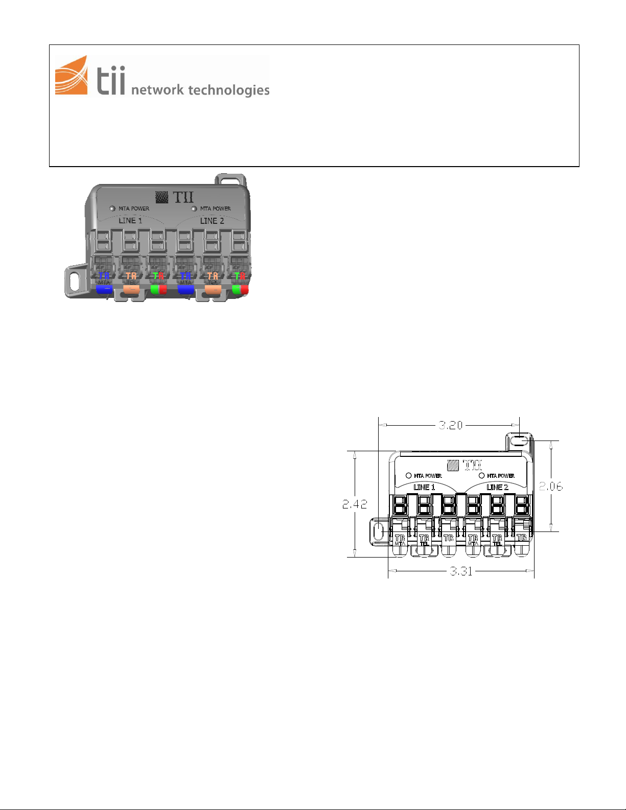
Figure 1
141 Rodeo Drive tii SVM-2 Series
Edgewood, NY 11717 Multi-Line Switchable Voice Module
Toll Free 888.844.4720 Rev C 12/07
www.tiinettech.com INSTALLATION NOTE
1. DESCRIPTION
1.1 The tii SVM-2 Series Multi-Line Switchable
Voice Module is used when porting up to two
existing telephone numbers.
1.2 The tii SVM-2 has been designed to provide
automatic switching of a customer’s
telephony provider from Telco to Digital
Voice Service automatically after installation
when the number is ported.
1.3 The tii SVM-2 can come equipped with an
optional secondary telephone line surge
protection to enhance Digital Phone service
reliability.
1.4 The SVM-2 should only be used for indoor
applications, if mounting outdoors the SVM-2
should be mounted in a weatherproof
housing.
1.5 The SVM-2 is powered from the Digital Voice
Service line, and switches to Digital Voice
Service after validating telephone ringing
voltage presence on this line. The green
LED will blink slowly when the SVM is
receiving power from the Digital Voice
Service Line.
1.6 The SVM-2 may be reset by using the reset
push button accessible on the side wall of
the device. The SVM-2 must be powered by
the ATA / EMTA for the reset function to
operate.
1.7 IDC rockers are used to terminate 26-22
AWG solid wire.
2. WARRANTY
2.1 See tii Warranty. If this unit fails during the
warranty period, contact tii customer service
to authorize return and return the unit
prepaid. Units that fail due to normal wear or
abuse should be discarded.
3. INSTALLATION (Line 1)
3.1 Remove the unit from the bag and inspect it
for damage. If damaged, obtain another unit.
3.2 Locate a suitable flat, dry area to install the
unit.
3.3 Prior to installing the SVM-2 pre-drill the (2)
mounting location holes to accommodate #8
self tapping screws (See Figure 1).
3.4 Lift the blue rocker for the digital voice
service wires (MTA) to the full up position.
DO NOT strip wires. (See Figs 2 & 3)
3.5 Insert the Digital Voice Service wires from
ATA/EMTA into wire guides simultaneously
until they bottom-out. While holding the
wires in position, terminate them into the
MTA (Blue) rocker by lowering it to the full
DOWN position. (See Figs 2 & 3) If the
ATA/EMTA is supplying power to the SVM,
tii P/N: 92224401
Page 2
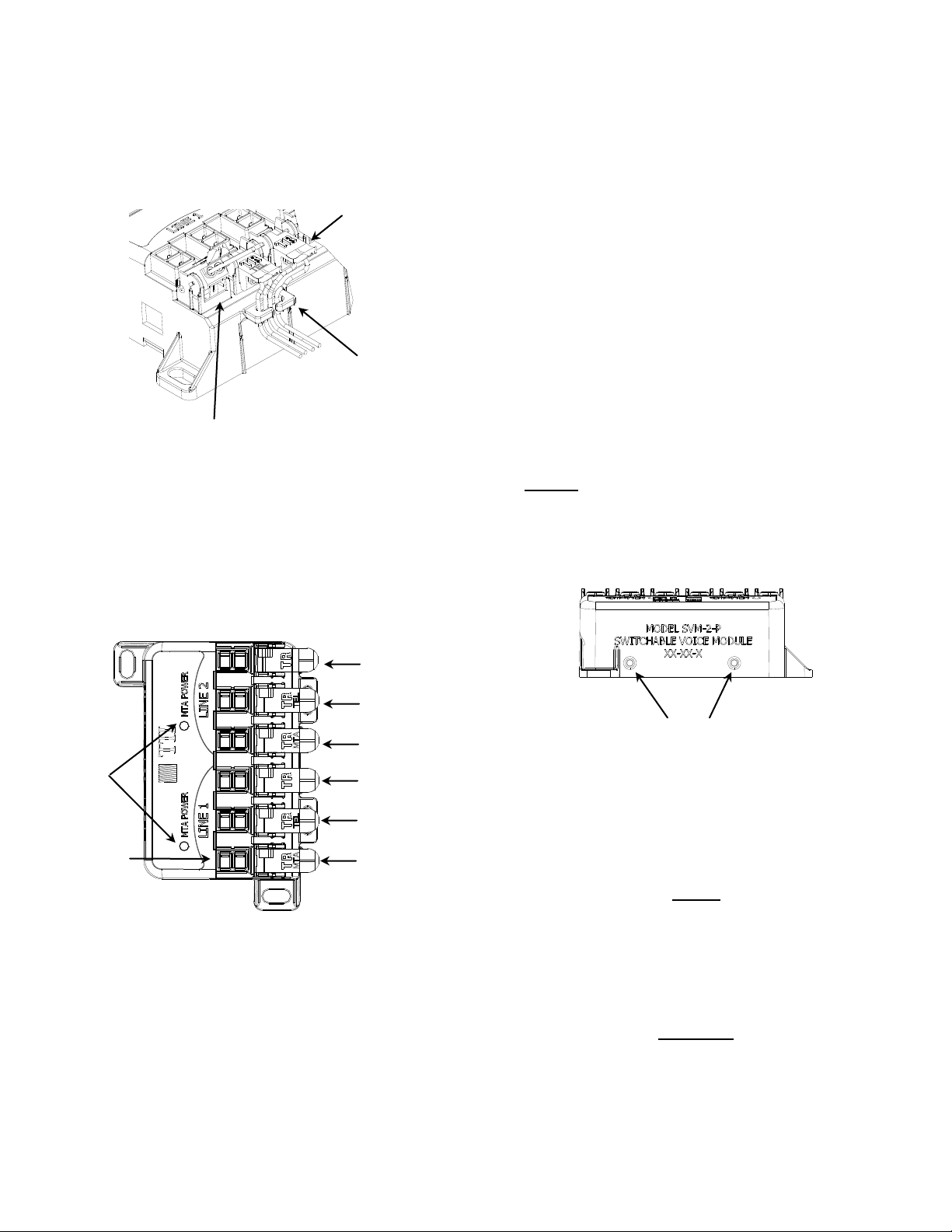
Figure 2
Terminated rocker
Wire loom
Full Up Position
Figure 4
* RESET BUTTON’S
CUSTOMER WIRING (L1)
TEST POINTS
MTA LED’S
CUSTOMER WIRING (L2)
Figure 3
DIGITAL VOICE
SERVICE WIRES (L2)
TELCO WIRES (L2)
TELCO WIRES (L1)
DIGITAL VOICE
SERVICE WIRES (L1)
the green MTA power LED provided on the
line will start to blink.
3.6 Disconnect the customer premise wiring
from the Telephone Network Interface
Device (NID). Straighten the ends of the
wires, cut kinked and stripped ends. Lift the
Green/Red rocker to full up position. Insert
wires into the Customer wire rocker holes.
While assuring that wires are fully inserted
lower the rocker to fully seated position (See
Fig 3).
3.7 Connect the Telco Service using a wire pair
from the Telephone NID to the rocker
labeled TEL (orange). Follow procedure
described above for the wire pair termination
(See Figs 2 & 3).
3.8 To keep wire pairs organized, route them
through the molded wire looms. (See Fig. 2)
4. Installation (Line 2)
4.1 Follow steps 3.4 to 3.8 to connect Line 2
through the SVM-2.
5 RESET
IMPORTANT: This unit MUST be reset during
initial installation. Follow these instructions to
reset the unit.
5.1 Confirm that the power is connected to the
MTA (Blue) rocker of SVM-2 by observing
green LED blinking.
5.2 Gently push the reset button once with a
blunt object to ensure the service to the
customer is from the Telco Service Provider
(See Figure 4).
NOTE:
THE RESET SWITCH IS DISABLED DURING
RINGING VOLTAGE PRESENCE AND TEN
SECONDS AFTER THE LAST RINGING
VOLTAGE.
CAUTION:
TO AVOID PERMANENT DAMAGE TO RESET
BUTTON DO NOT USE EXCESSIVE FORCE
OR A POINTED OBJECT TO ACTIVATE THE
RESET BUTTON.
tii P/N: 92224401
 Loading...