

Page 1
P/N 92220301 • Rev J• 9/2/2008
Warranty: If this unit fails during the warranty period, contact tii customer service to authorize return. Unit may be returned prepaid.
Model SVN-SERIES Switchable Voice Network Interface Device
SVM-SERIES Switchable Voice Module
Patents Pending
Installation Note
Description
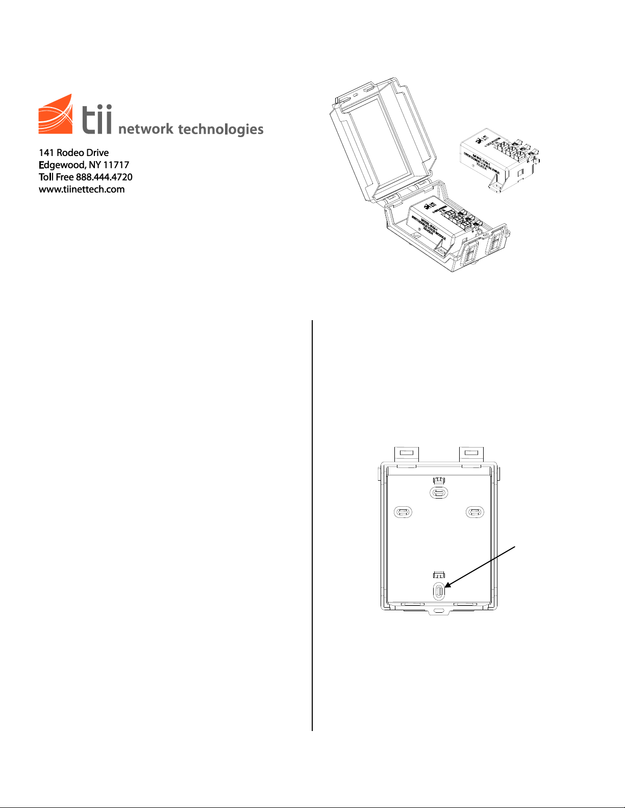
Knockouts
(x4)
Installation
1. This combined Installation Note covers the
description and installation of the TII Series
SVN and SVM. The SVN is enclosed in an
indoor/outdoor housing, while the SVM is
supplied as an individual module.
2. The SVN and SVM can be mounted indoors or
outdoors using the standard hardware
provided. If mounting outdoors the SVN and
SVM should be mounted in a weatherproof
housing.
3. The SVN and SVM have been designed to
provide automatic switching of a customer’s
telephone provider from Telco to Digital Voice
Service automatically after installation when
the number is ported.
4. The SVN or SVM get its power from the Digital
Voice Service line, and switches to Digital
Voice Service after validating telephone
ringing voltage presence on this line. The
green LED will blink slowly when the SVM is
receiving power from the Digital Voice Service
Line.
5. The SVN or SVM can be reset by using the
reset push button accessible on the side wall
of the device. The SVN or SVM must be
powered by the ATA / EMTA for the reset
function to operate.
6. IDC rockers are used to terminate 26-22 AWG
solid wire.
1. Locate a suitable flat, dry area to install the
unit.
2. Prior to installing the SVN, decide on the (2)
knockout locations that are to be used (See
Figure 1). Using a flat bladed screwdriver
knockout the (2) locations and use two #8
screws to mount the unit.
Figure 1
Wiring
1. Lift the blue rocker for the digital voice service
wires (MTA) to the full up position. DO NOT
strip wires. (See Figures 2 & 3)
Page 2
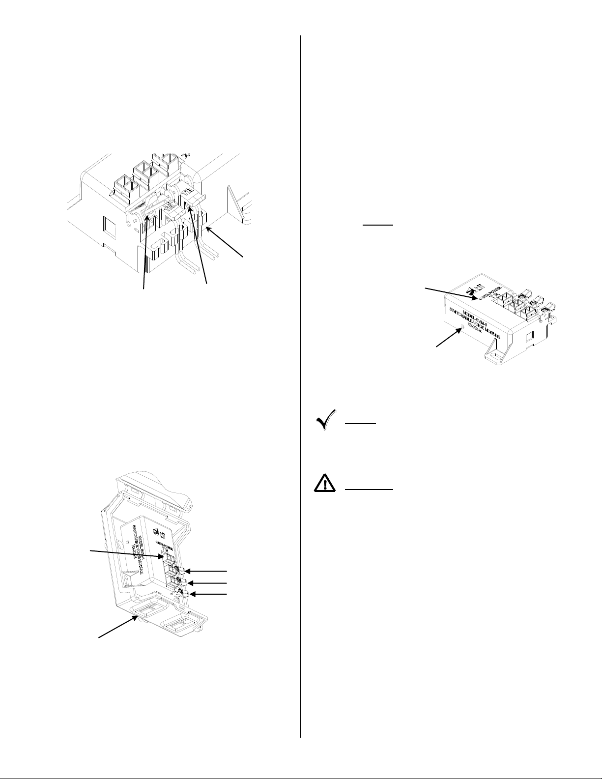
2. Insert the Digital Voice Service wires from
Terminated rocker
Wire loom
Full Up Position
LED MTA
Power Indicator
*Reset Button
Opening
Telco Wires
Test Points
Customer Wiring
Digital Voice
Service Wires
Grommet
ATA/EMTA through the enclosure grommets
shown in Figure 3 and into wire guides
simultaneously until they bottom-out. While
holding the wires in position, terminate them
into the MTA (Blue) rocker by lowering it to the
full DOWN position (See Figures 2 & 3). If the
ATA/EMTA is supplying power to the SVM, the
green MTA power LED provided on the line
will start to blink.
Figure 2
3. Disconnect the customer premise wiring from
the Telephone Network Interface Device
(NID). Straighten the ends of the wires, cut
kinked and stripped ends. Pass the customer
telephone wire through the enclosure (Cust)
grommet. Lift the Green/Red rocker to full up
position. Insert wires into the Cust wire rocker
holes. While assuring that wires are fully
inserted, lower the rocker to fully seated
position (See Figure 3).
Figure 3
5. To keep the wire pairs organized, route them
through the molded wire looms. (See Figure
2).
6. Dress the wires properly inside the housing
and close the cover. A suitable tie wrap can
be used for added security.
7. IMPORTANT: This unit MUST be reset during
initial installation. For resetting the MTA
Power, refer to the reset instructions below.
Reset
1. Confirm that the power is connected to the
MTA (Blue) rocker of SVN / SVM.
2. Gently push the reset button once with a blunt
object to ensure the service to the customer is
from the Telco Service Provider (See Figure
4).
Figure 4
NOTE: THE RESET SWITCH IS DISABLED
DURING RINGING VOLTAGE PRESENCE AND
TEN SECONDS AFTER THE LAST RINGING
VOLTAGE.
CAUTION: TO AVOID PERMANENT DAMAGE
TO RESET BUTTON, DO NOT USE EXCESSIVE
FORCE OR A POINTED OBJECT TO ACTIVATE
THE RESET BUTTON.
4. Connect the Telco Service using a wire pair
from the Telephone NID to the rocker labeled
TEL (orange). Follow the procedure described
above for the wire pair termination (See
Figures 2 & 3).
 Loading...