

Page 1
P/N 92237501 • Rev B• ECN 12-072 • 3/2/2012
Warranty: If this unit fails during the warranty period, contact tii customer service to authorize return. Unit may be returned prepaid.
25 Pair unit shown
Models OF025PFNOPNST1
OF050PFNOPNST1
OF100PFNOPNST1
FIXED OUTDOOR BET
Installation Note
NOTE:
SPLICE CHAMBER
PROTECTOR BLOCK
GROUND BAR
MS^2 TOOL HOLDER BRACKET
TOOL-LESS IDC TERMINALS
To ensure the proper fusing integrity to maintain
the UL Listing, only use No 22 or 24 AWG
incoming wire.
4. BETs are surface mount unit to be mounted
on the wall. Multiple units can be mounted one
above the other and wired from the same OSP
cable.
Feature
Description
1. The TII Fixed Outdoor BET panels are
compact terminals for applications in
commercial and residential buildings. The
BETs are available in pair counts of 25, 50
and 100, are equipped with protection fields
that accept 5 pin style protector modules and
utilize tool-less IDC outputs. IDC outputs are
used to terminate 26-22 AWG solid wires. MS²
connector bracket is provided to ease
connector termination.
2. BETs are supplied with 6 AWG ground strap
and ground block.
3. BETs are fabricated from powder coated steel.
Page 2
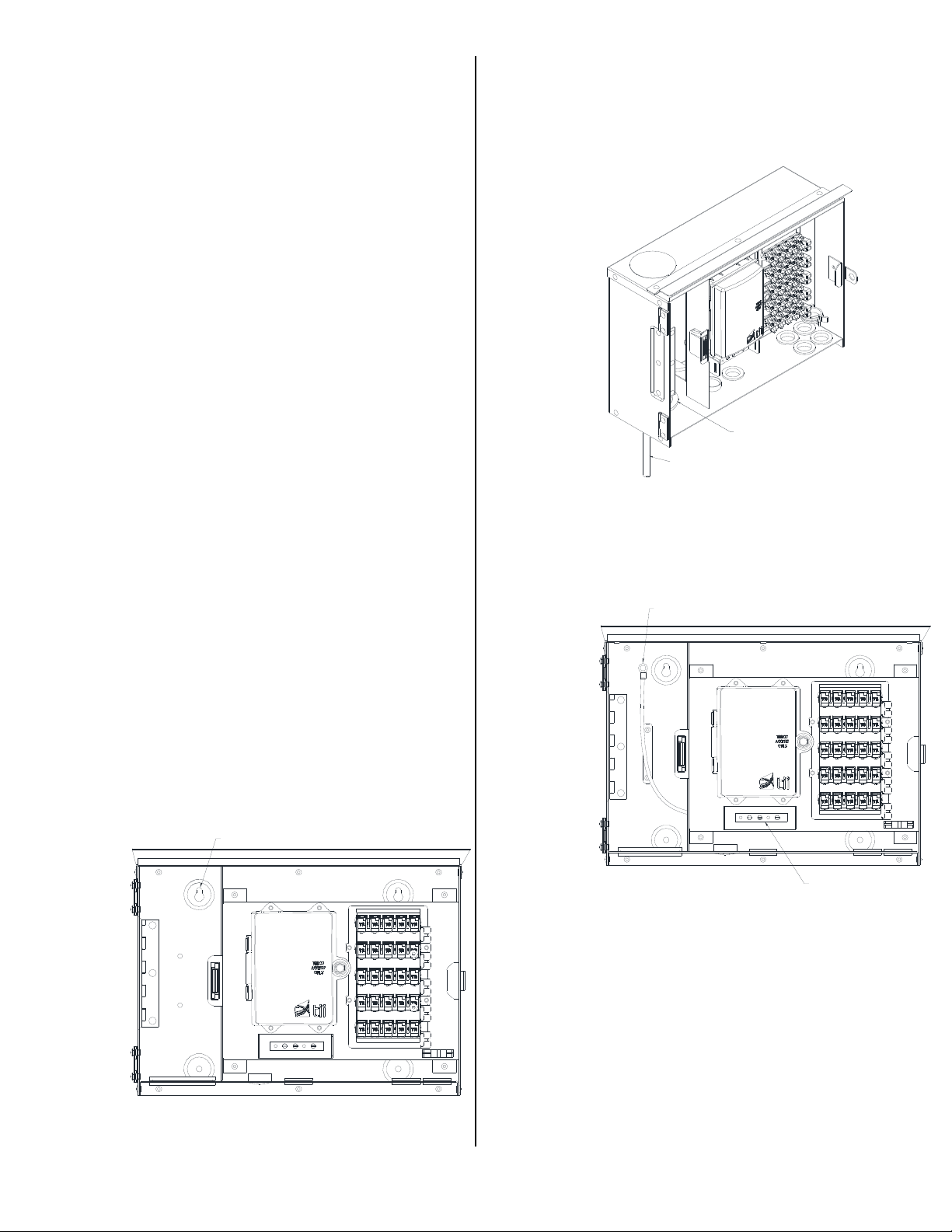
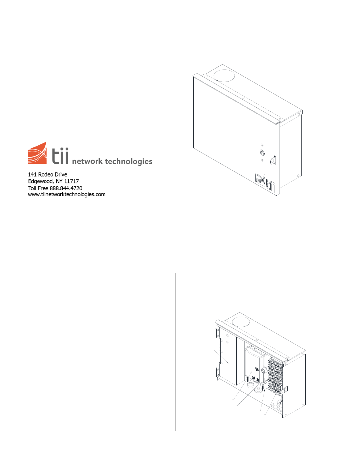
Figure 1
MOUNTING HOLES
CABLE GROMMET
OSP CABLE
6 AWG GROUND WIRE
GROUND BAR
Installation
Use and location selection
Fixed outdoor BET is intended for outdoor use and
should be located:
1. Mount on the suitable vertical surface that is
firm and screw holding power is adequate.
2. Where easily accessible and where
maintenance will not block a passageway.
3. Where there is no risk of severe moisture.
4. With adequate clearance from electric light
fixtures, equipment and power circuits and
where there is no risk of damage by moving
machinery, doors etc.
5. Near a suitable earth ground.
Protector Modules
BET will accept five pin protector modules. Protector
modules must be listed for primary protection per
UL497 in order to maintain the UL listing of the BET.
The BET and Protector Modules shall be installed and
connected to earth ground IAW the instructions
contained herein and the applicable requirements of
the National Electric Code, ANSI/NFPA-70, Article 800
and any applicable local codes.
CAUTION
Risk of Electrical Shock - The BET is not to be
used without associated protector modules.
Installation
3. Insert the OSP cable through the cable
grommet to fit snuggly around the cable.
Terminate a connection with the wires in splice
chamber using MS² or equivalent. To ease
termination of the MS² connector. BET panels
are equipped with MS² connector brackets.
Figure 3
4. Connect 6 AWG ground to the shielding of the
OSP cable using a (user supplied) clamp.
1. Align unit in desired location on a vertical
mounting surface.
2. Affix unit securely with four # 10 wood screws
supplied with the BET.
Figure 4
5. Attached 6 AWG solid copper ground wire to
the ground bar.
6. Install the tip and ring wires of the customer
premises to the appropriate IDC rockers.
7. Plug the 5 pin protector modules into the
corresponding protection fields.
BET units can be vertically stacked. Maximum of 5 100
Figure 2
pair cables cab be passed through the BET.
 Loading...