

Page 1
P/N 92233801 • Rev B• 10/30/2009
Warranty: If this unit fails during the warranty period, contact tii customer service to authorize return. Unit may be returned prepaid.
Model ISB
Intercom System Bypass
Model ISB PLATE
12 Position Panel
Description
1. This Installation Note covers the description
and installation of the TII ISB and ISB PLATE.
The TII ISB is deployed in conjunction with the
TII ISB PLATE panel. The TII ISB is supplied
as an individual module. The ISB PLATE can
accommodate up to 12 TII ISB modules. The
TII ISB has been designed to provide DSL
signal bypass in MDU applications where
POTS lines with DSL signals are required to
interface with intercom systems. The TII ISB
should only be used for indoor applications.
IDC rockers are used to terminate 26-22 AWG
solid wire. Test points are provided to test
signal integrity at input and output IDC’s.
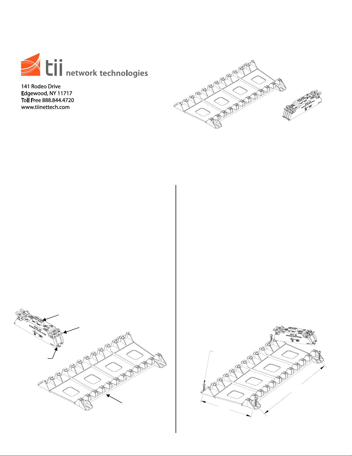
Features
WIRE
GUIDES
TEST
PORTS
IDC ROCKERS
CAN ACCOMMODATE UP
TO 12 ISB MODULES
Installation Note
Installation
1. Locate a suitable flat, dry area to install the
ISB PLATE panel.
NOTE: The ISB modules and the ISB plate must be
located in an restricted Telco personnel access
only area of the building.
2. Mount the ISB PLATE panel with (4) #8 Sheet
Metal Screws (Hardware Not Supplied). Refer
to Figure 1 for ISB PLATE mounting
dimensions. If the ISB PLATE panel is already
installed, identify the position in which the TII
ISB module is to be installed.
3. Holding the module on an angle as shown in
Figure 1, engage the left side fingers under
the catch on the ISB PLATE panel. Slowly
lower the module and align the latch with the
panel and engage module to the panel.
Confirm that the module is securely engaged
to the panel.
(4) #8 SCREWS
6.50
ISB
ISB PLATE
11.75
Figure 1
Page 2
)
4. Lift the Line Input rocker for the Telco service
wires to the full up position. DO NOT strip
wires (See Figures 2 & 3).
5. Insert the Telco service wires into the wire
guides simultaneously until they bottom-out.
While holding wires in position, terminate into
Line Input rocker by lowering to the full down
terminated position (See Figures 2 & 3).
Terminated Rocker
Full Up Position
Wire Guides
Figure 2
6. Lift the From Enter System rocker to its fully
upright position. Insert the enter system output
wires into the From Enter System marked
rocker. While the wires are fully inserted, lower
the rocker fully down to complete the Enter
System Output wire termination (See Figures
2 & 3).
7. Terminate the customer wiring onto the Line
Output rocker on the right side of the module.
Insert wires into the customer rocker holes.
While assuring that the wires are fully inserted
lower the rocker to its fully seated position
(See Figures 2 & 3).
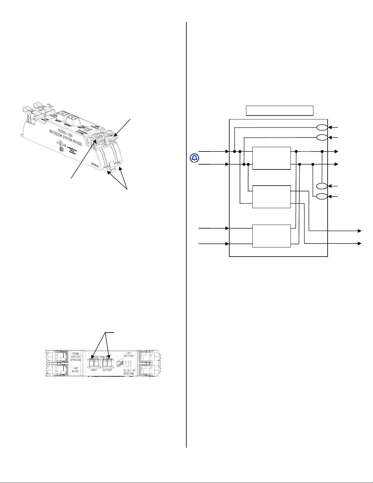
TEST POINTS
Figure 3
9. To keep wire pairs organized, route them
through the molded wire guides (See Figure
2).
10. Connect test clips to input test port and make
sure POTS line dial tone is present. Repeat
testing for the output connections using output
test port.
11. Refer to Figure 4 for the ISB module functional
schematic.
FUNCTIONAL DIAGRAM
TELCO LINE
INPUT (TIP)
TELCO LINE
INPUT (RING)
HIGH PASS
FILTER
(HPF)
LOW PASS
FILTER
(LPF)
FROM ENTER
SYSTEM (TIP)
FROM ENTER
SYSTEM (RING)
LOW PASS
FILTER
(LPF)
Figure 4
INPUT TEST
PORT (TIP)
INPUT TEST
PORT (RING
LINE OUTPUT
OUTPUT TEST
PORT (TIP)
OUTPUT TEST
PORT (RING)
TO ENTER
SYSTEM (TIP)
TO ENTER
SYSTEM (RING)
8. Terminate wire pair serving as input to enter
system at the rocker labeled To Enter System
on the right side of the module. Follow the
procedure described above for the wire pair
termination (See Figures 2 & 3).
 Loading...