

Page 1
P/N 92242001 • Rev A • ECN 14-119 • 5/7/2014
Warranty: If this unit fails during the warranty period, contact tii customer service to authorize return. Unit may be returned prepaid.
Model FDT1 Series
Fiber Distribution Terminal
Installation Note
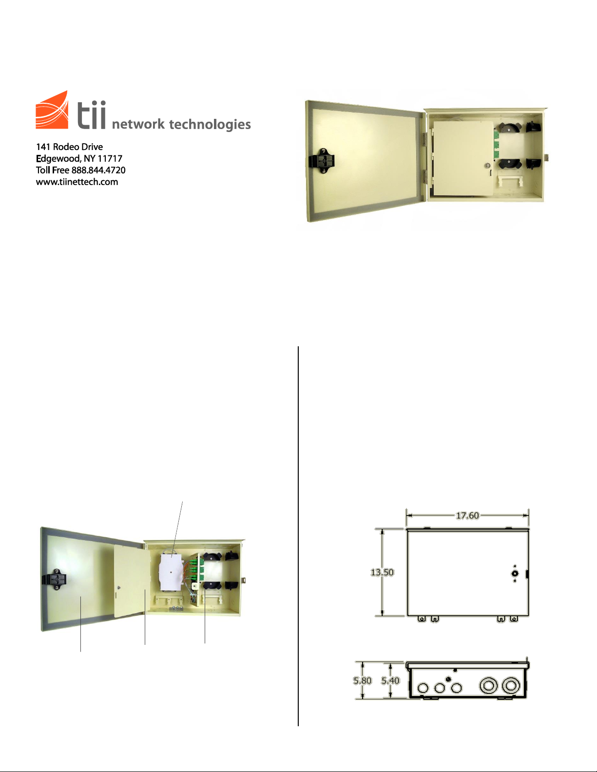
Description
Splice
Compartment
Customer
Drops
Inner Door
Outer Door
Installation
The FDT Series Fiber Distribution Terminals
provide splicing connectivity to the OSP feeder
fiber and a point of demarcation for customer drop
terminations.
Features
Up to 24 fiber drops.
Top, bottom and side 1” and 2” conduit knockouts
Removable and lockable inner and outer doors
Inner door converts to work surface
Optional protective bottom cable entry skirt
The FDT is designed for outdoor or indoor installation.
It can be ordered empty and configured on-site or
factory loaded with adapter plates, pigtails, and splice
trays to reduce installation time.
1. Verify contents and inspect for damage
2. Select installation site:
Vertical wall surface
Easily accessible
Adequate clearance from electric light
fixtures, equipment and power circuits.
Near suitable earth ground
Figure 1
Figure 2
Page 2
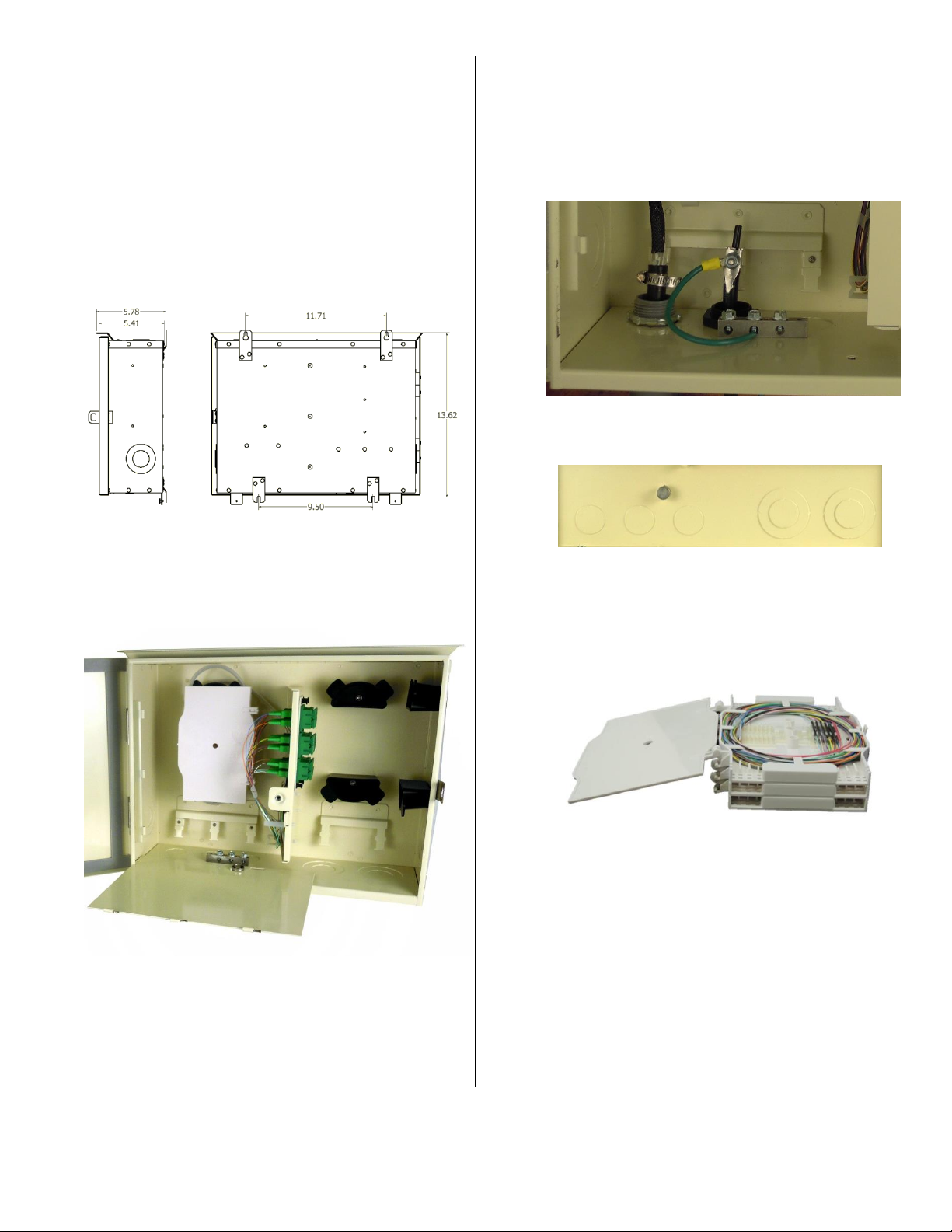
3. Knock out required cable entry conduit ports.
Top – 2 ea combination 1” / 2”
Side – 1 ea combination 1” / 2 “
Bottom – 2 ea combination 1” / 2”
3 ea 1”
4. Trim and install conduit fittings or NPT
compression couplings as needed.
5. Mark and install appropriate wall hanging
hardware and secure unit.
Figure 3
6. The inner door can be used as a work surface
in remote or confined space installations. Lift
the inner door from hinges and use 216 tool to
secure 3/8” bolt to bottom of enclosure.
7. Cut excess feeder cable to length leaving a
minimum of 3 ft. of slack from point of entering
splice bay. Location to perform fusion splicing
will dictate exact length necessary of slack.
Remove protective jacketing material to
expose fiber cable subunits and secure to
cable entry point. Ground and bond armored
or tonable cable using provided ground bar.
Figure 5
8. Ground the FDT enclosure to a suitable earth
ground using the external ground stud.
Figure 6
9. Splice feeder fiber to pigtails using the FST
modular splice tray. The trays are stackable
and have 3 attaching points to secure one tray
to the other. Each tray can splice up to 24
single fusions or 6 mass fusions.
Figure 4
Figure 7
10. Store feeder fibers and pigtail slack in
provided slack management rings.
11. Customer drops are routed from the cable
entry ports to the patch panel and slack is
stored in the provided slack management
rings.
 Loading...