

Page 1
Fiber Optics.
A Division of Tii Network Technologies Inc.
5103 Pegasus Ct., Suite H
Frederick, MD 21704
Contact – 888-844-4720
301-874-4688
Fiber Optics
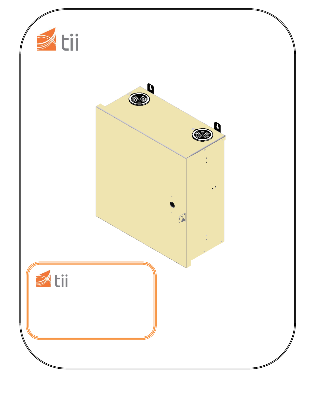
TII FDH1 Indoor Fiber Distribution Cabinet
1 Tii Network Technologies Inc. 2012
Page 2

Copyright © 2012 Tii Network Technologies Inc.
All rights reserved.
Revision History
ISSUE DATE REASON FOR CHANGE
1 3/2012 Original release
TRADEMARK INFORMATION
TII Network Technologies, Tii, Tii (Logo) and Tii Fiber Optics are trademarks.
DISCLAIMER OF LIABILITY
Contents herein are as of the date of publication. Tii Network Technologies Inc. (Tii) reserves the right to
change the contents without prior notice. In no event shall Tii be liable resulting from the loss of data, loss of
use or loss of profits and Tii further disclaims any and all liability for indirect, incidental, special, consequential
or other similar damages. This disclaimer applies to all products, publications, and services during and after
the warranty period.
General Safety Precautions
Warning – Wet conditions increase the potential for an electric shock when installing or
using electrically power equipment. To prevent shock, never install or use electrical equipment in a
wet location or during a lightning storm.
Danger – Do not look into the ends of any optical fiber. Exposure to laser radiation may
result. Do not assume the laser power is turned off or that the fiber is disconnected at the other end.
Caution – Always follow corporate safety practices when handing, striping and preparing
fiber optic cable, fiber shards can be dangerous if they are not disposed of properly. Always wear
proper safety equipment – including safety glasses, gloves etc. Refer to corporate standards when in
doubt.
2 Tii Network Technologies Inc. 2012
Page 3
1. General
1.1. The Tii FDH1 Series is a wall mount fiber distribution hub designed to support patching, splicing and
optical splitting in one unit. The enclosure has 9 adapter panel positions allowing for a wide variety of
patching and splitting combinations. Two compartments separate the network terminations from the
distribution terminations and a single outer door.
1.2. Accommodates 12-48 fiber ports for use in indoor demarcation points and MDU distribution
applications.
1.3. Available with adapters, splice trays and pigtails.
1.4. Door is removable for easy handling and maintenance.
1.5. Multiple bottom cable entry points for ease of cable entry both top and bottom.
1.6. Two splitter module capacity.
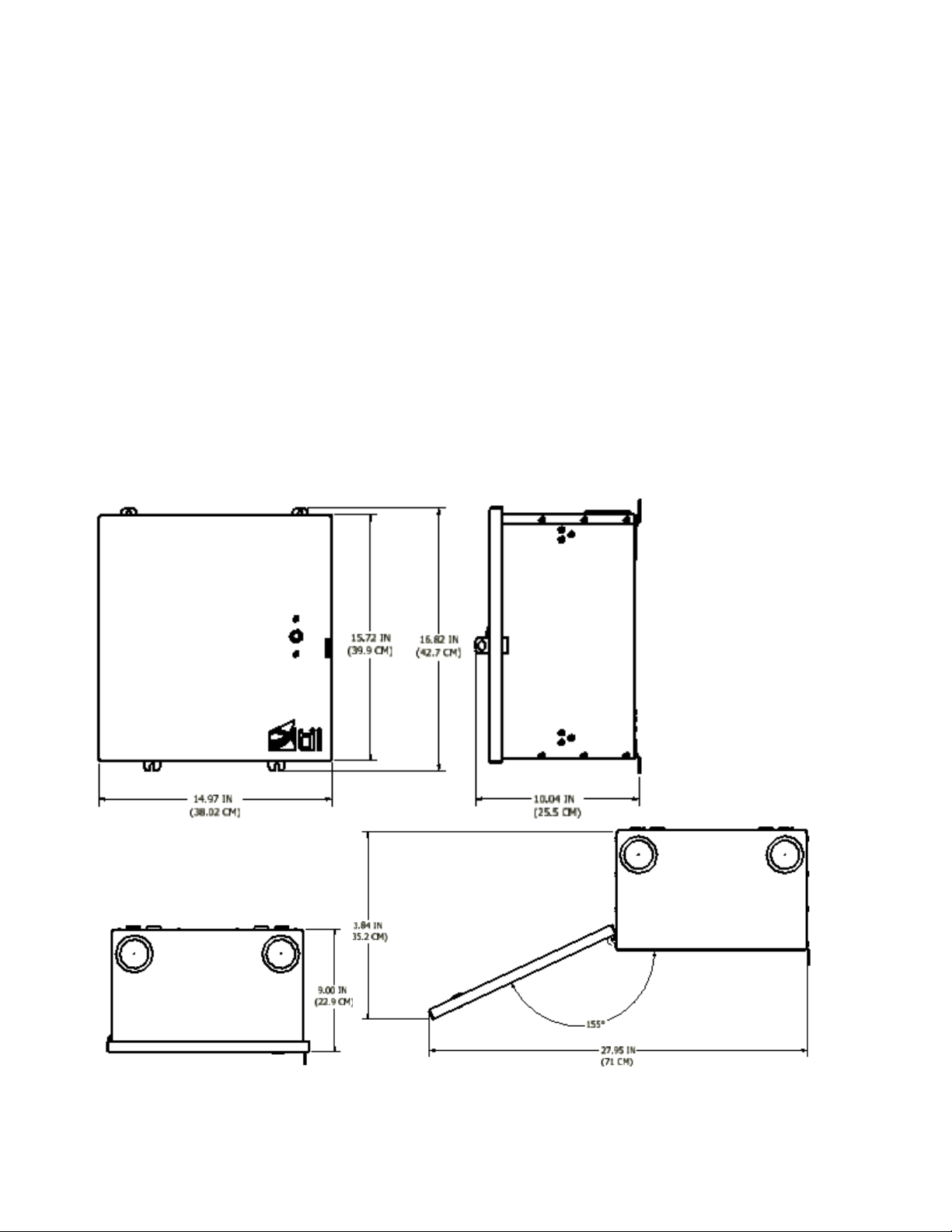
2. Dimensions
3 Tii Network Technologies Inc. 2012
Page 4
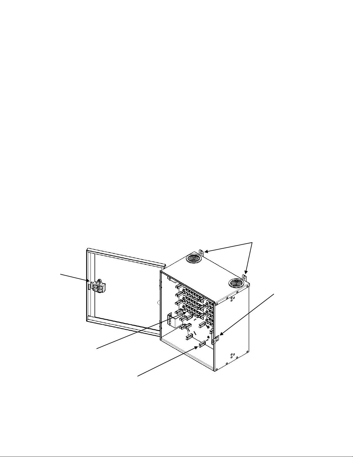
Fiber Routing Guides
Modular LGX Adapter plates (6,8 or 12)
Padlock Hasp
Slam-latch
Mounting Ears
3. Warranty
3.1. See TII Warranty. If this unit fails during the warranty period, the factory should be requested to
authorize return. Return the unit prepaid. Units that fail due to normal wear or abuse should be
discarded.
4. All cabinet versions.
4.1. Modular LGX bulkhead adapters - for interconnection between feeder and distribution fibers.
4.2. Slack Storage - The FDH1 is designed to allow for storage of pre-terminated 12F SST drop cable inside
the unit with tie-downs to secure the cable.
4.3. Output Fiber Management – Provides a method of routing fibers to the LGX adapter plates.
4.4. Splitter Compartment – Provides a location to mount one or two 1x32 splitters modules. Secured via
Velcro straps.
4.5. Interior Grounding Lug – Provides a bonding and grounding point for all dielectric fiber cables.
4.6. Entry Ports – Equipped with Top and Bottom entry ports to allow for use of input/output cable
configurations.
4.7. Removable Outer Door – To allow for easy installation in confined spaces.
4 Tii Network Technologies Inc. 2012
FIGURE 1. Basic Layout.
Page 5

Fiber Slack Storage
Top Entry Ports
FIGURE 1a. Basic Layout
5. FDH1 Cabinet
5.1. The Tii FDH1 Series Cabinet can be configured in three (3) versions including an all patch version, a
patch and splice version and a PON Version.
5.2. Figures 1 and 1a shows the general features of the FDH1.
5.3. The all patch version, shown in figures 1 & 1a, is equipped with LGX plates modular adapter plates (in
6, 8 or 12 adapters) for either24, 32 or 48 patch only configurations. This version assumes the use of
pre-stubbed drops with fan-out or field installable connectors on both input and output.
5.4. The unit also is equipped with 1 single LGX modular adapter plate for pass through fiber (where
applicable).
6. Patch and Splice
6.1. Shown in figure 2, is equipped with LGX plates modular adapter plates (in 6, 8 or 12 adapters) for
either24, 32 or 48 patch configurations and is equipped with up to four (4) splice trays.
6.2. One (1) to accommodate the feeder fiber and three (3) to accommodate splicing of the distribution
fibers.
6.3. Optionally the LGX adapters may be ordered with 6, 8 or 12 fiber pigtail assemblies, per-installed into
the spice trays. The pigtails may also be purchased separately.
5 Tii Network Technologies Inc. 2012
Page 6

Multiple Entry Ports
Splice Trays
12 Fiber Feeder- LGX Adaptor Plate
4 – 12 LGX adapter plates for distribution fibers
4 Blank LGX plates for 1x32 splitter parking lot
Fiber Routing Guides
FIGURE 2. Patch and Splice.
FIGURE 3. Splice tray layout
6 Tii Network Technologies Inc. 2012
Page 7

Splitter Module Retainer
1 x 12 Feeder fiber module
4 – 1x 8 LGX Distribution Modules
4 – 1 x 8 LGX Splitter Parking Lot
7. PON Version.
7.1. Figure 4 shows the PON version which is a 1x 32 configuration with 1 X 12 fiber pass through and 4 x
8 LGX (32) modules distribution with an additional 4 X 8 LGX (32) modules for a parking lot. Included
is a 1 x 32 PON splitter.
7.2. Pigtails from the splitter are routed across the front of the inside door while the distribution fiber are
either splice in the splice trays and connected via factory installed pigtails to the modules or via field
installed mechanical connectors.
FIGURE 4. PON Version
FIGURE 5. PON Version- Layout with labeling.
7 Tii Network Technologies Inc. 2012
Page 8

FDH Label
8. Labeling
8.1. Depending upon configuration, the FDH 1 adapter plates will be labeled according to layout. Figure 5,
shows F – Designating 1-12 Feeder fibers, D – designating 1-32 Distribution fibers and PL- Designating
1-32 Splitter Parking Lot.
8.2. Figure 6 shows the standard door label for the recording of Feeder and distribution fiber (Subscriber
Termination Field).
8.3. The surface allows for field recording of the designated fiber and subscriber terminations.
FIGURE 6.
8 Tii Network Technologies Inc. 2012
Page 9

9. Installation Guide – General
9.1. Recommended Tools
9.1.1. Portable work table
9.1.2. Cleaning supplies Squeeky Kleen, alcohol, wipes
9.1.3. Jacket ring tool (or flat drop stripper)
9.1.4. Kevlar sheers
9.1.5. Buffer scribe tool
9.1.6. Strip tool 3mm, 900um, 250um
9.1.7. splice sleeves
9.1.8. Fusion splicer & cleaver set
9.1.9. OTDR, OLTS, or VFL
9.1.10. Screw gun & appropriate screws for install location (wood, metal, concrete etc.)
9.2. Summary of Steps
9.2.1. Wall mount
9.2.2. Install cables
9.2.3. Work area setup
9.2.4. Terminate
9.2.5. Patch
9.2.6. Patch & splice
9.2.7. PON splitter
9.2.8. Store slack
9.2.9. Test
9.3. Mounting
9.3.1. Install 4’x4’x¾” plywood backboard to most secure points practical using appropriate hardware
9.3.2. Concrete block
9.3.3. Brick
9.3.4. Structural studs
9.3.5. Secure FDH to backboard using provided 4 point attaching brackets using ½” wood screws
typically centered or as appropriate to install site.
9 Tii Network Technologies Inc. 2012
Page 10

9.4. Install Cables
9.4.1. Overall lengths will be dependent on work station location to the FDH
9.4.2. The FDH can store approximately 20 ft of feeder cable and home run MDU drops.
9.4.3. Secure cables to provided top and bottom cable entry tie down points using zip ties or hose
clamps as appropriate.
9.4.4. Ground and bond any armored cable to provided ground lugs
9.4.5. Pre-measure and cut to length cables to termination points (dependent to configuration – patch,
patch & splice or PON).
9.5. Work Area Setup
9.5.1. Set a portable table as close to final installation site as feasible and stage items.
9.5.2. Hand tools.
9.5.3. Splicer & Cleaver (if required).
9.5.4. Cleaning supplies.
9.5.5. If configured remove pigtail from slack storage up to breakout, ensure pigtails reach workspace
or remove adapter plates if necessary.
10 Tii Network Technologies Inc. 2012
Page 11

9.6. Prepare Cables
9.6.1. Allow minimum 10 ft of slack cable to route into FDH (site dependent) excess to be cut off.
9.6.2. Remove jacket and armor 2” within entry point.
9.6.3. Secure drop and feeder cables to provided “T” clamps using zip-ties or hose clamps as
appropriate.
9.6.4. Excess cable should be pre-measures and allow enough slack to reach work area and be stored
neatly in FHD, cut to length needed for configuration.
9.7. Patch
9.7.1. Install each MDU home run drop cable to rear patch panel, label as required.
9.7.2. Install pre-terminated trunks or field install feeder cables front of patch panel, inactive fibers
9.7.3. Dress, route and secure feeder & MDU drops to provided cable management clips
stored in parking lot.
11 Tii Network Technologies Inc. 2012
Page 12

9.8. Patch & Splice
9.8.1. Prepare workspace for splicing.
9.8.2. Stage splice tray near splicer.
9.8.3. Splice each feeder fiber.
9.8.4. Place splice fiber in trays splice chip holders.
9.8.5. Dress and secure buffer and pigtails to splice tray using zip-ties.
9.8.6. Install up to 4 splice trays and store slack in provided cable management brackets.
9.8.7. Route pigtails to front side of panel, stage fibers in parking lot and secure slack using fiber
management clips.
9.8.8. Activate MDU connections by moving from parking lot to MDU dwelling ports as required.
12 Tii Network Technologies Inc. 2012
Page 13

9.9. Typical PON
9.9.1. Install each MDU home run drop cable to rear patch panel, label as required.
9.9.2. Top most adapter plate for feeder cable high power pass-through and splitter connections.
9.9.3. Splice feeder fiber(s), field terminate or install stub as required rear side of top adapter plate.
9.9.4. Install splitter housing to rear panel using alignment stud and Velcro.
9.9.5. Route splitter legs to front side patch panel.
9.9.6. Install splitter input (blue strand) to top adapter plate feeder cable.
9.9.7. Install splitter outputs (yellow strands) to parking lot.
9.9.8. Activate MDU connections by moving from parking lot to dwelling ports as required.
13 Tii Network Technologies Inc. 2012
Page 14

9.10. Slack Storage
9.10.1. Coil buffer tube strands around splice tray and store slack in cable management brackets.
9.10.2. Secure buffer tubes and pigtails to cable management clamps using supplied Velcro and or
zip-ties.
9.10.3. Secure fan-out kits.
9.10.4. Install splice tray securing grommet and wing nut.
9.10.5. Dress and secure slack cable.
9.11. Test
9.11.1. Clean and inspect any ferrule prior to mating, contamination can damage ferrule end face.
9.11.2. Typical insertion loss of factory terminated pigtails and fusion splice should be expected to
be 0.25 – 0.5 Db.
9.11.3. Typical reflectance -55 dB UPC.
9.11.4. Typical reflectance -65 dB APC.
9.12. Close unit and secure.
14 Tii Network Technologies Inc. 2012
 Loading...