

Page 1
P/N 92209201 • Rev H• 8/28/2008
Warranty: If this unit fails during the warranty period, contact tii customer service to authorize return. Unit may be returned prepaid.
Model AD-SERIES Angle Driver Module with Surge Protection
ADX-SERIES Angle Driver Module without Surge Protection
Installation Note
Description
Installation
1. The AD-Series & ADX- Series Station
Protector modules may be installed in a wide
variety of station protector and network
interface housings.
2. The AD-Series & ADX- Series Station
Protector Modules provides one upper and
two lower ports per line for ease of wiring and
termination. It is equipped with a universal
grounding and mounting tab.
3. All ports utilize tool-less IDC rockers. The
upper ports accept 22-26 awg wire, the lower
ports terminate 18.5 ”F” drop - 24 awg wire.
Both ports are terminated by the driver bolt
mechanism.
4. The AD-Series & ADX- Series modules are
equipped with integral sealed test points for
ease of troubleshooting.
NOTE
National Electric Code Requirement. The
protector shall be installed per National
Electric Code ANSI/NFPA 70, Article
800, Section C, and shall meet all
applicable local safety codes.
These modules shall be installed in NID
enclosures evaluated to the requirement
of UL497.
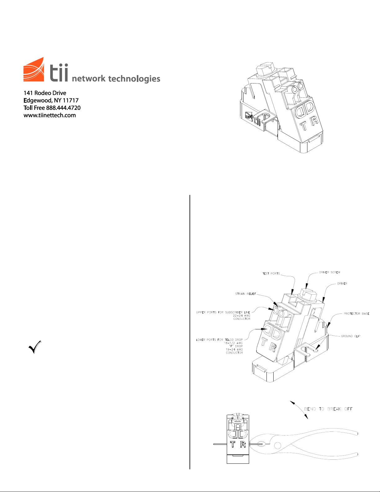
1. The Angle Driver is delivered with a universal
grounding and mounting tab (See Figure 1). If
installing a new module into a NID, break
away the unwanted ground tab from the
module using a pair of pliers and discard (See
Figure 2). Install module on desired NID
ground post and secure with washer and nut.
Figure 1
Figure 2
Page 2
Wiring
IDC
SUBSCRIBER
CONNECTION
WIRE
TELCO
WIRE
DRIVE SCREW
Testing
1. The two upper ports of the Angle Driver are
intended to terminate subscriber (customer)
wires. Telco drop (feeder) wires must be
terminated in the two lower ports of the Angle
Driver.
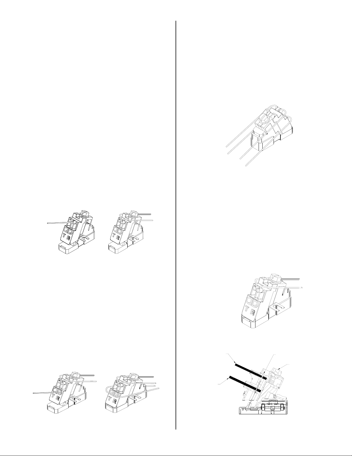
2. Upper Port Subscriber Connections (See
Figure 3) Subscriber terminations are already
made at the factory. If it is necessary to reterminate a subscriber wire, do so as follows:
3. Do not strip wire insulation. Make certain wire
ends are cut flush with insulation.
4. Unscrew Angle Driver screw to the full upright
position.
5. Fully insert the two subscriber wires into their
respective tip and ring (color-coded) ports.
6. Insert while holding the two subscriber
connection wires in place. Ensure wires are
fully inserted beyond the IDC connector
(See Figure 7). Tighten Drive Screw to the full
down position. Pull on wires to ensure
proper connection. Wires should remain
securely in place.
7. Dress the wires through the strain relief slots
to hold them in place (See Figure 3).
Figure 3
Lower Port Telco Connections
(See Figure 4)
1. Feeder and subscriber wires must be
segregated between the upper and lower ports
to facilitate isolation testing (See Figure 5).
Upper and Lower Port Connected
1. With Driver in the fully closed position, insert
test clips into tip/ring test port access holes
located at top of driver. Perform customary
tests.
Figure 5
Testing Subscriber Connections
(See Figure 6)
1. Loosen drive screw so driver is in the full
upright position.
2. Remove telco wires from lower ports of driver.
3. Tighten drive screw so driver is in the full
down position.
4. With Driver in the fully closed position, insert
test clips into tip/ring test port access holes
located at top of driver. Perform customary
tests.
1. Do not strip wire insulation. Make certain wire
ends are cut flush with insulation.
2. Unscrew Angle Driver screw to full upright
position.
3. Fully insert the two feeder (telco) wires into
their respective tip and ring (color-coded)
ports. Ensure wires are fully inserted
beyond the IDC connector (See Figure 7).
4. While holding the two telco wires in place,
tighten Drive Screw to full down position. Pull
on wires to ensure proper connection.
Wires should remain securely in place.
Figure 4
Figure 6
Figure 7
 Loading...