

Page 1
141 Rodeo Drive tii 97C
Edgewood, NY 11717 ADSL POTS Splitter Module
Customer Service/Sales 888-844-4720 Rev C 07/09
INSTALLATION NOTE
1. Description
The TII 97C ADSL POTS Splitter Module is designed for use at
the subscriber premises in a CAC
module houses electronics known as a “POTS Splitter”. The
POTS Splitter allows both voice and data signals to travel over
the telephone line. This device splits the combined signal to
provide separate outputs for both phone and data. The ADSL
POTS Splitter Module must be used along with a Protected
Customer Bridge Module (PCBM) provided in the Outdoor
Network Interface Device. The TII 97C ADSL POTS Splitter
Module and the PCBM’s are interconnected to provide the
subscriber output screw terminals for wiring both voice and
data.
2. Accessing the Network Interface Device (NID)
Open the outer cover on the Outdoor NID by loosening the
customer access screw.
3. Installing the TII 97C ADSL POTS Splitter Module into
the NI-2000 Series Footprint NID
Install the ADSL POTS Splitter Module into the NID by snapping
it into the appropriate line module position (see Figure 2).
• Place the lower flange on the module under the base latch.
• Rotate the free side of the module down into the base
ground bar.
4. Interconnecting the ADSL POTS Splitter Module with
the PCBM
• See inside door of NID for warnings before wiring.
• Remove existing subscriber voice wires from the PCBM
and connect them to the screw terminals on the ADSL
POTS Splitter Module (Tip to green, Ring to red).
®
NI-2000 Series NID. This
Figure 2
Telco Feed Wires
• Connect the line-in terminals of the TII 97C to the screw
terminals on the PCBM (Tip to green, Ring to red) (see
Figure 3).
• Dress any excess wire along the side of the base.
After interconnecting the modules: The output for DATA
wiring is the screw terminals on the PCBM, and the output for
VOICE wiring is the two screw terminals on top of the ADSL
POTS Splitter Module.
5. Wiring for Voice and Data
Grommet Preparations: If routing additional wires through
the rubber grommet located at the bottom of the unit, punch a
small hole in the grommet. Do not break through the edge of
the grommet. Doing so may compromise the grommet’s
holding ability.
6. Subscriber Wiring
• Route wires through the grommet located at the bottom
of the unit and dress to the appropriate module(s).
• Dress any excess wire along the side of the base.
DATA Wiring: Connect the subscriber DATA wires to the
screw terminals on the PCBM (Tip to green, Ring to red) (see
Figure 3).
VOICE Wiring: Connect the subscriber VOICE wires to the
screw terminals on the ADSL POTS Splitter Module (Tip to
green, Ring to red).
7. Wiring to Screw Terminals
• Strip conductor wires back approximately ½ inch.
• Wrap the bare wire around the screw terminal between
two washers. Do not overlap wire on the screws.
• Cut off any excess wire after tightening the screw
terminal.
8. Securing the NID Unit
Make sure the wire entry grommet is completely seated into
position in the base. Tighten the customer access screw to
secure the cover.
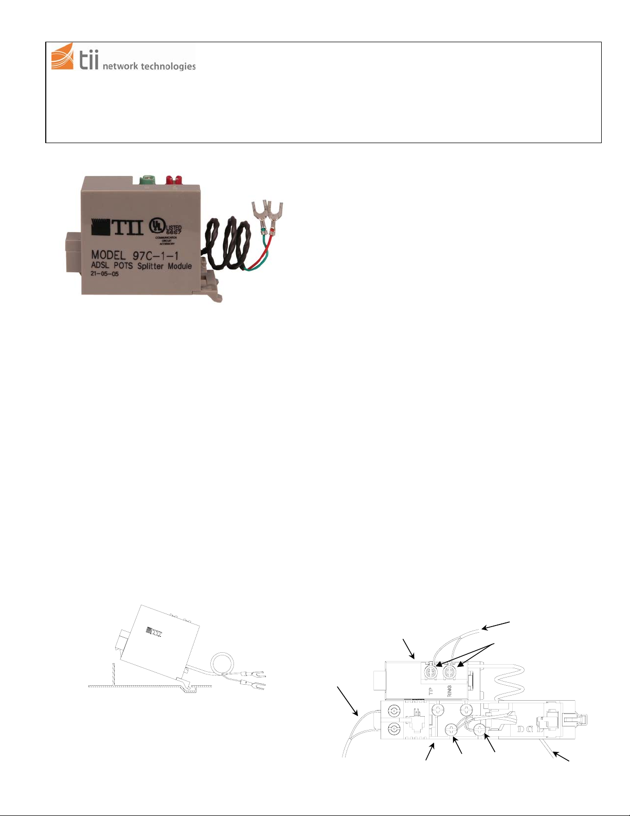
TII 97C POTS Splitter
Protected Customer
Bridge Module (PCBM)
Shown in the Open Position
Tip/Grn Ring/Red
Figure 3
Subscriber Voice Wires
Voice Screw Terminal Connections
Subscriber Data
Wires (To Modem)
TII P/N: 92217401
 Loading...