

Page 1
P/N 92212201 • Rev B• 11/6/2008
Warranty: If this unit fails during the warranty period, contact tii customer service to authorize return. Unit may be returned prepaid.
Model 97
ADSL POTS Splitter Module
Installation Note
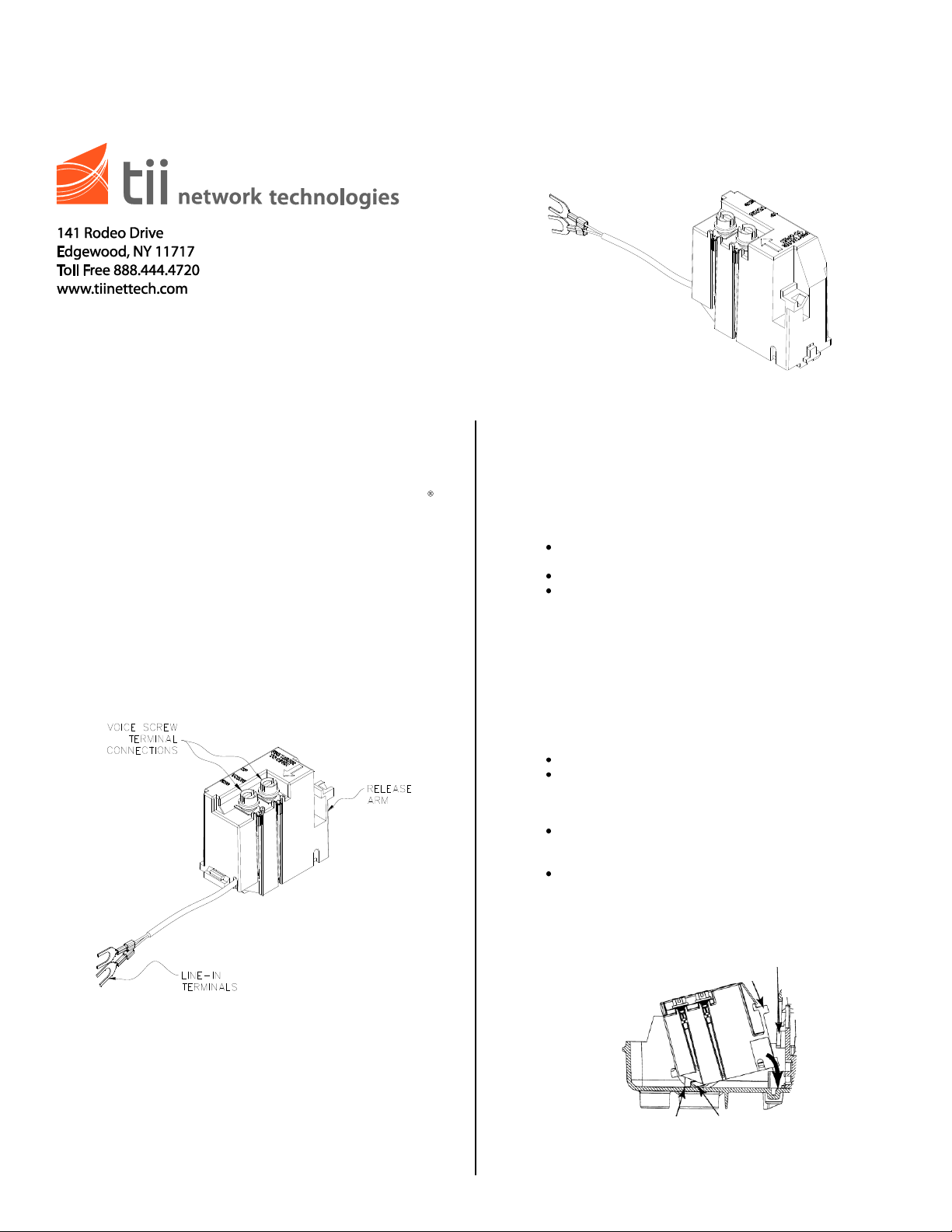
DESCRIPTION
Center Wall
Latch
Release Arm
Base Latch
Lower Flange
INSTALLATION
1. The TII 97 ADSL POTS Splitter Module (Figure 1) is
designed for use at the subscriber premises in a TII
3600/3700 Network Interface Device (NID) and a CAC
7600 NID (using a TII 9A Adapter). This module houses
electronics known as a “POTS Splitter”. The POTS
Splitter allows both voice and data signals to travel over
the telephone line. This device splits the combined signal
to provide separate outputs for both phone and data. The
ADSL POTS Splitter Module must be used along with a
Standard POTS Customer Bridge Module (CBM) provided
in the Outdoor Network Interface Device. The TII 97
ADSL POTS Splitter Module and the Standard POTS
CBM’s are interconnected to provide the subscriber output
screw terminals for wiring both voice and data.
FEATURES
Figure 1
1. Installing the 97 ADSL POTS Splitter Module Into the
3600/3700: Open the outer cover on the Outdoor NID by
loosening the customer access screw. Install the ADSL
POTS Splitter Module into the NID by snapping it into the
appropriate line module position (see Figure 2).
Place the lower flange on the module under the base
latch.
Rotate the free side of the module down into the base.
Snap the release arm on the module under the latch on
the center wall of the unit.
2. Installing the 97 ADSL POTS Splitter Module into
CAC® 7600 Footprint NID: Install the ADSL POTS
Splitter Module in the TII 9A adapter by snapping it onto
the adapter (see Figure 3). This assembly will then fit into
any one of the CBM module positions in the NID by
snapping it into the base.
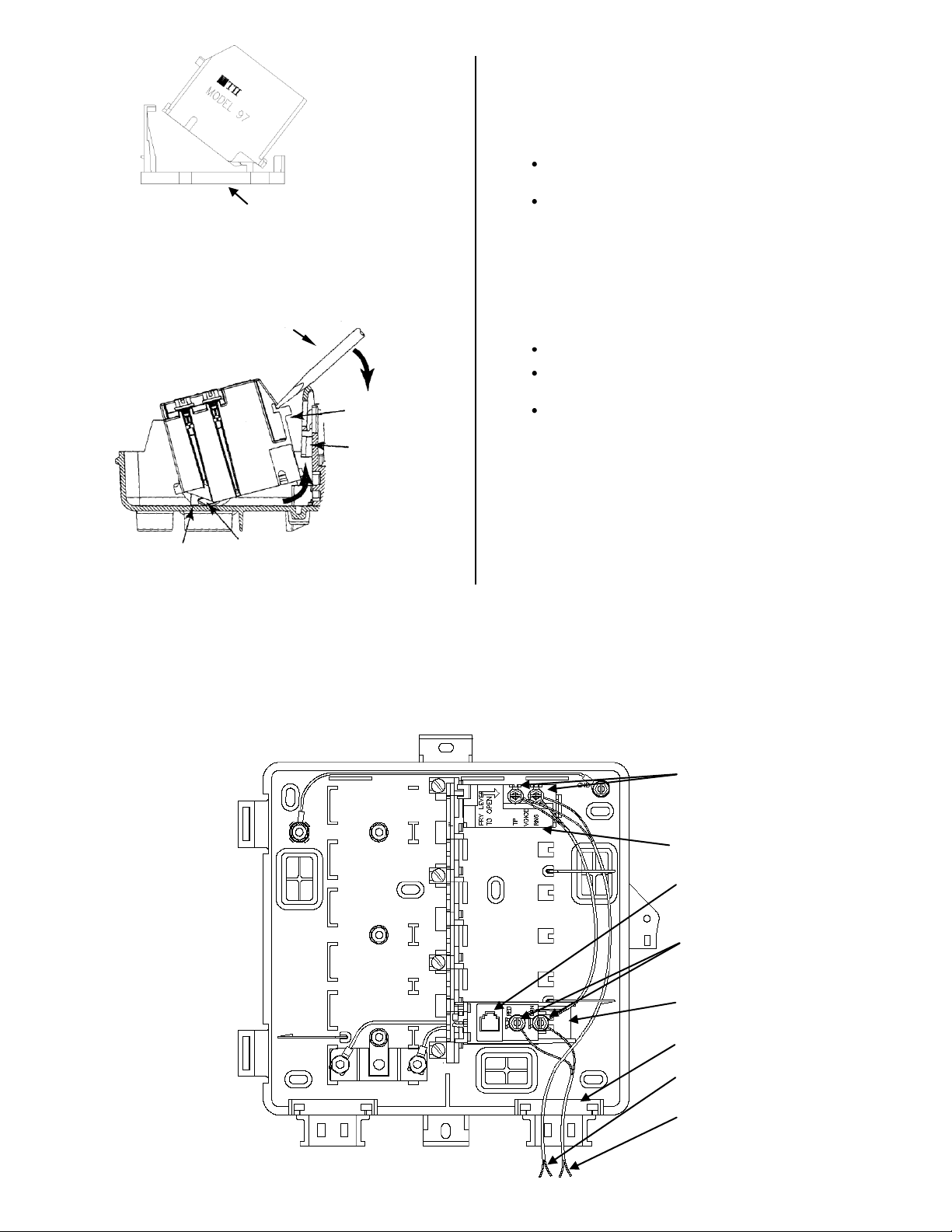
3. Interconnecting the ADSL POTS Splitter Module with
the Customer Bridge Module:
See inside door of NID for warnings before wiring.
Remove existing subscriber voice wires from the standard
POTS CBM and connect them to the screw terminals on
the ADSL POTS Splitter Module (Tip to green, Ring to
red).
Connect the line-in terminals of the 97 to the screw
terminals on the standard POTS CBM (Tip to green, Ring
to red) (see Figure 5).
Dress any excess wire along the side of the base.
4. After interconnecting the modules: The output for
DATA wiring is the screw terminal on the standard POTS
CBM, and the output for VOICE wiring are the two screw
terminals on top of the ADSL POTS Splitter Module.
Figure 2
Page 2
Rubber Grommet
Lower Flange
Base Flange
Screwdriver
Release Arm
Center Wall
Latch
TII 9A Adapter
RJ-11 test Auto-Jack
(for testing only)
TII 97 POTS Splitter
Voice Screw
Terminal
Connections
Data Screw Terminal
Connections
Standard POTS Customer
Bridge Module
Subscriber Voice Wires
Subscriber Data Wires (To
Modem)
Figure 3
5. Wiring for Voice and Data Grommet Preparations: If
routing additional wires through the rubber grommet located
at the bottom of the unit, punch a small hole in the grommet.
Do not break through the edge of the grommet. Doing so
may compromise the grommet’s holding ability.
6. Subscriber Wiring:
Route wires through the grommet located at the bottom of
the unit and dress up to the appropriate module(s).
Dress any excess wire along the sides of the base.
DATA Wiring: Connect the subscriber DATA wires to the
screw terminals on the Standard POTS CBM (Tip to green,
Ring to red) (see Figure 5).
VOICE Wiring: Connect the subscriber VOICE wires to the
screw terminals on the ADSL POTS Splitter Module (Tip to
green, Ring to red).
7. Wiring to Screw Terminals:
Strip conductor wires back approximately ½ inch.
Wrap the base wire around the screw terminal between two
washers. So not overlap wire on the screws.
Cut off any excess wire after tightening the screw terminal.
8. Securing the NID Unit: Make sure the wire entrygrommet is
completely seated into position in the base. Tighten the
customer access screw to secure the cover.
Figure 4
Figure 5
 Loading...