

Page 1
P/N 92215901 • Rev C• 3/3/2008
Warranty: If this unit fails during the warranty period, contact tii customer service to authorize return. Unit may be returned prepaid.
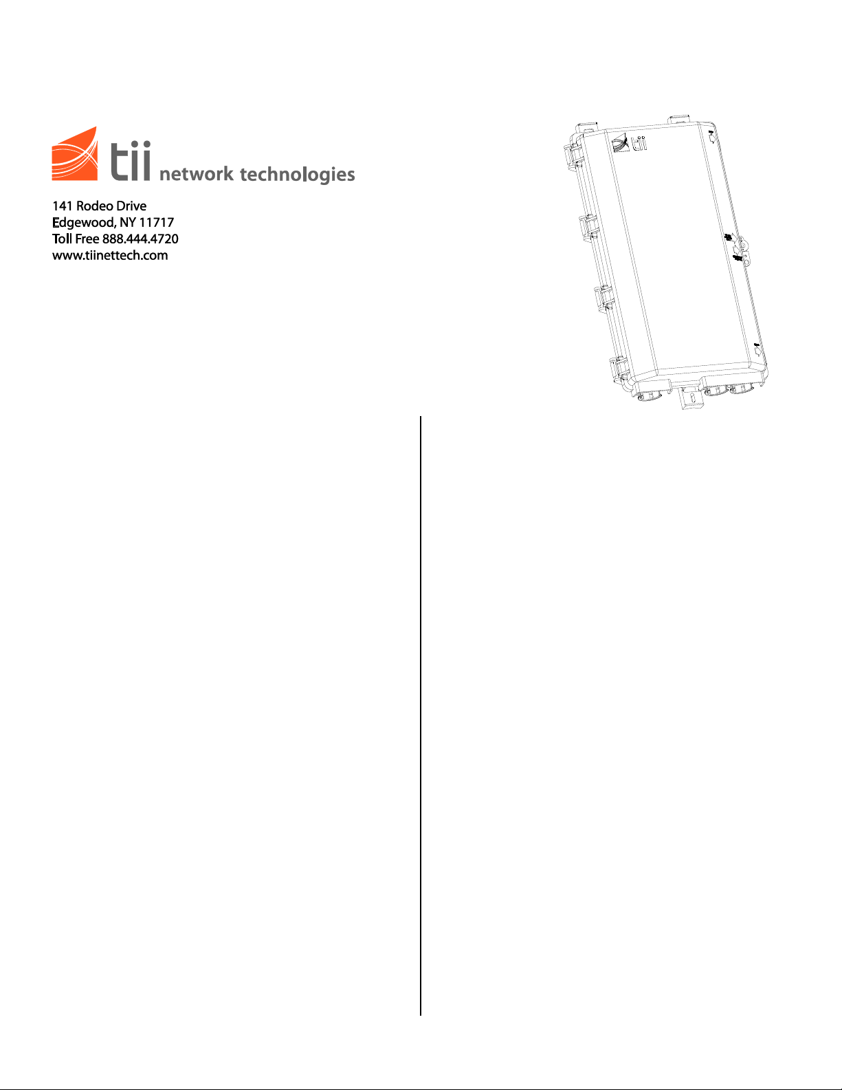
Model 9600
Outdoor 12-Line Broadband NID
Installation Note
Description
Installation
1. This installation note provides the description
and installation steps for the tii 9600 Outdoor
Network Interface. This product is designed
to combine station electronics and network
interface within a single housing.
2. The unit is furnished complete with housing,
protector module(s), RJ-11 jack, customer
wiring bridge(s) for one to twelve lines and
customer instructions.
3. The housing is constructed from rugged heat
and solvent resistant UV stabilized materials.
4. The tii 9600 Outdoor Network Interface is
furnished complete and requires no special
tools for installation or maintenance, except if
ordered with optional pin-in-head security
screw.
5. The unit may be ordered with protection
modules or less protection modules, and may
be ordered with customer wiring bridges for
one to twelve lines.
6. The tii 9600 is provided with two separate side
hinged doors. The outer door has provision
for a padlock. The inner door is held closed
with a recessed hex head security screw to
prevent unauthorized access.
7. tii’s 9600 Outdoor Network Interface can be
fitted with numerous types of protector
modules (see data sheet for tii 9600 Outdoor
Network Interface).
1. External mounting ears are provided for
exterior mounting. Mount the 9600 to the wall
using the appropriate hardware and methods.
2. Thread the protector ground wire through the
lower left hand grommet in the base of the unit
and connect it to the ground stud.
3. Run and connect the ground wire to an
approved ground making the run as short and
straight as possible.
4. Thread the drop wire through the same
grommet and connect it to the tip and ring
ports of gel-filled protector module.
5. If a second line is being installed at this time,
repeat step 4.
6. Secure the incoming drop wire and/or riser
tube with a tie wrap or clamp.
7. Close the telco door and tighten the security
screw until it is snug.
8. Feed the station wire through the lower right
hand grommet in the base of the unit and
terminate the tip and ring on the appropriate
binding posts of the customer bridge module
for Line 1.
9. Repeat step 8 if additional lines are being
installed.
10. Inspect work for shorts, grounds and broken
wires.
11. Close and snap secure the customer bridge
module cover, making certain that it is properly
seated, then close the outer door and secure it
by tightening the screw.
 Loading...