

Page 1
P/N 92233001 • Rev A• 1/20/2009
Warranty: If this unit fails during the warranty period, contact tii customer service to authorize return. Unit may be returned prepaid.
141 Rodeo Drive
Edgewood, NY 11717
Toll Free 888.444.4720
www.tiinettech.com
Model 95S-2-00-0
Sealed Subscriber Bridge
Module with RJ-45 Test Receptacle
Installation Note
Description
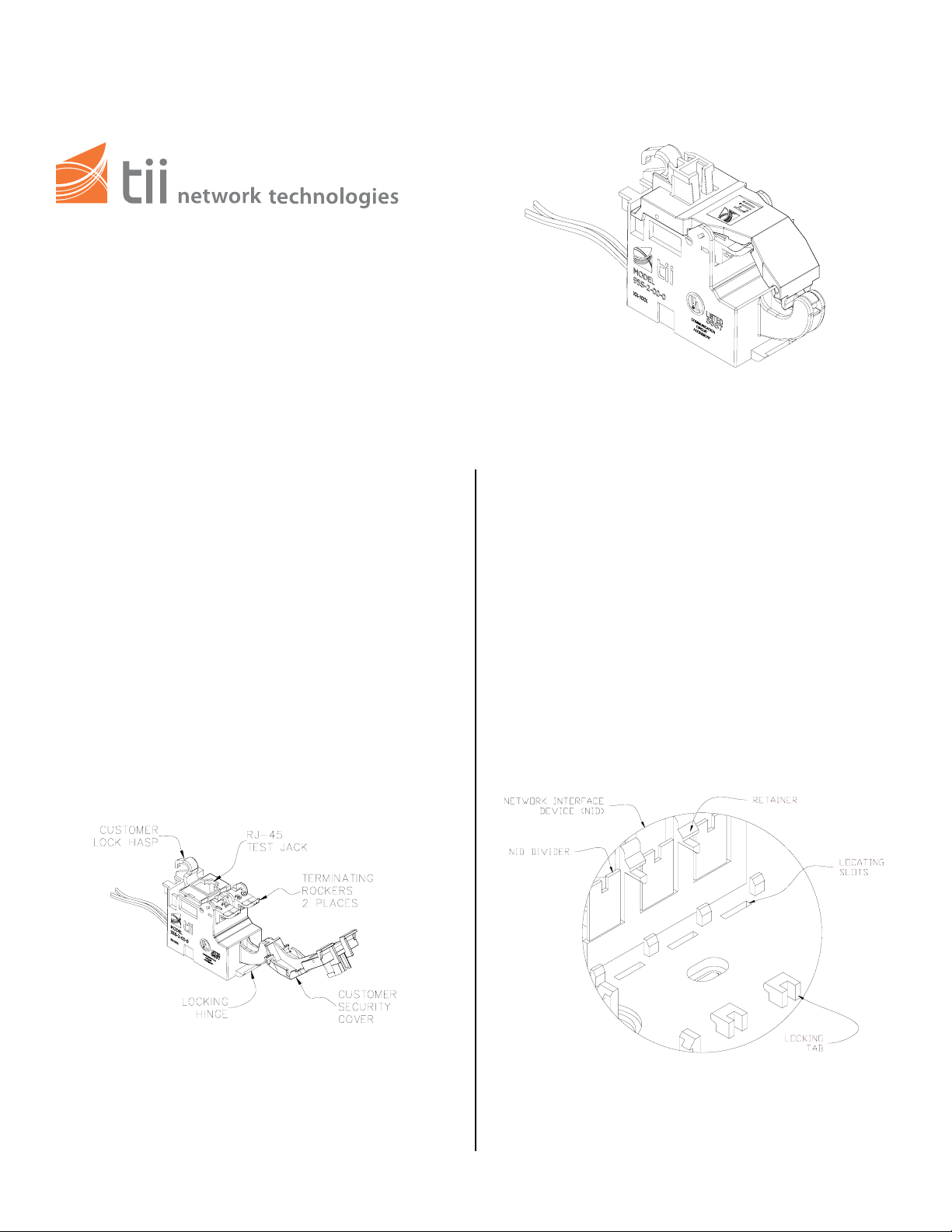
1. The tii 95S-2-00-0 Sealed Subscriber Bridge
Module with RJ-45 Test Receptacle maintains
a constant direct connection between
customer and central office service provider.
The Bridge is equipped with a test jack and
IDC terminations (see figure 1). The test jack
is provided as an access for test equipment to
assure a signal is being received and
transmitted properly.
Features
Installation
1. Hold the Bridge with the cover pivot side on
right.
2. Lower the pivot side edge inside the
designated installation cavity.
3. Engage the right end ledge under the locking
tab. (see figure 2)
4. Push the left side end down until the latch
snaps closed.
Figure 1
Figure 2
Page 2
Wiring
1. The receive and transmit pairs are connected
to the Bridge. Customer has the option of
installing a #10 Master lock around the
customer lock hasp (see figure 1).
2. Do not strip wire insulation from wires to be
terminated to Bridge.
3. Dress terminating wires (to protector) over NID
divider (see figure 2).
4. Open customer security cover on Bridge.
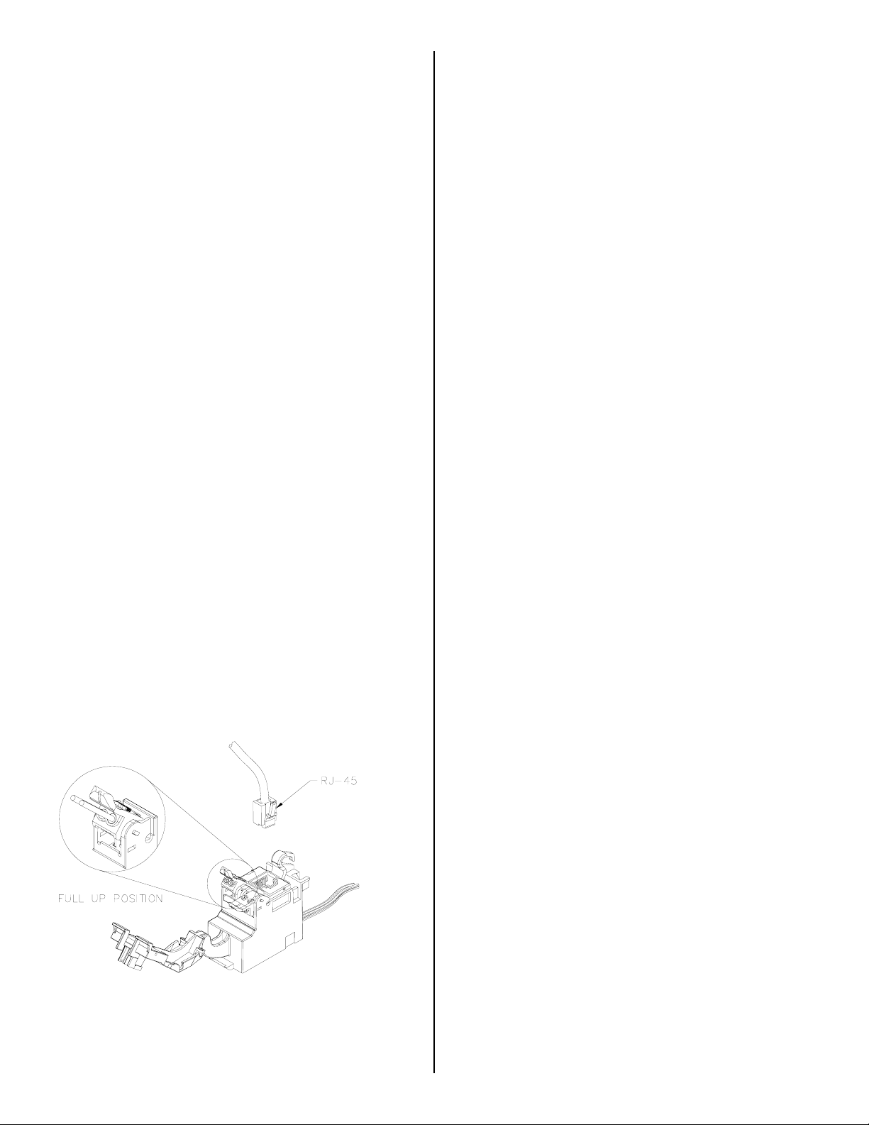
5. Lift both Bridge rockers to the full up position
as shown (see figure 3).
6. Dress wires around security cover.
7. Hold the customer receive pair wires between
thumb and index finger (approx 1/8”
separation between wires).
NOTE: Wires should be aligned to the
corresponding holes.
Signal Testing
1. Open customer security cover.
2. Using a portable data test set, insert dataline RJ-45 plug
into customer test jack (see figure 3).
3. Verify that the portable data test set is able to
communicate with central office.
8. Insert wires into wire guides at the same time
until they bottom out.
9. While holding wires in wire guides, terminate
rocker with thumb (lower rocker all the way).
10. Terminate transmit pair to rocker.
11. Assure both rockers are in the down position
and close customer security cover.
Figure 3
 Loading...