

Page 1
P/N 92217601 • Rev E• 8/27/2008
Warranty: If this unit fails during the warranty period, contact tii customer service to authorize return. Unit may be returned prepaid.
141 Rodeo Drive
Edgewood, NY 11717
Toll Free 888.444.4720
www.tiinettech.com
Model 95S Series
ADSL/POTS Splitter Module
Installation Note
Description
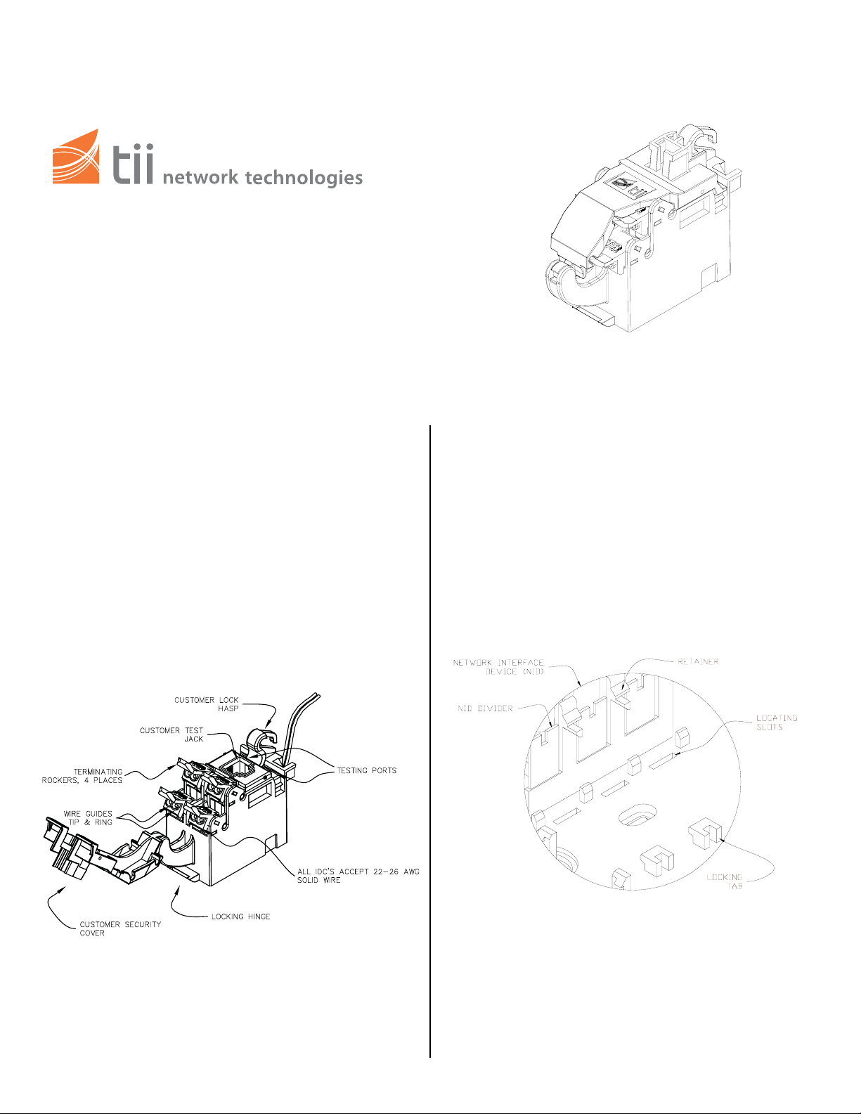
1. The TII 95S Series ADSL POTS Splitter
Module maintains a constant direct connection
between customer and central office service
provider. The Splitter Module is equipped with
a customer test jack (See Figure 1). The
customer can insert the RJ-11 plug from a
working telephone into this test jack to assure
a signal is received from the central office.
This is the only time the customer is
disengaged (both DSL and POTS service)
from the central office.
Features
Figure 1
Installation
1. Hold the Splitter Module with the cover pivot
side on right.
2. Lower the pivot side edge inside the
designated installation cavity.
3. Engage the right end ledge under the catch.
(See Figure 2).
4. Push the left side end down until the latch
snaps closed.
Figure 2
Page 2
Wiring
1. Three telephone voice (POTS) pairs and one
DSL line (DATA) can be connected to a single
Splitter Module. The customer has the option
of installing a #10 Master lock around the
customer lock hasp (See Figure 1).
2. When installing the first pair of customer
telephone wires, always begin with the bottom
terminating rockers (See Figure 1).
3. Do not strip wire insulation from wires to be
terminated to Splitter Module.
CAUTION: TO REDUCE THE RISK OF
!
PERSONAL INJURY, INSERT A RJ-11 PLUG
INTO THE CUSTOMER TEST JACK PRIOR TO
MAKING ANY WIRING CONNECTIONS.
4. Dress terminating wires (to protector) over NID
divider.
5. Insert and terminate TIP (GRN) & RING (RED)
wires into sealed IDC station protector (see
protector installation note for further details).
6. Open customer security cover on Splitter
Module.
7. Lift all Splitter Module rockers to the open
position as shown (See Figure 1).
8. Dress wires around custom er security cover.
9. Start wiring from the bottom left rocker.
10. Hold the customer voice telephone wires
between thumb and index finger (approx. 1/8”
separation between wires).
NOTE:
should be aligned to the corresponding holes. Green
wire to the “T” (GRN) labeled wire guide and the Red
wire to the “R” (RED) labeled wire guide.
IDC’s accept 22-26 AWG solid wire. Wires
11. Insert wires into wire guides at the same time
until they bottom out.
12. While holding wires in wire guides, terminate
rocker with thumb (lower rocker all the way).
13. Terminate additional voice pairs to lower right
and upper left rockers as required.
14. Terminate the DSL customer wire pair at
upper right locker only.
15. Assure all rockers are in the down position
and close customer security cover.
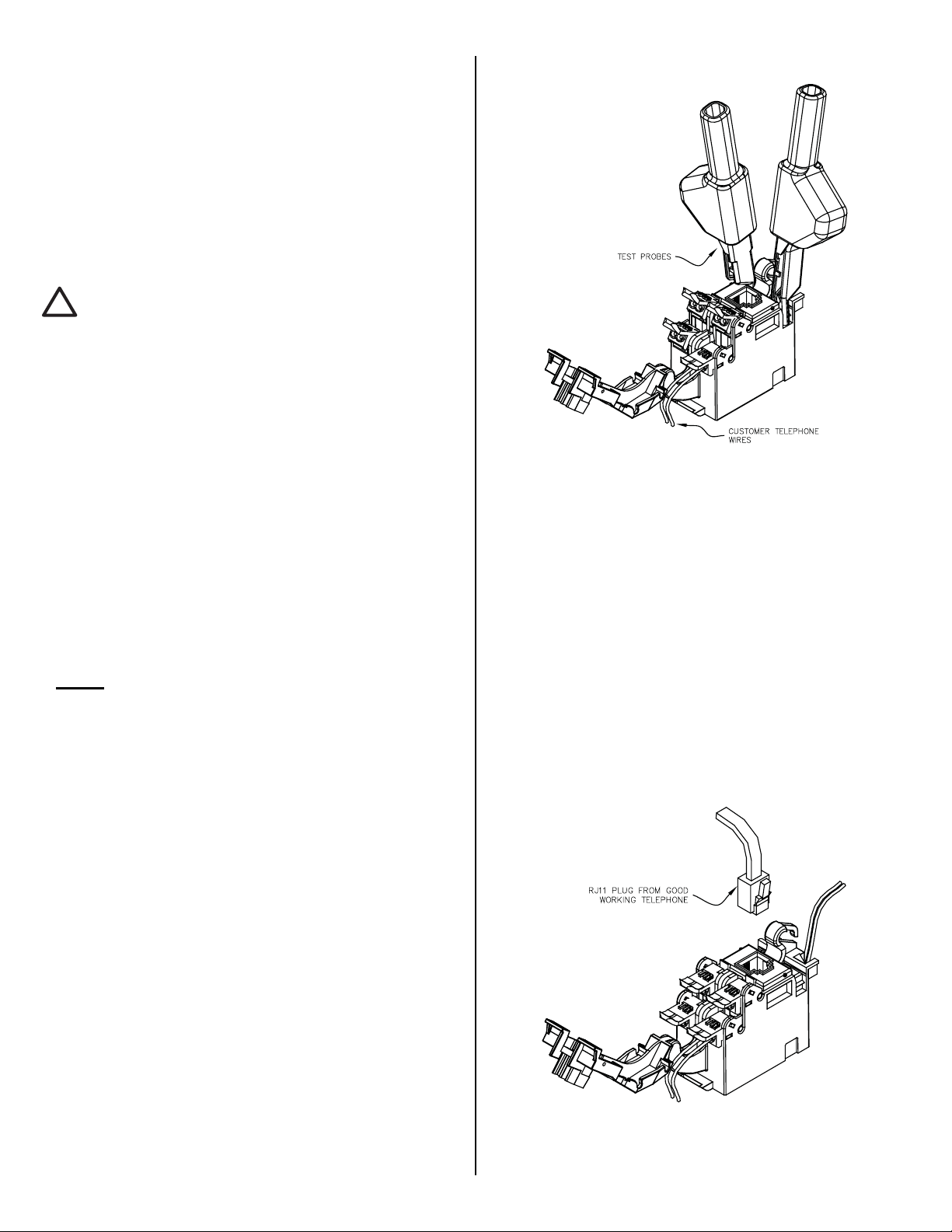
Central Office Signal Testing
1. Open customer security cover.
2. Insert RJ-11 plug into customer test jack to
isolate telco and customer wiring.
3. Using an ohmmeter, insert test clips into test
ports as shown (See Figure 3).
4. If continuity is measured, a “short” may exist in
the customer premise.
5. Wires are ok if meter shows a reading.
Figure 3
Customer Telephone Wire Integrity
Testing
1. Open customer security cover.
2. Using a working telephone, insert the
telephone RJ-11 plug into the customer test
jack (See Figure 4).
3. Wait a few seconds, lift receiver, and listen for
tone.
4. If dial tone is not present, then contact central
office service provider.
5. If dial tone is present, then a problem exists in
the customer telephone wires.
Figure 4
 Loading...