

Page 1
P/N 92208101 • Rev D• 4/30/2008
Warranty: If this unit fails during the warranty period, contact tii customer service to authorize return. Unit may be returned prepaid.
Model 95-1-00-1
Customer Bridge Module
With Autojack
Installation Note
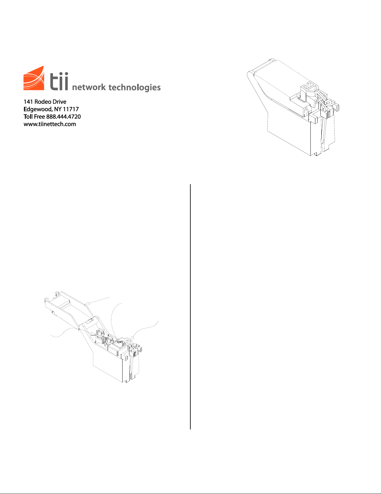
Customer Security Cover
Customer Test Jack
Customer Lock
Hasp
Customer Premise
Connections
*RJ11 Plug is not required for normal operation
Description
1. A Customer Bridge Module (CBM) maintains a
constant direct connection between customer
and central office service provider. The CBM
is equipped with a customer test jack.
Customer can insert the RJ-11 plug from a
working telephone into this test jack to assure
a signal is received from the central office.
This is the only time the customer is
disengaged from the central office.
Installation
Basic Operation
1. Inserting an R-J11 plug automatically
disconnects customer equipment and
connects to the central office. This operation
is usually performed during testing of the
telephone line.
2. By removing the RJ-11 plug, the customer is
automatically connected to the central office.
This is the normal operating mode
Installing CBM
1. Insert hinge side of module under tab on NID
enclosure. Dress wires to telco compartment.
Pull back NID retainer tab, push down module
until it snaps in place. Release retainer tab to
hold module firmly in place.
Wiring
1. A maximum of 4 telephone wires can be
attached to each wiring bridge screw. Insert
wire through grommet. Strip insulation from
wire. Pass wires behind hinge pin. Connect
wire to color corresponding terminals. (NOTE:
If customer wiring colors do not match Green
and Red, inspect the first jack in premise.
Determine which wire colors connect to Green
and Red in jack.)
2. Connect same wire colors to Green and Red
terminal screws in this housing. (Example:
White/Blue stripe to Green; Blue/White stripe
to Red). Wrap each clockwise between a
washer on screw.
Page 2

3. Insure excess wire ends are wrapped tightly
around screw. Tighten screws snugly. Tuck
excess wire in trough. Additional wires should
be coiled and stored in trough. Perform
customary tests. Close and snap cover
securely. (NOTE: Use a Master® Lock #10 or
equivalent (sold in local stores) when it is
desirable to lock individual covers.)
Testing
CAUTION: INSERT A PLUG INTO TEST
JACK PRIOR TO ANY WIRING CHANGES.
1. Plug a working phone directly into the test
jack. WAIT ONE MINUTE. Lift receiver. If
problem goes away, fault is in customer wiring
or equipment. If not, call telephone company.
Disconnect plug from jack, close cover.
 Loading...