

Page 1
P/N 92215701 • Rev C• 4/1/2008
Warranty: If this unit fails during the warranty period, contact tii customer service to authorize return. Unit may be returned prepaid.
Model tii 91 Series
Expansion Modules
Installation Note
Description
NOTE: RJ-11 PLUG IS
NOT REQUIRED FOR
NORMAL OPERATION.
Installation
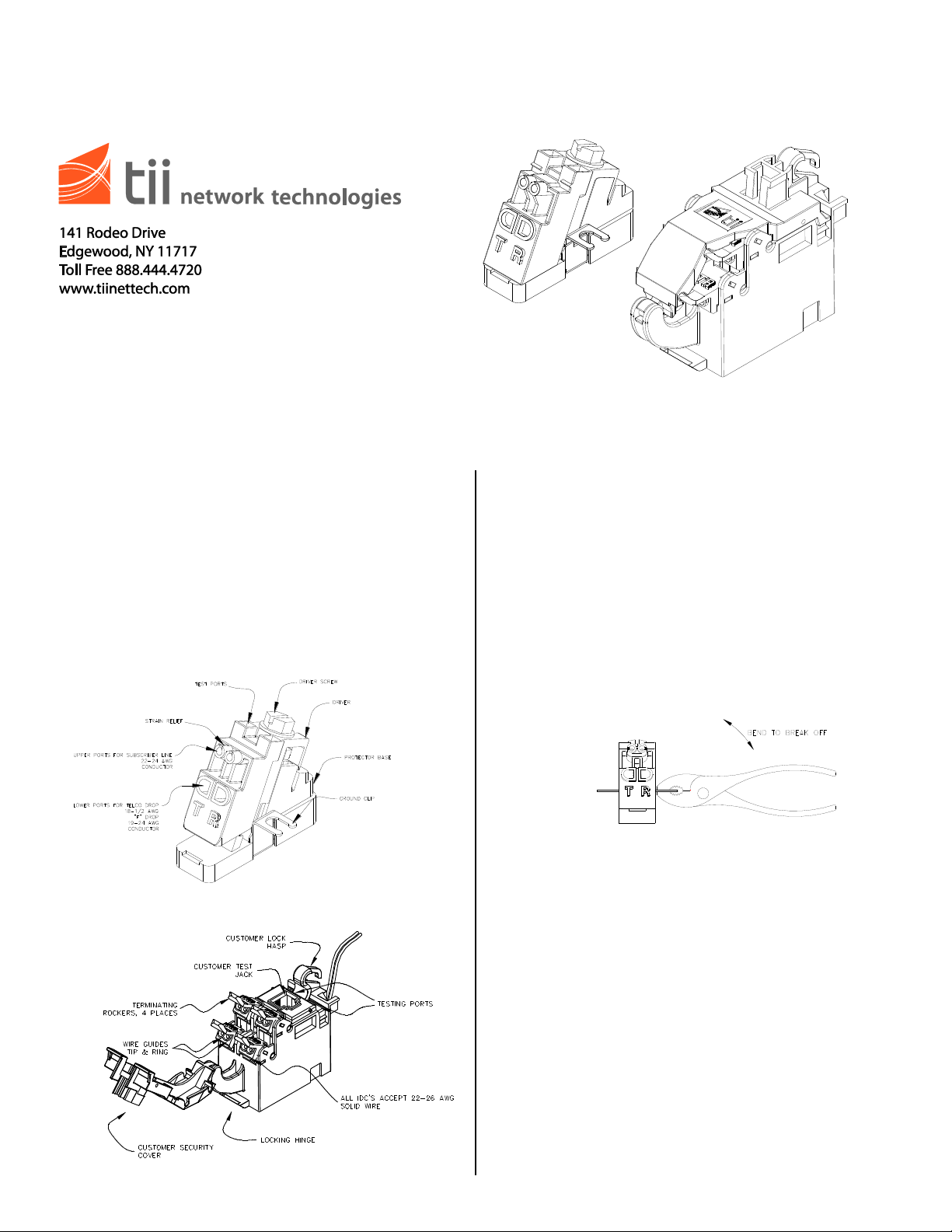
1. The tii 91 Series Expansion Modules consist
of a single station protector and a customer
bridge module required to upgrade or expand
subscriber lines within a tii Network Interface
Device (NID). They are available with either
traditional binding post terminations or gelsealed IDC terminations.
Features
Installing the Protector
1. The Angle Driver (Sealed IDC Protector) is
delivered with a universal grounding and
mounting tab (See Figure 1). If installing a
new module into a NID, break away the
unwanted ground tab from the module using a
pair of pliers and discard (See Figure 3).
Binding post protectors do not require this
step. Simply Install the module on desired
NID ground post and secure with washer and
nut.
Figure 1
Figure 2
Wiring
Angle Driver Sealed IDC Protector
1. The two upper ports of the Angle Driver are
intended to terminate subscriber (customer)
wires. Telco drop (feeder) wires must be
terminated in the two lower ports of the Angle
Driver.
2. Upper Port Subscriber Connections
(See Figure 4)
Subscriber terminations are already made in
the factory. If it is necessary to re-terminate a
subscriber wire, do so as follows:
2a. Do not strip wire insulation. Make certain
wire ends are cut flush with insulation.
Figure 3
Page 2
2b. Unscrew Angle Driver screw to the full
upright position.
2c. Fully insert the two subscriber wires into
their respective tip and ring (color-coded)
ports.
2d. Dress the wires through the strain relief
slots to hold them in place (See Figure 4).
Figure 4
3. Lower Port Telco Connections
(See Figure 5)
3a. Do not strip wire insulation. Make certain
wire ends are cut flush with insulation.
3b. Unscrew Angle Driver screw to full upright
position.
3c. Fully insert the two feeder (telco) wires into
their respective tip and ring (color-coded)
ports.
3d. While holding the two telco wires in place
tighten Drive Screw to full down position.
Figure 5
4. Binding Post Protector Wiring
4a. Strip the insulation from service drop wire
Tip (Green) approx. ½ inch. Loosen the lower
nut of one of the binding posts and wrap the
exposed conductor around the stud. Wire
should be between the two washers of the
lower nut. Tighten the nut to secure the
connection and repeat for the Ring (Red) wire.
4b. Wiring to the customer bridge modules
(from protector) is accomplished in the same
manner with the exception that the
connections are made between the two
washers of the upper nut for the station
protector.
Installation
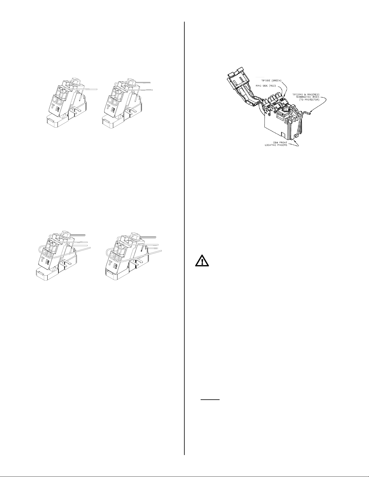
Installing the Customer Bridge Module
1. Hold the CBM module with the locking hinge
facing you. (See Figure 2)
2. Insert the CBM module locking hinge into the
Network Interface Device (NID) locking tab
(See Figure 7).
3. Pull back NID retainer (See Figure 7) and slip
CBM front locating fingers (See Figure 6) into
NID locating slot.
Figure 6
Wiring
CBM Wiring (Sealed IDC Connections)
1. Four independent telephone pairs can be
connected to a single CBM module. Customer
has the option of installing a #10 Master lock
in the customer lock hasp (See Figure 2).
2. When terminating the first pair to an IDC
connection, always begin with the bottom
terminating rockers (See Figure 2).
3. When terminating to an IDC connection, do
not strip wire insulation from wires.
CAUTION: TO REDUCE THE RISK OF
PERSONAL INJURY, INSERT A RJ-11 PLUG
INTO THE CUSTOMER TEST JACK PRIOR TO
MAKING ANY WIRING CONNECTIONS.
4. Dress terminating wires (to protector) over NID
divider (See Figure 7).
5. Insert and terminate TIP (GRN) & RING (RED)
wires into sealed IDC station protector (See
protector installation note for further details).
6. Open customer security cover on CBM
module.
7. Lift all CBM rockers to the open position as
shown (See Figure 2).
8. Dress wires around customer security cover.
9. Hold the customer telephone wires between
thumb and index finger (approx. 1/8”
separation between wires).
NOTE: Wires should be aligned to the corresponding
holes. Green wire to the “T” (GRN) labeled wire guide
and the Red wire to the “R” (RED) labeled wire guide.
10. Insert wires into wire guides at the same time
until they bottom out.
11. While holding wires in wire guides, terminate
rocker with thumb (lower rocker all the way).
Page 3

12. Terminate additional pairs to rockers as
required.
13. Assure all rockers are in the down position
and close customer security cover.
CBM Wiring (Screw Terminal Connections)
1. For binding post terminations, strip customer
wire ½ inch and terminate to the
corresponding Tip (green) and Ring (red)
screw terminals.
Screw Terminal Connections
1. Open customer security cover.
2. Insert RJ-11 plug into customer test jack to
isolate telco and customer wiring.
3. Using an ohmmeter, check for continuity
between the conductive heads of the tip
(green) and ring (red) screws.
4. If continuity is measured, a “short” may exist in
the customer premise.
5. Wires are ok if meter shows a reading.
6. Close customer security cover and inform
customer.
Figure 7
Central Office Signal Testing
Sealed CBM
1. Open customer security cover.
2. Insert RJ-11 plug into customer test jack to
isolate telco and customer wiring.
3. Using an ohmmeter, insert test clips into test
ports as shown (See Figure 8).
4. If continuity is measured, a “short” may exist in
the customer premise.
5. Wires are ok if meter shows a reading.
Customer Telephone Wire Integrity
Testing
1. Open customer security cover.
2. Using a working telephone, insert the
telephone RJ-11 plug into the customer test
jack (See Figure 9).
3. Wait a few seconds, lift receiver, and listen for
tone.
4. If dial tone is not present, then contact central
office service provider.
5. If dial tone is present, then a problem exists in
the customer telephone wires.
Figure 9
Figure 8
 Loading...