

Page 1
P/N 92211001 • Rev B• 5/7/2008
Warranty: If this unit fails during the warranty period, contact tii customer service to authorize return. Unit may be returned prepaid.
Model 90-3
SEALED BRIDGING MODULE
Installation Note
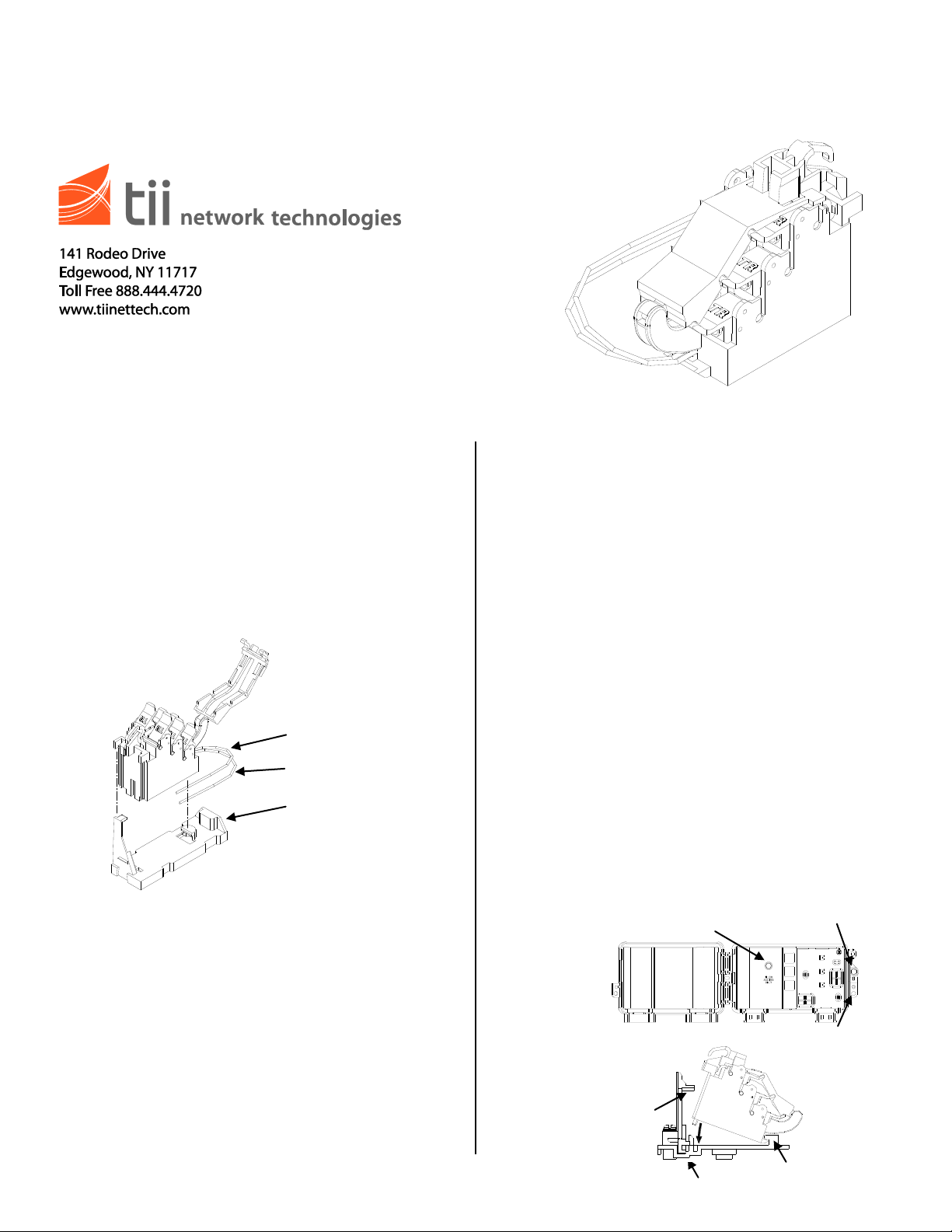
Adapter
(CAC 7600 Only)
Green (Tip)
Red (Ring)
Figure 1
Telco Shield Screw
Telco Access Screw
Subscriber Access Screw
Locking
Bar Tab
TII NID Base
Retaining Tab
Description
1. The TII 90-3 Sealed Bridging Module provides
sealed IDC terminations for connecting six
additional extensions to an existing phone line.
The module can be installed directly into all TII
Network Interface Devices and can be
adapted to fit into a CAC 7600 footprint using
an optional adapter.
Installation
Installing The 90-3 Into A TII
3600/3700/9600/5300 NID
1. Locate the Network Interface Device
2. Unlock the subscriber access cover screw
using a standard screwdriver (Figure 2).
3. Identify the appropriate line position to add the
bridging module.
4. Snap the bridging module to the base as
shown in Figure 3. For installation into a TII
3600/3700/9600/5300 NID, the adapter is not
required.
5. Terminate wire leads (Tip/Ring) from the
bridging module to terminals on the existing
Customer Bridge Module.
6. Do not strip wire insulation from wires to be
terminated to CBM.
7. Lift all CBM rockers to the open position as
shown (see Figure 1).
8. Hold the customer telephone wires between
thumb and index finger (approx. 1/8”
separation between wires).
Figure 2
Figure 3
Page 2
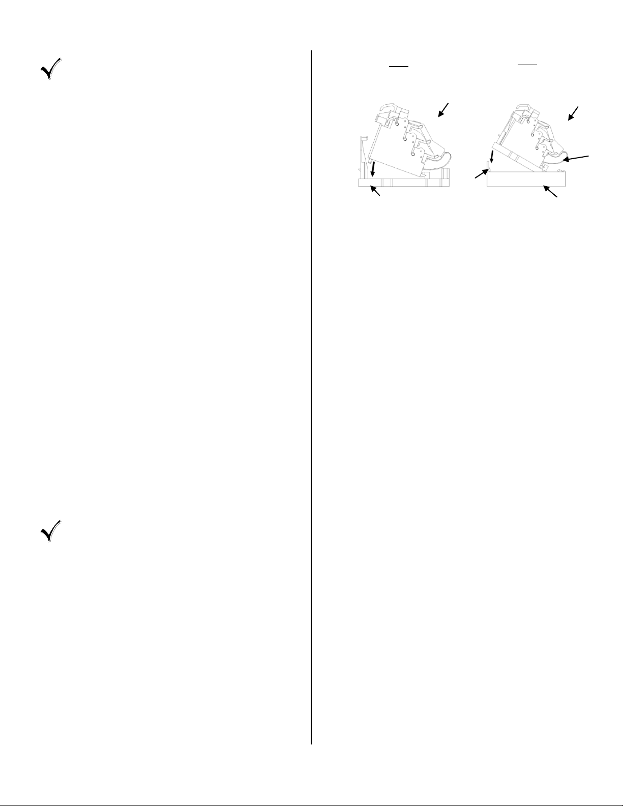
STEP 1
Load Bridging Module
Into Adapter
STEP 2
Load Module/Adapter
Assembly Into Base
Of Unit
Adapter
Bridging Module
Adapter
Locking
Bar Tab
CAC 7600 Base
Bridging Module
Figure 4
NOTE: Wires should be aligned to the
corresponding holes. Green wire to the
“T” (GRN) labeled wire guide and the
Red wire to the “R” (RED) labeled wire
guide.
9. Insert wires into wire guides at the same time
until they bottom out.
10. While holding wires in wire guides, terminate
rocker with thumb (lower rocker all the way).
11. Terminate additional pairs to rockers as
required.
12. Assure all rockers are in the down position
and close customer security cover.
13. Test for unit operation.
14. After wiring is complete, close and secure NID
cover (Figure 2).
Installing The 90-3 Sealed Bridging Module
Into A CAC 7600 Network Interface
1. Locate the Network Interface Device.
2. Unlock the cover (similar to Figure 2).
3. Identify the appropriate line position in the
NID.
4. Snap the bridging module into the adapter,
then into the base as shown in Figure 4.
5. Terminate wire leads (Tip/Ring) from the
bridging module to terminals on the existing
Customer Bridge Module.
6. Lift all CBM rockers to the open position as
shown (see Figure 1).
7. Hold the customer telephone wires between
thumb and index finger (approx. 1/8”
separation between wires).
NOTE: Wires should be aligned to the
corresponding holes. Green wire to the
“T” (GRN) labeled wire guide and the
Red wire to the “R” (RED) labeled wire
guide.
8. Insert wires into wire guides at the same time
until they bottom out.
9. While holding wires in wire guides, terminate
rocker with thumb (lower rocker all the way).
10. Terminate additional pairs to rockers as
required.
11. Assure all rockers are in the down position
and close customer security cover.
12. Test for unit operation.
13. After wiring is complete, close and secure NID
cover (Figure 2).
 Loading...