

Page 1
▲WARNING: Do not install this unit or work
with telephone wiring during a lightning
storm. Telephone lines can carry high voltages from lightning, which can cause electric
shock resulting in severe injury or death.
CAUTION: Avoid the possibility of electric
shock from ringing voltage, when installing
this unit or working with telephone wiring.
Temporarily disconnect the subscriber wiring,
by inserting an RJ-11 plug in the jack at the
location you will be wiring. Never touch uninsulated wiring or terminals unless the line
has been disconnected.
141 Rodeo Drive Tii 8925 Series
Edgewood, NY 11717 Indoor Network Interface
Toll Free 888.844.4720 P/N 92211501
www.tiinettech.com 01/08 Rev B
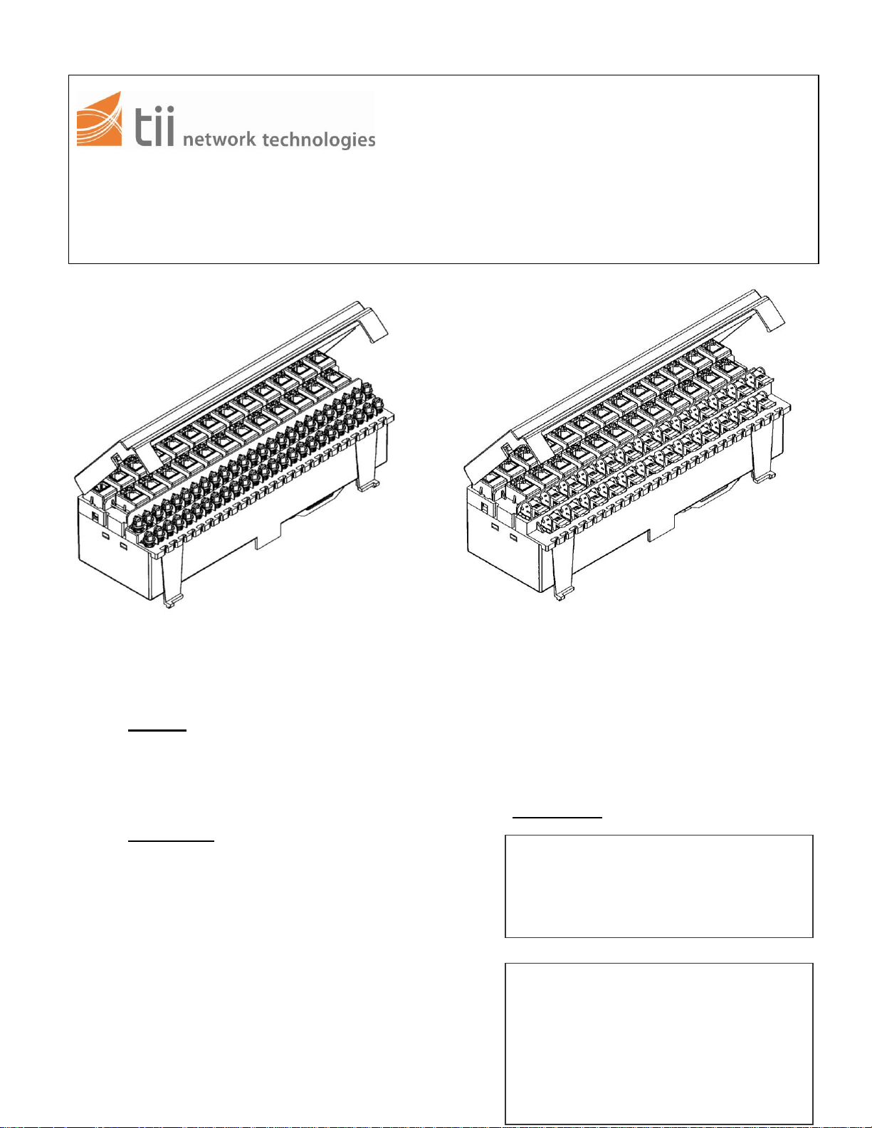
FIGURE 1
(SCREW TERMINAL VERSION)
8925B SERIES
1. General
1.1 This installation note describes the in-
stallation of the tii 8925 Series (25-line) Indoor
Network Interface (INI) manufactured by tii.
2. Description
2.1 The 8925 Series INI is a demarcation
device that separates subscriber-owned from
telco-owned wiring. The demarcation is provided by a RJ-11 test jack for each of the 25
lines inside the unit. The compact design of the
8925 Series INI allows for easy installation in
areas with limited space.
2.2 The unit is designed for use in place of
a 66 block. Using the same footprint as the 66
block, the 8925 Series INI is easily installed to
an 89B or 89D bracket (Figure 3).
INSTALLATION NOTE
2.3 Telco connection is accomplished by
means of a 25-pair connector (RJ-21) on the
rear of the unit (Figure 4).
FIGURE 2
(INSULATION DISPLACEMENT CLIP VERSION)
8925A SERIES
2.4 The subscriber interface panel includes
a hinged cover with wiring/testing instructions.
3. Precautions
Page 2
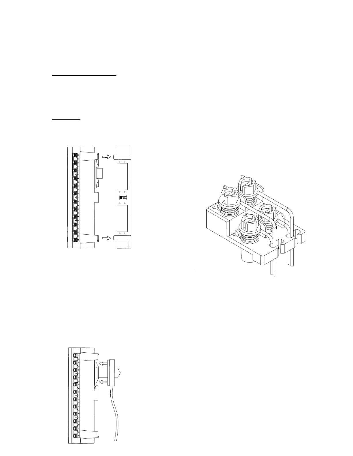
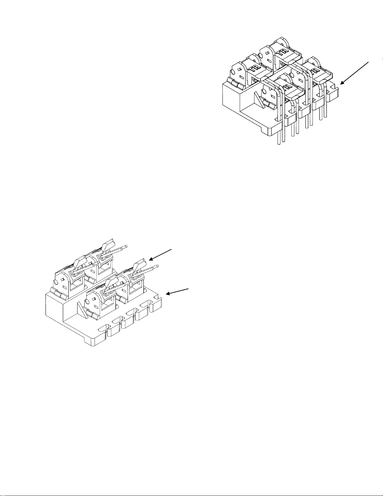
FIGURE 7
4. Tools and Equipment
The normal complement of mechanical
tools is recommended for mounting and wiring
the unit.
5. Mounting
Using an 89B bracket, simply snap the
8925 Series INI on to the bracket (Figure 3).
FIGURE 3
6. Telco Wiring
6.1 The 8925 Series INI is provided with an
RJ-21 connector on the rear of the unit. Telco
connection is made by means of a 25-pair
wired standard male connector that is secured
to the back of the unit with the provided hookand-loop strap (Figure 4).
FIGURE 4
7. Subscriber Wiring – Screw Terminal
Version – 8925B Series (Figure 1)
7.1 Open the orange cover and temporarily
disconnect the subscriber wiring by inserting an
RJ-11 plug in the jack at the location you will be
wiring.
7.2 Route subscriber wires through the wire
rungs attached to the subscriber bridge you will
be using. Strip off about ½ inch of insulation
from each wire (see Figure 7).
7.3 Loosen the terminal screws about one
turn and wrap the stripped wires under them –
between the washers. Match wires, color-tocolor (example: red wire to terminal post
marked red, or a letter “R, green wire to a ter-
minal post marked green or “G” and so on).
Retighten the terminal screws (see Figure 7).
7.4 Remove the temporary inserted RJ-11
plug from the modular plug.
7.5 Use approved practices to test the line.
8. Subscriber Wiring – IDC Terminals
(Figure 2)
Open the orange cover and temporarily disconnect the subscriber wiring by inserting RJ-
Page 3
IDC ROCKER IN
UP POSITION
WIRE RUNGS
IDC ROCKER IN
DOWN/TERMINATED
POSITION
FIGURE 6
11 plug in the jack at the location you will be
wiring.
8.2 Wiring the IDC terminals:
a) place IDC rockers in up position
(Figure 5);
b) match wires, color-to-color (example:
red wire (ring) to red rocker; green wire (tip) to
green rocker);
c) fully insert wire into the proper hole of
the IDC rocker;
d) close rocker to full down position to terminate pair (Figure 6).
8.3 Route subscriber wires through the wire
rungs attached to the subscriber bridge you will
be using (Figure 6).
8.4 Use approved practices to test the line.
FIGURE 5
 Loading...