

Tii 87 User Manual
g
tii 87
141 Rodeo Drive Sealed Subscriber Bridge with POTS Suppression
Edgewood, NY 11717 TII P/N: 92213601
Customer Service/Sales 888-844-4720 Rev C 6/09
INSTALLATION NOTE
BASIC OPERATION
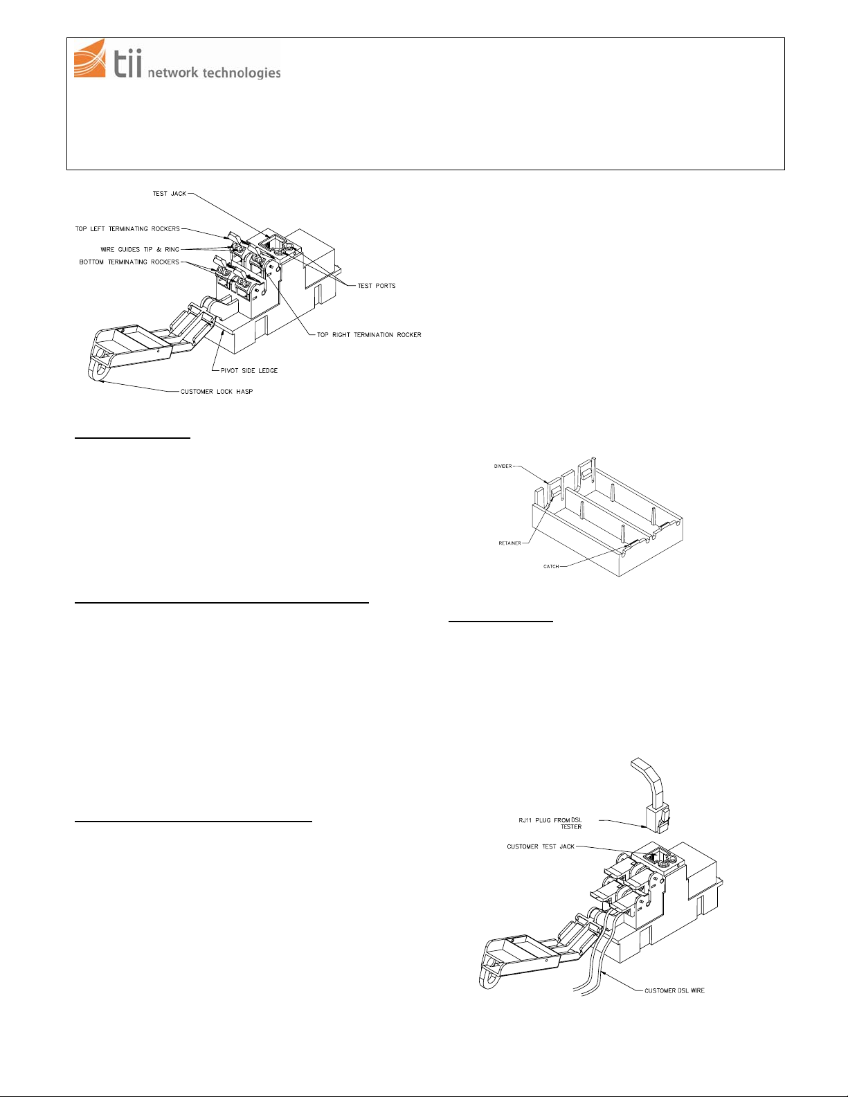
Figure 1
The TII 87 series Sealed Subscriber Bridge with POTS
Suppression (Bridge) allows high speed DSL transmission
between customer and central office while suppressing
POTS. The Bridge is equipped with a test jack and IDC
terminations (see Figure 1). The RJ-11 plug of test
equipment can be inserted into the test jack to assure a
DSL signal is received from the office. This is the only
time the customer is disengaged from the central office.
INSTALLING THE SEALED SUBSCRIBER BRIDGE
• Remove the Bridge from plastic bag and inspect; if
damaged, replace with an undamaged Bridge.
• Hold the Bridge with the cover pivot side on right.
• Lower the pivot side edge inside the designated
installation cavity.
• Engage the right end ledge under the catch. (See
Figure 2)
• Push the left side end down until the latch snaps
closed.
SEALED SUBSCRIBER BRIDGE WIRING
• The Bridge has a pair of wires that are to be
connected to the protector module. The customer has
the option of installing a #10 Master lock around the
customer lock hasp (see Figure 1).
• Do not strip wire insulation from wires to be
terminated to protector.
• Dress terminating wires (to protector) over NID
divider.
• Insert and terminate wires into sealed IDC station
protector (see protector installation note for further
details).
• Open customer security cover on Bridge.
• Lift one Bridge rocker to the open position as shown
(see Figure 1).
• Dress wires around customer security cover.
• Hold the customer DSL pair wires between thumb and
index finger (approx. 1/8” separation between wires).
NOTE: Only use one of the rockers. All rockers are
bridged together.
• Insert wires into wire guides at the same time until
they bottom out.
• While holding wires in wire guides, terminate rocker
with thumb (lower rocker all the way).
• Assure the rocker is in the down position and close
customer security cover.
Figure 2
SIGNAL TESTING
• Open customer security cover.
• Using a portable data test set, insert RJ-11 test plug
into customer test jack (see Figure 3).
• Verify that the portable DSL test set is able to
communicate with central office.
• POTS will not be detected at the test jack.
Fi
ure 3
 Loading...